D-Link DGS-1248T Product Manual
D-Link DGS-1248T - Switch Manual
 |
UPC - 790069272479
View all D-Link DGS-1248T manuals
Add to My Manuals
Save this manual to your list of manuals |
D-Link DGS-1248T manual content summary:
- D-Link DGS-1248T | Product Manual - Page 1
- D-Link DGS-1248T | Product Manual - Page 2
Switch...4 Login Web-based Management Utility ...5 Smart Wizard ...5 Web-based Management Utility...5 SmartConsole Utility...5 Product Introduction ...7 DGS-1216T ...7 Front Panel ...7 Rear Panel...8 DGS-1224T ...8 Front Panel ...8 Rear Panel...9 DGS-1224TP...9 Front Panel ...9 Rear Panel...10 DGS - D-Link DGS-1248T | Product Manual - Page 3
Table of Contents D-Link Web Smart Switch User Manual SNMP Settings ...20 System Settings...21 Identifying the Web-based Management Utility 22 Tool Menu ...22 Reset ...22 Configure Backup & Restore...23 Firmware Backup and Upload ...23 System Reboot ...24 Setup Menu...24 System > System Settings - D-Link DGS-1248T | Product Manual - Page 4
Table of Contents D-Link Web Smart Switch User Manual QoS (Quality of Service)...3 Security...3 Management...3 iii - D-Link DGS-1248T | Product Manual - Page 5
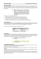
About This Guide D-Link Web Smart Switch User Manual About This Guide This guide provides instructions to install D-Link Gigabit Ethernet Web Smart Switches DGS1216T/24T/24TP/48T, how to use the SmartConsole Utility, and to configure Web-based Management Utility step-by-step. Note: The model you - D-Link DGS-1248T | Product Manual - Page 6
the User Manual to make sure all items are present and undamaged. If any item is missing or damaged, please contact your local D-Link reseller for replacement. One D-Link Web-Smart Switch One AC power cord Four rubber feet Screws and two mounting brackets One Multi-lingual Getting Started Guide User - D-Link DGS-1248T | Product Manual - Page 7
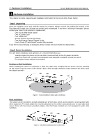
Installation D-Link Web Smart Switch User Manual Then, use the screws provided with the equipment rack to mount the switch in the rack. Figure 3 - Mount the Switch in the rack or chassis Step 3 - Plugging in the AC Power Cord Users may now connect the AC power cord into the rear of the switch and - D-Link DGS-1248T | Product Manual - Page 8
Started D-Link Web Smart Switch User Manual 2 Getting Started This chapter guides you how to get into and introduces the management interface of D-Link Web-Smart Switch. Management Options The D-Link Web Smart Switch can be managed through any port on the device by using the Web-based Management - D-Link DGS-1248T | Product Manual - Page 9
Link Web Smart Switch User Manual Login Web-based Management Utility In order to login and configure the switch via an Ethernet connection, the PC must have an IP address in the same subnet as the switch. For example, if the switch has an IP address of 192.168.0.1, the PC should have an IP address - D-Link DGS-1248T | Product Manual - Page 10
2 Getting Started D-Link Web Smart Switch User Manual Option 1: Follow these steps to install the on-screen instructions to install the utility. 5. Upon completion, go to Start > Programs > D-Link SmartConsole Utility and open the SmartConsole Utility. 6. Just connect the Smart Switch to the same - D-Link DGS-1248T | Product Manual - Page 11
events. MIB support allows users to integrate the switches with third-party devices for management in an SNMP environment. DGS-1216T 16 Port 10/100/1000BaseT with 2 Combo SFP Smart Switch Front Panel Figure 8 - DGS-1216T Front Panel Power LED: The Power LED flashes when the Switch is connected to - D-Link DGS-1248T | Product Manual - Page 12
pressing the Reset button the Switch will change back to the default configuration and all changes will be lost. Power: The power port is where to connect the AC power cord. DGS-1224T 24 Port 10/100/1000BaseT with 2 Combo SFP Smart Switch Front Panel Figure 10 - DGS-1224T Front Panel Power LED: The - D-Link DGS-1248T | Product Manual - Page 13
Panel D-Link Web Smart Switch User Manual Figure 11 - DGS-1224T Rear Panel Reset: By pressing the Reset button the Switch will change back to the default configuration and all changes will be lost. Power: The power port is where to connect the AC power cord. DGS-1224TP 24 Port 10/100/1000BaseT - D-Link DGS-1248T | Product Manual - Page 14
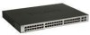
By pressing the Reset button the Switch will change back to the default configuration and all changes will be lost. Rear Panel Figure 13 - DGS-1224TP Rear Panel Power: The power port is where to connect the AC power cord. DGS-1248T 48 Port 10/100/1000BaseT with 4 Combo SFP Smart Switch Front Panel - D-Link DGS-1248T | Product Manual - Page 15
3 Product Introduction Rear Panel D-Link Web Smart Switch User Manual Figure 15 - DGS-1248T Rear Panel Power: The power port is where to connect the AC power cord. 11 - D-Link DGS-1248T | Product Manual - Page 16
D-Link Web Smart Switch User Manual 4 SmartConsole Utility D-Link SmartConsole Utility allows the administrator to quickly discover all D-Link smart switches which are in the same domain the PC, collect traps and log messages, and quick access to some basic configurations of the switch. The - D-Link DGS-1248T | Product Manual - Page 17
Link Web Smart Switch User Manual Log By clicking on this icon the Log window will pop up. Click View Log to show the events of the SmartConsole Utility and the device. Date/Time indicates when the log was received, IP indicates when the trap was received, IP indicates where it comes from and Status - D-Link DGS-1248T | Product Manual - Page 18
4 SmartConsole Utility D-Link Web Smart Switch User Manual Figure 20 - SmartConsole File Monitor Save: To record the setting of the Device List as default for the next time the SmartConsole Utility is used. Monitor Save As: To record the setting of the Device List in an appointed filename and - D-Link DGS-1248T | Product Manual - Page 19
D-Link Web Smart Switch User Manual Device Configurations The Device Configurations in the SmartConsole Utility has five icons: Device Settings Device Password Manager Firmware Upgrade DHCP Refresh Web Access and the , , device buttons for the Device List. Device Settings Select a switch - D-Link DGS-1248T | Product Manual - Page 20
D-Link Web Smart Switch User Manual Device Password Manager Select a switch from the Device List, then clicking on this icon the Device Password Manager window will pop up. Here you can enter a new password and confirm. Figure 23 - SmartConsole Device Password Manager Firmware Upgrade Select - D-Link DGS-1248T | Product Manual - Page 21
Utility D-Link Web Smart Switch User Manual Web Access Select a switch from the Device List, then clicking this icon an internet browser will pop up (default is Internet Explorer). Here you can configure the Switch through the Web-based Management Utility. You may also get into the Web-based - D-Link DGS-1248T | Product Manual - Page 22
4 SmartConsole Utility D-Link Web Smart Switch User Manual Device List This is the list where all Web-Smart devices on the network are discovered. Figure 28 - SmartConsole Device List Definitions of the Device List features: Monitor: Check the Monitor box, and the SmartConsole - D-Link DGS-1248T | Product Manual - Page 23
D-Link Web Smart Switch User Manual 5 Configuration Through a Web-based Management Utility, the features and functions of the D-Link Web Smarty Switch can be configured for optimum use. Smart Wizard Configuration Before entering the Web-based Management Utility, When The Smart Wizard will guide - D-Link DGS-1248T | Product Manual - Page 24
5 Configuration D-Link Web Smart Switch User Manual SNMP Settings The SNMP Setting allows you to quick enable/ disable the SNMP function and configure the SNMP community name. For detail SNMP function description please see "Setup Menu > System > SNMP Settings". The default SNMP Setting is - D-Link DGS-1248T | Product Manual - Page 25
D-Link Web Smart Switch User Manual System Settings By selecting Static and clicking Apply you can manually change the system IP Address, Subnet Mask, and Gateway address. You can further configure and read more about the above settings in the "Setup Menu > System > System Settings". The default - D-Link DGS-1248T | Product Manual - Page 26
. For learn the further information to configuring the D-Link Web Smart Switch via Web-based Management Utility, please check the "Configuration" section. Tool Menu The Tool Menu offers global function controls such as Reset, Configuring Backup and Restoration, Firmware Backup and Upload, and System - D-Link DGS-1248T | Product Manual - Page 27
5 Configuration D-Link Web Smart Switch User Manual Configure Backup & Restore Allow the current configuration settings to be saved to a file (not including the password), and if necessary, to be restored from a backup. Figure 36 - Tool Menu > Configure Backup and Restore Click Backup to save the - D-Link DGS-1248T | Product Manual - Page 28
5 Configuration D-Link Web Smart Switch User Manual System Reboot Provide a safe way to reboot the system. Click System Reboot to restart the switch. Figure 38 - Tool Menu > System Reboot Setup Menu All configuration options on the switch are accessed through the Setup menu on the left side of - D-Link DGS-1248T | Product Manual - Page 29
User Manual Figure 40 - System > System Setting System > Trap Settings By configuring the Trap Setting, it allows SmartConsole Utility to monitor specified events on this Web-Smart Switch. By default, Trap Setting is disabled. When the Trap Setting is enabled, enter the Destination IP address - D-Link DGS-1248T | Product Manual - Page 30
5 Configuration D-Link Web Smart Switch User Manual System > Port Settings In the Port Setting page, the status of all ports can be monitored and adjusted for optimum configuration. By selecting a range of ports (From Port and To Port), the Speed can be set for all such ports, by clicking Apply. - D-Link DGS-1248T | Product Manual - Page 31
5 Configuration D-Link Web Smart Switch User Manual Figure 43 - System > SNMP Setting Community Setting: In support of SNMP version 1, the Web-Smart Switch accomplishes user authentication by using Community Settings that function as passwords. The remote user SNMP application and the Switch SNMP - D-Link DGS-1248T | Product Manual - Page 32
effect. Figure 44 - System > Password Access Control Configuration > Jumbo Frame D-Link Gigabit Web Smart Switches support jumbo frames (frames larger than the Ethernet frame size of 1536 bytes) of up to 10240 bytes (tagged) can be transmitted by the Switch. Default is disabled, Select Enabled then - D-Link DGS-1248T | Product Manual - Page 33
5 Configuration D-Link Web Smart Switch User Manual Figure 47 - Configuration > 802.1Q VLAN > Add VID Figure 48 - Configuration > 802.1Q VLAN > Example VIDs Figure 49 - Configuration > 802.1Q VLAN > VID Assignments Configuration >Asymmetric VLAN This function is located in the 802.1Q Configuration - D-Link DGS-1248T | Product Manual - Page 34
5 Configuration D-Link Web Smart Switch User Manual PC 1 (Port 5) PC 2 (Port 6) PC 3 (Port 7) Firewall Servers Figure 50 - Configuration > 802.1Q VLAN > Asymmetric VLAN Example 1. Enable Asymmetric VLAN Enable Asymmetric VLAN and click Apply button. The overlapping VLAN cannot be configured - D-Link DGS-1248T | Product Manual - Page 35
5 Configuration D-Link Web Smart Switch User Manual 3 and 4 groups are incapable of sharing information with each other. Click Example to see the example to configure asymmetric VLAN in larger networks. Configuration > 802.1Q Management VLAN 802.1Q Management VLAN setting allows you to transfer - D-Link DGS-1248T | Product Manual - Page 36
5 Configuration D-Link Web Smart Switch User Manual Figure 56 - Configuration > IGMP Snooping Configuration By default, IGMP is disabled. If enabled, the IGMP Global Settings will need to be entered: Querier State: D-Link Smart Switch is able to send out the IGMP Queries to check the status of - D-Link DGS-1248T | Product Manual - Page 37
5 Configuration D-Link Web Smart Switch User Manual Figure 57 - Configuration > IGMP Router port Settings To view the Multicast Entry Table for a given VLAN, press the View button. Figure 58 - Configuration > IGMP Multicast Entry Table Configuration > 802.1D Spanning Tree 802.1D Spanning Tree - D-Link DGS-1248T | Product Manual - Page 38
The default is 15 seconds. Root Bridge: Displays the MAC address of the Root Bridge. Root port: Displays the root port. Root Path Cost: Shows the root path cost. In addition to 802.1D global settings, the D-Link Web smart switch allows the user to configure 802.1D STP by ports. Select From Port / To - D-Link DGS-1248T | Product Manual - Page 39
costs. By default, the Power Saving mode is enabled. Figure 61 - Configuration > Power Saving Power over Ethernet (PoE) > PoE Port Settings (Only for DGS-1224TP) DGS-1224TP supports Power over Ethernet (PoE) as defined by the IEEE 802.3af specification. Ports 1-24 can supply 50VDC power to PDs - D-Link DGS-1248T | Product Manual - Page 40
5 Configuration D-Link Web Smart Switch User Manual Figure 62 - PoE > PoE Port Setting PoE Enable: Select to enable or disable the PoE function by ports. Power Limit: This function allows you to manually set the port power current limitation to be given to the PD. To protect the DGS-1224TP and the - D-Link DGS-1248T | Product Manual - Page 41
5 Configuration D-Link Web Smart Switch User Manual Note: When there is a system power shortage with the PD, the Switch will enforce the PoE port priority management. The lower port numbers will have priority over the higher port numbers. For example, Port 1 > Port 2 > ... > Port 24. QoS > 802.1p/ - D-Link DGS-1248T | Product Manual - Page 42
5 Configuration D-Link Web Smart Switch User Manual By selecting the DSCP priority, the web pages will changes as seen below: Figure 65 - QoS > DSCP Priority Settings Select QoS Mode: D-Link Smart Switch allows the user to prioritize the traffic based on the 802.1p priority in the VLAN tag or the - D-Link DGS-1248T | Product Manual - Page 43
5 Configuration D-Link Web Smart Switch User Manual mask setting, the format can be either 192.168.1.1/255.255.255.0 or 192.168.0.1/24. Please see below for the example for permitting the IP range IP Address IP Mask Permitted IP 192.168.0.1 255.255.255.0 192.168.0.1~192.168.0.255 172.17.5.215 - D-Link DGS-1248T | Product Manual - Page 44
5 Configuration D-Link Web Smart Switch User Manual Security > 802.1X Settings Network switches provide easy and open access to resources by simply attaching a client PC. Unfortunately this automatic configuration also allows unauthorized personnel to easily intrude and possibly gain access to - D-Link DGS-1248T | Product Manual - Page 45
5 Configuration D-Link Web Smart Switch User Manual Security > Mac Address Table > Static Mac This page provides two distinct features. The top table provides the ability to turn off auto learning Mac address if a port isn't connected to an uplink Switch (i.e. DHCP Server). By default, this - D-Link DGS-1248T | Product Manual - Page 46
5 Configuration D-Link Web Smart Switch User Manual Monitoring > Statistics The Statistics screen displays the status of each port packet count. Figure 72 - Monitoring > Statistics Refresh: To renew the details collected and displayed. Clear Counter: To reset the details displayed. TxOK: Number - D-Link DGS-1248T | Product Manual - Page 47
5 Configuration D-Link Web Smart Switch User Manual Figure 74 - Monitoring > Cable Diagnostic Test Result: The meters, 50~80 meters, 80~100 meters and >100 meters. NOTE: Cable length detection is supported on Gigabit ports only. NOTE: Please make sure the power saving function is disabled before - D-Link DGS-1248T | Product Manual - Page 48
A - Ethernet Technology D-Link Web Smart Switch User Manual Appendix A - Ethernet Technology This chapter provides some background information about Ethernet/Fast Ethernet/Gigabit Ethernet switching technology. Gigabit Ethernet Technology Gigabit Ethernet is an extension of IEEE 802.3 Ethernet - D-Link DGS-1248T | Product Manual - Page 49
Appendix A - Ethernet Technology D-Link Web Smart Switch User Manual Power and Data are integrated onto the same cable. Supporting category 5/5e up to 100 Meters, PoE will provide power to PoE compatible devices, such as IP telephones, wireless LAN access points, and IP security cameras. PoE is - D-Link DGS-1248T | Product Manual - Page 50
Specifications D-Link Web Smart Switch User Manual Appendix B - Technical Specifications Hardware Specifications Key Components / Performance Switching Capacity: - DGS-1216T: 32Gbps - DGS-1224T: 48Gbps - DGS-1224TP: 48Gbps - DGS-1248T: 96Gbps Max. Forwarding Rate - DGS-1216T: 23.8Mpps - DGS-1224T - D-Link DGS-1248T | Product Manual - Page 51
Appendix B - Technical Specifications Port access control Web-based configuration backup / restoration Web-based firmware backup/upload Firmware upgrade using SmartConsole Utility Reboot D-Link Web Smart Switch User Manual iv - D-Link DGS-1248T | Product Manual - Page 52
-
 1
1 -
 2
2 -
 3
3 -
 4
4 -
 5
5 -
 6
6 -
 7
7 -
8
-
9
-
10
-
11
-
12
-
13
-
14
-
15
-
16
-
17
-
18
-
19
-
20
-
21
-
22
-
23
-
24
-
25
-
26
-
27
-
28
-
29
-
30
-
31
-
32
-
33
-
34
-
35
-
36
-
37
-
38
-
39
-
40
-
41
-
42
-
43
-
44
-
45
-
46
-
47
-
48
-
49
-
50
-
51
-
52
 |
 |