D-Link DGS-3000-10TC Hardware Installation Guide
D-Link DGS-3000-10TC Manual
 |
View all D-Link DGS-3000-10TC manuals
Add to My Manuals
Save this manual to your list of manuals |
D-Link DGS-3000-10TC manual content summary:
- D-Link DGS-3000-10TC | Hardware Installation Guide - Page 1
- D-Link DGS-3000-10TC | Hardware Installation Guide - Page 2
D-Link Corporation is strictly forbidden. Trademarks used in this text: D-Link and the D-LINK logo are trademarks of D-Link Corporation frequency energy and, if not installed and used in accordance with this manual, may cause harmful interference to radio communications. Operation of this equipment - D-Link DGS-3000-10TC | Hardware Installation Guide - Page 3
DGS-3000 Series Layer 2 Managed Gigabit Switch Hardware Installation Guide Table of Contents Intended Readers ...v Typographical Conventions ...v Notes, Notices, and Cautions ...v Safety Instructions ...vi Safety Cautions ...vi General Precautions for Rack-Mountable Products ...vii Protecting - D-Link DGS-3000-10TC | Hardware Installation Guide - Page 4
DGS-3000 Series Layer 2 Managed Gigabit Switch Hardware Installation Guide Web Pages ...31 Appendix Section ...32 Appendix A - Technical Specifications...32 General ...32 Physical ...37 Console Cable ...38 Redundant Power Supply (RPS) Cable ...39 Warranties & Technical Support Information ...40 iv - D-Link DGS-3000-10TC | Hardware Installation Guide - Page 5
Discharge The DGS-3000 Series Hardware Installation Guide contains information for set up and management of the Switch. This manual is intended for network managers familiar with network management concepts and terminology. For all practical reasons the DGS-3000-10TC, and DGS-3000-26TC will - D-Link DGS-3000-10TC | Hardware Installation Guide - Page 6
DGS-3000 Series Layer 2 Managed Gigabit Switch Hardware Installation Guide Safety Instructions Use the following safety . If the system gets wet, see the appropriate section in the troubleshooting guide or contact your trained service provider. • Do not push any objects into the openings of the - D-Link DGS-3000-10TC | Hardware Installation Guide - Page 7
DGS-3000 Series Layer 2 Managed Gigabit Switch Hardware Installation Guide any system as well as to various peripherals or supporting hardware. CAUTION: Installing systems in a rack Do not step on or stand on any component when servicing other components in a rack. NOTE: A qualified electrician must - D-Link DGS-3000-10TC | Hardware Installation Guide - Page 8
DGS-3000 Series Layer 2 Managed Gigabit Switch Hardware Installation Guide CAUTION: The system chassis must be positively grounded to the rack cabinet frame. Do not attempt to connect power to the system until grounding cables - D-Link DGS-3000-10TC | Hardware Installation Guide - Page 9
: • DGS-3000-10TC: 8-Port 10/100/1000 BASE-T + 2-Port Combo 10/100/1000BASE-T/SFP, L2 Management Switch. • DGS-3000-26TC: 8-Port 10/100/1000 BASE-T + 2-Port Combo 10/100/1000BASE-T/SFP, L2 Management Switch. Features The list below highlights the significant protocols and features supported by the - D-Link DGS-3000-10TC | Hardware Installation Guide - Page 10
DGS-3000 Series Layer 2 Managed Gigabit Switch Hardware Installation Guide • Single IP • Port Mirroring • LLDP • NLB • Traffic segmentation • D-Link Safeguard Engine • Japanese Web-based Access Control (JWAC) • MAC server screening • ARP spoofing prevention • MIB support for: o RFC 1213 MIB II o RFC - D-Link DGS-3000-10TC | Hardware Installation Guide - Page 11
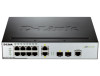
and manual. Front Panel Components The front panel of the Switch consists of LED indicators for Power, Console, RPS, Fan Err, and for Link/Act for each port on the Switch including SFP port LEDs. DGS-3000-26TC has an alarm port at the front panel. Figure 1-1 Front panel view of the DGS-3000-10TC 3 - D-Link DGS-3000-10TC | Hardware Installation Guide - Page 12
DGS-3000 Series Layer 2 Managed Gigabit Switch Hardware Installation Guide Figure 1-2 Front panel view of the DGS-3000-26TC 4 - D-Link DGS-3000-10TC | Hardware Installation Guide - Page 13
2 Managed Gigabit Switch Hardware Installation Guide LED Indicators The Switch front panel presents LED indicators for Power, Console, RPS, Fan Err, and Link/Act indicators for all ports including the Gigabit Ethernet ports. Figure 1-3 LED indicators for the DGS-3000-10TC LED Power Console RPS Fan - D-Link DGS-3000-10TC | Hardware Installation Guide - Page 14
supply or a DC power supply, and security lock. Figure 1-5 Rear panel view of the DGS-3000-10TC Figure 1-6 Rear panel view of the DGS-3000-26TC The AC power socket is a standard three-pronged connector that supports the power cord. Plug-in the female connector of the provided power cord into this - D-Link DGS-3000-10TC | Hardware Installation Guide - Page 15
DGS-3000 Series Layer 2 Managed Gigabit Switch Hardware Installation Guide Side Panel Description The system heat vents located on each side dissipate heat. system failure or even severely damage components. Figure 1-7 Identical side panels of the DGS-3000-10TC Figure 1-8 Identical side panels of the - D-Link DGS-3000-10TC | Hardware Installation Guide - Page 16
Contents Open the shipping carton of the Switch and carefully unpack its contents. The carton should contain the following items: • One DGS-3000 Series Switch • One Quick Installation Guide • AC power cord(s) • One DC power source connector • One RJ-45 to RS-232 console • One set of Power Cord Clip - D-Link DGS-3000-10TC | Hardware Installation Guide - Page 17
DGS-3000 Series Layer 2 Managed Gigabit Switch Hardware Installation Guide Installing the Switch without a Rack First, standard 19" rack using the provided mounting brackets. Use the following diagrams as a guide. Figure 2-2 Fasten mounting brackets on the Switch Fasten the mounting brackets to the - D-Link DGS-3000-10TC | Hardware Installation Guide - Page 18
DGS-3000 Series Layer 2 Managed Gigabit Switch Hardware Installation Guide Mounting the Switch in a Standard 19" Rack , the LED indicators will momentarily blink green. This blinking of the LED indicators represents a reset of the system. Power Failure (AC Power) For AC power supply units, as a - D-Link DGS-3000-10TC | Hardware Installation Guide - Page 19
DGS-3000 Series Layer 2 Managed Gigabit Switch Hardware Installation Guide Figure 2-4 Connecting a DC power source to the Switch 1. . 5. Turn the ON/OFF toggle switch on. Alarm Connector (DGS-3000-26TC Only) The alarm connector can be used to use external devices when triggered events occur. 11 - D-Link DGS-3000-10TC | Hardware Installation Guide - Page 20
DGS-3000 Series Layer 2 Managed Gigabit Switch Hardware Installation Guide Figure 2-5 Alarm Connector The following table describes the alarm connector port pin layout. Contact 1 2 3 4 5 6 7 Description Output. Normal Closed Pin. (42VAC or 60VDC) Output. Common Pin. ( - D-Link DGS-3000-10TC | Hardware Installation Guide - Page 21
DGS-3000 Series Layer 2 Managed Gigabit Switch Hardware Installation Guide Installing Power Cord Clip To prevent accidental removal of the AC power cord, it is recommended to install the power cord clip together with the - D-Link DGS-3000-10TC | Hardware Installation Guide - Page 22
DGS-3000 Series Layer 2 Managed Gigabit Switch Hardware Installation Guide 3. Slide the Retainer through the Tie Wrap until the end of the cord. Figure 2-8 Slide the Retainer through the Tie Wrap 4. Circle the tie of - D-Link DGS-3000-10TC | Hardware Installation Guide - Page 23
DGS-3000 Series Layer 2 Managed Gigabit Switch Hardware Installation Guide 5. Fasten the tie of the Retainer until the power cord is secured. Figure 2-10 Secure the power cord 15 - D-Link DGS-3000-10TC | Hardware Installation Guide - Page 24
DGS-3000 Series Layer 2 Managed Gigabit Switch Hardware Installation Guide Installing SFP and SFP+ Ports The Switch is equipped with SFP (Small Form Factor Portable) and SFP+ ports, which are used with fiber-optical transceiver cabling.SFP ports support full-duplex transmissions, auto-negotiation, - D-Link DGS-3000-10TC | Hardware Installation Guide - Page 25
DGS-3000 Series Layer 2 Managed Gigabit Switch Hardware Installation Guide Connecting the DPS-200 to the RPS Port The DPS-200 Switch to the AC power source and power on the DPS-200. No configuration is needed in the Switch software for this installation. NOTE: See the DPS-200 Quick Installation - D-Link DGS-3000-10TC | Hardware Installation Guide - Page 26
DGS-3000 Series Layer 2 Managed Gigabit Switch Hardware Installation Guide Installing the RPS into a Rack-mount Chassis The DPS-200 is the redundant power supply unit designed to conform to the voltage requirements of the RPS port of the Switch being supported. The DPS-200 can be installed into a - D-Link DGS-3000-10TC | Hardware Installation Guide - Page 27
DGS-3000 Series Layer 2 Managed Gigabit Switch Hardware Installation Guide Figure 2-14 Installing the DPS-800 into a rack DPS-900 Rack-mount Chassis The DPS-900 is a standard-size rack- The DPS-900 rack-mount chassis can be mounted into a standard 19" rack. Use the following diagram to guide you. 19 - D-Link DGS-3000-10TC | Hardware Installation Guide - Page 28
DGS-3000 Series Layer 2 Managed Gigabit Switch Hardware Installation Guide Figure 2-16 Installing the DPS-900 into a rack CAUTION: Installing systems in a rack without the front and side stabilizers installed could cause the rack to - D-Link DGS-3000-10TC | Hardware Installation Guide - Page 29
DGS-3000 Series Layer 2 Managed Gigabit Switch Hardware Installation Guide Chapter 3 Connecting the Switch Switch to End Node Switch to Switch Connecting To Network Backbone or Server NOTE: All high-performance N-Way Ethernet ports can support both MDI-II and MDI-X connections. Switch to End Node - D-Link DGS-3000-10TC | Hardware Installation Guide - Page 30
DGS-3000 Series Layer 2 Managed Gigabit Switch Hardware Installation Guide Switch to Switch There is a great deal of port to the Switch via a twisted pair Category 5e UTP/STP cable. • Connect switch supporting a fiber-optic uplink to the Switch's SFP/SFP+ ports via fiber-optic cabling. See - D-Link DGS-3000-10TC | Hardware Installation Guide - Page 31
DGS-3000 Series Layer 2 Managed Gigabit Switch Hardware Installation Guide Connecting to Network Backbone or Server The combo SFP ports and the 1000BASE-T ports , depending on the type of port. A valid connection is indicated when the Link LED is lit. Figure 3-3 Connecting the Switch to a server 23 - D-Link DGS-3000-10TC | Hardware Installation Guide - Page 32
DGS-3000 Series Layer 2 Managed Gigabit Switch Hardware Installation Guide Chapter 4 Introduction to Switch Management Management Options Connecting the Console Port First Time Connecting to the Switch Password Protection IP The Switch supports SNMP computer monitoring and configuring the Switch. The - D-Link DGS-3000-10TC | Hardware Installation Guide - Page 33
prompts. There is no default user name and password configure the Switch. • Enter the commands to complete desired tasks. Many commands require administrator-level access privileges. Read the next section for more information on setting up user accounts. See the DGS-3000 Series CLI Reference Guide - D-Link DGS-3000-10TC | Hardware Installation Guide - Page 34
DGS-3000 Series Layer 2 Managed Gigabit Switch Hardware Installation Guide First Time Connecting to the Switch The Switch supports DGS-3000-26TC Gigabit Ethernet Switch Command Line Interface UserName: Firmware: Build 1.00.004 Copyright(C) 2012 D-Link does not have a default user name and password - D-Link DGS-3000-10TC | Hardware Installation Guide - Page 35
DGS-3000 Series Layer 2 Managed Gigabit Switch Hardware Installation Guide IP Address Assignment An IP address must be assigned to each switch, which is used for communication with an SNMP network manager or other TCP/IP application (for example BOOTP, TFTP). The Switch's default IP address is 10.90 - D-Link DGS-3000-10TC | Hardware Installation Guide - Page 36
DGS-3000 Series Layer 2 Managed Gigabit Switch Hardware Installation Guide Traps Traps are messages that alert network management software. In addition to the standard MIB-II, the Switch also supports its own proprietary enterprise MIB as an extended Management Information Base. The proprietary - D-Link DGS-3000-10TC | Hardware Installation Guide - Page 37
DGS-3000 Series Layer 2 Managed Gigabit Switch Hardware Installation Guide Chapter 5 Web-based Switch Configuration Introduction Logging onto the Web Manager Web-based User Interface Web Pages Introduction The software functions of the Switch can be managed, configured, and monitored via the - D-Link DGS-3000-10TC | Hardware Installation Guide - Page 38
DGS-3000 Series Layer 2 Managed Gigabit Switch Hardware Installation Guide Web-based User Interface The user interface provides access to various Switch configuration contained within them to display menus. Click the D-Link logo to go to the D-Link website. Presents a graphical near real-time image - D-Link DGS-3000-10TC | Hardware Installation Guide - Page 39
DGS-3000 Series Layer 2 Managed Gigabit Switch Hardware Installation Guide Web Pages When connecting to the management mode of the Switch with a Web browser, a login screen is displayed. There is no default user name or password necessary to access the Switch's management mode. NOTE: Be sure to - D-Link DGS-3000-10TC | Hardware Installation Guide - Page 40
DGS-3000 Series Layer 2 Managed Gigabit Switch Hardware Installation Guide 802.3 Nway Auto-negotiation IEEE 802.3ad Link Aggregation Control IEEE 802.3az Energy-Efficient DGS-3000-10TC: Eight Copper ports (10/100/1000Mbps), Two Combo Copper/SFP ports (10/100/1000Mbps and 100/1000Mbps). DGS-3000 - D-Link DGS-3000-10TC | Hardware Installation Guide - Page 41
-3000-10TC: 14.88 million packets per second. DGS-3000-26TC: 65.48 million packets per second. DGS-3000-10TC: 20Gbps DGS-3000-26TC: 88Gbps 8 Priority Queues per port Supports 16K MAC addresses Full-wire speed (full-duplex) operation on all ports including Gigabit ports. 1. Support D-Link Single IP - D-Link DGS-3000-10TC | Hardware Installation Guide - Page 42
DGS-3000 Series Layer 2 Managed Gigabit Switch Hardware Installation Guide LED Per Link/Act/Speed 10/100/1000 Mbps Mode Port LED Per SFP Port Link/Act LED Per SFP+ Port Link/Act Green Orange Off Green Orange Off Green Orange Off Solid Light Blinking Solid Light Blinking Light off Solid - D-Link DGS-3000-10TC | Hardware Installation Guide - Page 43
DGS-3000 Series Layer 2 Managed Gigabit Switch Hardware Installation Guide Port Functions Feature Console Port Copper Ports SFP Ports Detailed Description RJ-45 interface for Out-Of-Band (OOB) CLI configuration. Compliant with the following standards: • IEEE 802.3 compliance • IEEE 802.3u - D-Link DGS-3000-10TC | Hardware Installation Guide - Page 44
DGS-3000 Series Layer 2 Managed Gigabit Switch Hardware Installation Guide • DEM-330T (1000BASE-BX, TX-1550/RX-1310nm, + 3m Direct Attach Cable) • DEM-CB700S (10GbE SFP+ 7m Direct Attach Cable) • Supports the connection to an external redundant power supply. In the event that the AC internal power - D-Link DGS-3000-10TC | Hardware Installation Guide - Page 45
DGS-3000 Series Layer 2 Managed Gigabit Switch Hardware Installation Guide Appendix B - Cables and Connectors Ethernet Cable When connecting the Switch to another switch, a bridge or hub, a normal cable is necessary. Please review these products for - D-Link DGS-3000-10TC | Hardware Installation Guide - Page 46
DGS-3000 Series Layer 2 Managed Gigabit Switch Hardware Installation Guide Console Cable When connecting the Switch a PC, a Console cable is necessary. The following diagrams and tables show the standard Console-to-DJ-45 receptacle/connector - D-Link DGS-3000-10TC | Hardware Installation Guide - Page 47
DGS-3000 Series Layer 2 Managed Gigabit Switch Hardware Installation Guide Redundant Power Supply (RPS) Cable When connecting the Switch to a Redundant Power Supply, an RPS cable is necessary. Please review these products for matching cable - D-Link DGS-3000-10TC | Hardware Installation Guide - Page 48
ID Number from D-Link Technical Support at 1-877-453 manual for the product, and normal maintenance; Damage that occurs in shipment, due to act of God, failures due to power surge, and cosmetic damage; Any hardware, software, firmware or other products or services provided by anyone other than D-Link - D-Link DGS-3000-10TC | Hardware Installation Guide - Page 49
LINK FOR WARRANTY SERVICE) RESULTING FROM THE USE OF THE PRODUCT, RELATING TO WARRANTY SERVICE, OR ARISING OUT OF ANY BREACH OF THIS LIMITED WARRANTY, EVEN IF D-LINK and, if not installed and used in accordance with the instructions, may cause harmful interference to radio communication. However, - D-Link DGS-3000-10TC | Hardware Installation Guide - Page 50
Product Registration Register your D-Link product online at http://support.dlink.com/register/ Product registration is entirely voluntary and failure to complete or return this form will not diminish your warranty rights. - D-Link DGS-3000-10TC | Hardware Installation Guide - Page 51
find software updates and user documentation on the DLink website. D-Link provides free technical support for customers within the United States and within Canada for the duration of the service period, and warranty confirmation service, during the warranty period on this product. U.S. and Canadian - D-Link DGS-3000-10TC | Hardware Installation Guide - Page 52
Technical Support United Kingdom (Mon-Fri) Home Wireless/Broadband 0871 873 3000 (9.00am-06.00pm, Sat 10.00am-02.00pm) Managed, Smart, & Wireless Switches, or Firewalls 0871 873 0909 (09.00am - 05.30pm) (BT 10ppm, other carriers - D-Link DGS-3000-10TC | Hardware Installation Guide - Page 53
au vendredi de 9h à 19h (hors jours fériés) Asistencia Técnica Asistencia Técnica Telefónica de D-Link: +34 902 30 45 45 0,067 €/min De Lunes a Viernes de 9:00 a 19:00 http : http://dlink.com / 0107994325 / €0.15per minuut. Tech Support for customers within Belgium: http://dlink.com / 028801640 / - D-Link DGS-3000-10TC | Hardware Installation Guide - Page 54
HUG/min - Mobile 49.99,HUF/min email : [email protected] URL : http://dlink.com Teknisk Support D-Link Teknisk Support over Internett: http://dlink.com D-Link Teknisk telefonsupport: 815 69 755 (Hverdager 08:00 - 17:00) Teknisk Support D-Link teknisk support over telefonen: Tlf.: 702 690 40 Normale - D-Link DGS-3000-10TC | Hardware Installation Guide - Page 55
asiakkaille Suomessa: Internetin kautta : http://dlink.com Arkisin klo. 09:00 - 18: 00 Numerosta : 0200-555 57 Teknisk Support D-Link Teknisk Support via Internet: http://dlink.com D-Link Teknisk Support via telefon: 0770-33 00 35 Vardagar 08:00 - 17:00 Assistência Técnica Assistência Técnica da - D-Link DGS-3000-10TC | Hardware Installation Guide - Page 56
, podporo ter navodila za uporabo prosimo obiščite D-Link - ovo spletno stran www.dlink.eu http://dlink.com Suport tehnic Vă mulţumim pentru alegerea produselor D-Link. Pentru mai multe informaţii, suport şi manuale ale produselor vă rugăm să vizitaţi site-ul D-Link www.dlink.eu http://dlink.com - D-Link DGS-3000-10TC | Hardware Installation Guide - Page 57
Region: Tel: +27 12 661 2065 08600 DLINK (for South Africa only) Monday to Friday 8:30am to 9:00pm South Africa Time Web: http://www.d-link.co.za E-mail: [email protected] Saudi Arabia (KSA): Tel: +966 01 217 0008 Fax: +966 01 217 0009 Saturday to Wednesday 9.30AM to 6.30PM Thursdays 9.30AM - D-Link DGS-3000-10TC | Hardware Installation Guide - Page 58
You can find software updates and user documentation on the D-Link website. Tech Support for customers in Iran Unit 5, 5th Floor, No. 20 Bureau N° 312 ET 337 Casablanca , Maroc Phone : +212 663 72 73 24 Email: [email protected] Lebanon RMA center Dbayeh/Lebanon PO Box:901589 Tel: +961 4 54 - D-Link DGS-3000-10TC | Hardware Installation Guide - Page 59
D-Link. D-Link D-Link D-Link: 8-800-700-5465 http://www.dlink.ru e-mail: [email protected] Офисы 129626 14 Тел.: +7 (495) 744-0099 04080 87 18 Тел.: +38 (044) 545-64-40 E-mail: [email protected] 220114 169 , БЦ " - D-Link DGS-3000-10TC | Hardware Installation Guide - Page 60
Usted puede encontrar actualizaciones de softwares o firmwares y documentación para usuarios a través de nuestro sitio www.dlinkla.com SOPORTE TÉCNICO PARA USUARIOS EN LATINO AMERICA Soporte técnico a través de los siguientes teléfonos de D-Link PAIS Argentina Chile Colombia Costa Rica Ecuador - D-Link DGS-3000-10TC | Hardware Installation Guide - Page 61
Suporte Técnico Caso tenha dúvidas na instalação do produto, entre em contato com o Suporte Técnico D-Link. Acesse o site: www.dlink.com.br/suporte - D-Link DGS-3000-10TC | Hardware Installation Guide - Page 62
D-Link D-Link台灣 D-Link 0800-002-615 02)6600-0123#8715 9:00到晚上9:00 網 站:http://www.dlink.com.tw [email protected] D-Link http://www.dlink.com.tw - D-Link DGS-3000-10TC | Hardware Installation Guide - Page 63
Teknis Update perangkat lunak dan dokumentasi pengguna dapat diperoleh pada situs web D-Link. Dukungan Teknis untuk pelanggan: Dukungan Teknis D-Link melalui telepon: Tel: +62-21-5731610 Dukungan Teknis D-Link melalui Internet: Email : [email protected] Website : http://support.dlink.co.id - D-Link DGS-3000-10TC | Hardware Installation Guide - Page 64
Technical Support Web Web サイト URL:http://www.dlink-jp.com - D-Link DGS-3000-10TC | Hardware Installation Guide - Page 65
技术支持 36 B 座 26F 02-05 100013 400-629-6688 028) 87300889 http://www.dlink.com.cn 400 9:00-19:00;节假日9:00-18:00. - D-Link DGS-3000-10TC | Hardware Installation Guide - Page 66
's name Telephone Answers to the following questions help us to support your product: 1. Where and how will the product primarily organization use ? XNS/IPX TCP/IP DECnet Others 4. What network operating system(s) does your organization use ? D-Link LANsmart Novell NetWare NetWare Lite SCO - D-Link DGS-3000-10TC | Hardware Installation Guide - Page 67
-
 1
1 -
 2
2 -
 3
3 -
 4
4 -
 5
5 -
 6
6 -
 7
7 -
8
-
9
-
10
-
11
-
12
-
13
-
14
-
15
-
16
-
17
-
18
-
19
-
20
-
21
-
22
-
23
-
24
-
25
-
26
-
27
-
28
-
29
-
30
-
31
-
32
-
33
-
34
-
35
-
36
-
37
-
38
-
39
-
40
-
41
-
42
-
43
-
44
-
45
-
46
-
47
-
48
-
49
-
50
-
51
-
52
-
53
-
54
-
55
-
56
-
57
-
58
-
59
-
60
-
61
-
62
-
63
-
64
-
65
-
66
-
67
 |
 |
