D-Link DGS-3120-24PC-SI Hardware Installation Guide
D-Link DGS-3120-24PC-SI Manual
 |
View all D-Link DGS-3120-24PC-SI manuals
Add to My Manuals
Save this manual to your list of manuals |
D-Link DGS-3120-24PC-SI manual content summary:
- D-Link DGS-3120-24PC-SI | Hardware Installation Guide - Page 1
- D-Link DGS-3120-24PC-SI | Hardware Installation Guide - Page 2
Link and the D-LINK logo are trademarks of D-Link Corporation; Microsoft and Windows are registered trademarks of Microsoft Corporation. Other trademarks and trade names may be used in this document to refer to either the entities claiming the marks and names or their products. DLink this manual, may - D-Link DGS-3120-24PC-SI | Hardware Installation Guide - Page 3
xStack® DGS-3120 Series Layer 3 Managed Gigabit Switch Hardware Installation Guide Table of Contents Intended Readers ...v Typographical Conventions ...v Notes, Notices, and Cautions ...v Safety Instructions ...vi Safety Cautions ...vi General Precautions for Rack-Mountable Products ...vii - D-Link DGS-3120-24PC-SI | Hardware Installation Guide - Page 4
xStack® DGS-3120 Series Layer 3 Managed Gigabit Switch Hardware Installation Guide Appendix A - Technical Specifications ...32 General ...32 Physical and Environmental ...33 Performance ...33 LED Indicators ...34 Port Functions...36 Appendix B - Cables and Connectors ...38 Ethernet Cable ... - D-Link DGS-3120-24PC-SI | Hardware Installation Guide - Page 5
Guide contains information for set up and management of the Switch. This manual is intended for network managers familiar with network management concepts and terminology. For all practical reasons the DGS-3120-24TC, DGS-3120-24SC, DGS-3120-24SC-DC, DGS-3120-24PC, DGS-3120-48TC, and DGS-3120 - D-Link DGS-3120-24PC-SI | Hardware Installation Guide - Page 6
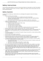
xStack® DGS-3120 Series Layer 3 Managed Gigabit Switch Hardware Installation Guide Safety Instructions Use the following If the system gets wet, see the appropriate section in the troubleshooting guide or contact your trained service provider. • Do not push any objects into the openings of the - D-Link DGS-3120-24PC-SI | Hardware Installation Guide - Page 7
DGS-3120 Series Layer 3 Managed Gigabit Switch Hardware Installation Guide -48VDC input connector of the DGS-3120-24SC-DC has no protective cage as to various peripherals or supporting hardware. CAUTION: Installing systems on or stand on any component when servicing other components in a rack. NOTE: - D-Link DGS-3120-24PC-SI | Hardware Installation Guide - Page 8
xStack® DGS-3120 Series Layer 3 Managed Gigabit Switch Hardware Installation Guide CAUTION: The system chassis must be positively grounded to the rack cabinet frame. Do not attempt to connect power to the system until grounding cables - D-Link DGS-3120-24PC-SI | Hardware Installation Guide - Page 9
/100/1000BASE-T/SFP ports L3 Managed Switch • DGS-3120-24PC: 20 Ethernet 10/100/1000 Ports + 4 combo 10/100/1000BASE-T/SFP ports PoE L3 Managed Switch • DGS-3120-48PC: 44 Ethernet 10/100/1000 Ports + 4 combo 10/100/1000BASE-T/SFP ports PoE L3 Managed Switch • DGS-3120-24SC: 16 SFP ports + 8 combo 10 - D-Link DGS-3120-24PC-SI | Hardware Installation Guide - Page 10
DGS-3120 Series Layer 3 Managed Gigabit Switch Hardware Installation Guide Features The list below highlights the significant protocols and features supported by the Switch compliant • IEEE 802.1p Priority Queues • IEEE 802.3ad Link Aggregation Control Protocol • IEEE 802.1X Port-based and Host- - D-Link DGS-3120-24PC-SI | Hardware Installation Guide - Page 11
xStack® DGS-3120 Series Layer 3 Managed Gigabit Switch Hardware Installation Guide • Port Mirroring • LLDP • NLB • Traffic segmentation • D-Link Safeguard Engine VRRP) • Protocol Independent Multicast (DM, SM, SSM, Sparse-Dense) • MIB support for: o RFC 1213 MIB II o RFC 4188 Bridge MIB o RFC 1907 - D-Link DGS-3120-24PC-SI | Hardware Installation Guide - Page 12
xStack® DGS-3120 Series Layer 3 Managed Gigabit Switch Hardware Installation Guide Ports DGS-3120-24TC DGS-3120-24SC DGS-3120-24SC-DC DGS-3120-24PC DGS-3120-48TC DGS-3120-48PC Twenty-four Copper ports (10/100/1000Mbps). Four Combo Copper/SFP ports (10/100/1000Mbps and 100/1000Mbps). Two dedicated, - D-Link DGS-3120-24PC-SI | Hardware Installation Guide - Page 13
in more detail. The DGS-3120-24PC and DGS-3120-48PC switches are equipt with an additional PoE light, to indication whether the ports are running in Power over Ethernet mode. Figure 1-1 Front panel view of the DGS-3120-24TC Figure 1-2 Front panel view of the DGS-3120-24SC Figure 1-3 Front panel view - D-Link DGS-3120-24PC-SI | Hardware Installation Guide - Page 14
DGS-3120-24PC and DGS3120-48PC switches are equipt with an additional PoE light, to indication whether the ports are running in Power over Ethernet mode. Figure 1-7 LED indicators for the DGS-3120-24TC Figure 1-8 LED indicators for the DGS-3120-24SC Figure 1-9 LED indicators for the DGS-3120-24SC - D-Link DGS-3120-24PC-SI | Hardware Installation Guide - Page 15
LED in not available on the DGS-3120-24SC-DC switch. For standalone Switches, this will light green. For stacked Switches, a solid Green light indicates this unit is the Master of the stack. A solid green stacking port 1 LED indicates there is a secure connection (or link) to an Ethernet device at - D-Link DGS-3120-24PC-SI | Hardware Installation Guide - Page 16
DGS-3120 Series Layer 3 Managed Gigabit Switch Hardware Installation Guide S2 Fan SD Stack ID Link/Act LEDs PoE A solid green stacking port 2 LED indicates there is a secure connection (or link is no link or activity. Only the DGS-3120-24PC and the DGS-3120-48PC switches are equipt with a PoE LED. - D-Link DGS-3120-24PC-SI | Hardware Installation Guide - Page 17
Managed Gigabit Switch Hardware Installation Guide Rear Panel Description The rear panel contains an AC power connector, an outlet for an external redundant power supply, and two stacking ports. Figure 1-13 Rear panel view of the DGS-3120-24TC Figure 1-14 Rear panel view of the DGS-3120-24SC Figure - D-Link DGS-3120-24PC-SI | Hardware Installation Guide - Page 18
xStack® DGS-3120 Series Layer 3 Managed Gigabit Switch Hardware Installation Guide stacking. The Switch supports a stacking cable length of DGS-3120-24TC, DGS-3120-24SC, and DGS-3120-24SC-DC Figure 1-20 Identical side panels of the DGS-3120-24PC Figure 1-21 Identical side panels of the DGS-3120-48TC - D-Link DGS-3120-24PC-SI | Hardware Installation Guide - Page 19
xStack® DGS-3120 Series Layer 3 Managed Gigabit Switch Hardware Installation Guide Chapter 2 Installation Package Contents Installation Guidelines Power On (AC Power) Connection DC Power to the DGS-3120-24SC-DC Insatalling SFP Ports Connecting to a Redundant Power Supply External Redundant Power - D-Link DGS-3120-24PC-SI | Hardware Installation Guide - Page 20
xStack® DGS-3120 Series Layer 3 Managed Gigabit Switch Hardware Installation Guide Installing the Switch without a Rack First, attach the rubber feet included with the Switch if installing on a desktop or shelf. Attach these cushioning feet on the bottom at each corner of the device. Allow enough - D-Link DGS-3120-24PC-SI | Hardware Installation Guide - Page 21
xStack® DGS-3120 Series Layer 3 Managed Gigabit Switch Hardware Installation Guide Mounting the Switch in a Standard 19" Rack Figure 2-3 Installing the Switch in a rack Power On (AC Power) 1. Plug one end of the AC power cord into the power connector of the Switch and the other end into the local - D-Link DGS-3120-24PC-SI | Hardware Installation Guide - Page 22
xStack® DGS-3120 Series Layer 3 Managed Gigabit Switch Hardware Installation Guide Connecting DC Power to the DGS-3120-24SC-DC Follow the instructions below to connect the DC power supply of the DGS-3120-24SC-DC This equipment must be installed and maintained by qualified service personnel only. 14 - D-Link DGS-3120-24PC-SI | Hardware Installation Guide - Page 23
xStack® DGS-3120 Series Layer 3 Managed Gigabit Switch Hardware Installation Guide Installing SFP Ports The Switch is equipped with SFP (Small Form Factor Portable) ports, which are used with fiber-optical transceiver cabling.SFP ports support full-duplex transmissions, auto-negotiation, and can be - D-Link DGS-3120-24PC-SI | Hardware Installation Guide - Page 24
Guide for more information. CAUTION: DO NOT use the DGS-3120-24TC/24SC switch with any redundant power system other than the DPS-200. CAUTION: DO NOT use the DGS-3120-48TC switch with any redundant power system other than the DPS-500 and the DPS-500DC. CAUTION: DO NOT use the DGS-3120-24PC - D-Link DGS-3120-24PC-SI | Hardware Installation Guide - Page 25
the switches being supported. The DPS-200 and DPS-500 can both be installed into a DPS-900, or DPS-800 rack mount unit. The DPS-200 can only be used with the DGS-3120-24TC and the DGS-3120-24SC. The DPS-500 can only be used with the DGS-3120-48TC. The DPS-700 can only be used with the DGS-3120-24PC - D-Link DGS-3120-24PC-SI | Hardware Installation Guide - Page 26
xStack® DGS-3120 Series Layer 3 Managed Gigabit Switch Hardware Installation Guide NOTE: See the RPS Quick Installation Guide for more information. Figure 2-8 Rear view of the DPS-700 connected to a DGS-3120-24PC CAUTION: Do not connect the DPS-700 to the DGS-3120-24PC/48PC by using the 14-pin DC - D-Link DGS-3120-24PC-SI | Hardware Installation Guide - Page 27
xStack® DGS-3120 Series Layer 3 Managed Gigabit Switch Hardware Installation Guide The RPS can be mounted in a standard 19" rack. Use the following diagram to guide you. Figure 2-10 Installing the DPS-800 in an Equipment Rack DPS-900 The DPS-900 is a standard-size rack mount (5 standard units in - D-Link DGS-3120-24PC-SI | Hardware Installation Guide - Page 28
xStack® DGS-3120 Series Layer 3 Managed Gigabit Switch Hardware Installation Guide The RPS can be mounted in a standard 19" rack. Use the following diagram to guide you. Figure 2-12 Installing the DPS-900 into the equipment rack CAUTION: Installing systems in a rack without the front and side - D-Link DGS-3120-24PC-SI | Hardware Installation Guide - Page 29
xStack® DGS-3120 Series Layer 3 Managed Gigabit Switch Hardware Installation Guide Chapter 3 Connecting the Switch Switch to End Node Switch to Switch Connecting to Network Backbone or Server NOTE: All high-performance N-Way Ethernet ports can support both MDI-II and MDI-X connections. Switch to - D-Link DGS-3120-24PC-SI | Hardware Installation Guide - Page 30
xStack® DGS-3120 Series Layer 3 Managed Gigabit Switch Hardware Installation Guide Switch to Switch There is a great deal of flexibility on how connections are made using the appropriate cabling. • Connect a 10BASE-T switch port to the Switch via a twisted-pair Category 3, 4 or 5 UTP/STP cable. • - D-Link DGS-3120-24PC-SI | Hardware Installation Guide - Page 31
xStack® DGS-3120 Series Layer 3 Managed Gigabit Switch Hardware Installation Guide Connecting to Network the type of port. A valid connection is indicated when the Link LED is lit. xStack Power S1 Console S2 RPS Fan Master SD DGS-3120-24TC 10/100M 1000M Link Act 1 2 3 4 5 6 7 8 9 10 - D-Link DGS-3120-24PC-SI | Hardware Installation Guide - Page 32
xStack® DGS-3120 Series Layer 3 Managed Gigabit Switch Hardware Installation Guide Chapter 4 Introduction to Switch Management Management Options Connecting the Console Port First Time Connecting to the Switch Password Protection IP Address Assignment SNMP Settings Management Options This system may - D-Link DGS-3120-24PC-SI | Hardware Installation Guide - Page 33
on setting up user accounts. See the DGS-3120 Series CLI Reference Guide on the documentation CD for a list of all commands and additional information on using the CLI. • To end a management session, use the logout command or close the emulator program. If problems occur in making this connection on - D-Link DGS-3120-24PC-SI | Hardware Installation Guide - Page 34
Management port connection. Upon initial connection to the Switch, the login screen appears (see example below). DGS-3120-24TC Gigabit Ethernet Switch Command Line Interface UserName: Firmware: Build 3.00.010 Copyright(C) 2013 D-Link Corporation. All rights reserved. Figure 4-2 Initial screen - D-Link DGS-3120-24PC-SI | Hardware Installation Guide - Page 35
xStack® DGS-3120 Series Layer 3 Managed Gigabit Switch Hardware Installation Guide IP Address Assignment An IP address must be assigned to each switch, which is used for communication with an SNMP network manager or other TCP/IP application (for example BOOTP, TFTP). The Switch's default IP address - D-Link DGS-3120-24PC-SI | Hardware Installation Guide - Page 36
DGS-3120 Series Layer 3 Managed Gigabit Switch Hardware Installation Guide Traps Traps are messages that alert network personnel of events that occur on the Switch. The events can be as serious as a reboot (someone accidentally turned OFF the Switch -II, the Switch also supports its own proprietary - D-Link DGS-3120-24PC-SI | Hardware Installation Guide - Page 37
xStack® DGS-3120 Series Layer 3 Managed Gigabit Switch Hardware Installation Guide Chapter 5 Web-based Switch Configuration Introduction Logging onto the Web Manager Web-based User Interface Web Pages Introduction Most software functions of the Switch can be managed, configured, and monitored via - D-Link DGS-3120-24PC-SI | Hardware Installation Guide - Page 38
DGS-3120 Series Layer 3 Managed Gigabit Switch Hardware Installation Guide Web-based User Interface The user interface provides access to various Switch D-Link logo to go to the D-Link website. Presents a graphical near real-time image of the front panel of the Switch. This area displays the Switch's - D-Link DGS-3120-24PC-SI | Hardware Installation Guide - Page 39
xStack® DGS-3120 Series Layer 3 Managed Gigabit Switch Hardware Installation Guide Web Pages When connecting to the management mode of the Switch with a Web browser, a login screen is displayed. There is no default user name or password necessary to access the Switch's management mode. NOTE: Be sure - D-Link DGS-3120-24PC-SI | Hardware Installation Guide - Page 40
DGS-3120 Series Layer 3 Managed Gigabit Switch Hardware Installation Guide 802.3ad Link Aggregation DGS-3120-24SC-DC: Sixteen SFP ports (100/1000Mbps), Eight Combo Copper/SFP ports (10/100/1000Mbps and 100/1000Mbps), Two dedicated, high speed stacking ports. DGS-3120-24PC: Twenty-four Copper PoE - D-Link DGS-3120-24PC-SI | Hardware Installation Guide - Page 41
: DGS-3120-24TC/24SC DPS-500/DPS-500DC: DGS-3120-48TC DPS-700: DGS-3120-24PC/48PC DGS-3120-24TC: 35.5 Watts (Max.) DGS-3120-24SC: 33.5 Watts (Max.) DGS-3120-24SC-DC: 32.5 Watts (Max.) DGS-3120-24PC with 370W PoE load: 488.3 Watts (Max.) DGS-3120-24PC with 740W PoE load: 913.5 Watts (Max.) DGS-3120 - D-Link DGS-3120-24PC-SI | Hardware Installation Guide - Page 42
EI and SI Mode Only) Virtual Stacking / Clustering DGS-3120-24PC: 65.48 million packets per second. DGS-3120-48TC: 101.19 million packets per second. DGS-3120-48PC: 101.19 million packets per second. DGS-3120-24TC: 88Gbps DGS-3120-24SC: 88Gbps DGS-3120-24SC-DC: 88Gbps DGS-3120-24PC: 88Gbps DGS-3120 - D-Link DGS-3120-24PC-SI | Hardware Installation Guide - Page 43
two modes in turn for all 10/100/1000Mbps ports on DGS-3120-24PC/48PC: - Link/Act/Speed Mode - PoE Mode Green Solid Light A LED Mode Select Button to switch Link/Act/Speed Mode Solid Light A LED Mode Select Button to switch PoE Mode Green Solid Light When there is a secure connection (or - D-Link DGS-3120-24PC-SI | Hardware Installation Guide - Page 44
xStack® DGS-3120 Series Layer 3 Managed Gigabit Switch Hardware Installation Guide Port Functions Feature Console DEM-220R (100BASE-BX-U, TX-1310/RX-1550 nm, Single-mode, 20km) • Supports IEEE 802.3af PoE and IEEE 802.3at PoE+ compliance. • Supplies power to PD devices up to 15.4W per port (802. - D-Link DGS-3120-24PC-SI | Hardware Installation Guide - Page 45
xStack® DGS-3120 Series Layer 3 Managed Gigabit Switch Hardware Installation Guide Class 0 1 2 3 4 Usage Default .3af devices; or CAT5e~6A UTP cables for 802.3at devices. • The DGS-3120-24PC and DGS-3120-48PC works with all D-Link 802.3af and 802.3at capable devices They also works with all non-802 - D-Link DGS-3120-24PC-SI | Hardware Installation Guide - Page 46
xStack® DGS-3120 Series Layer 3 Managed Gigabit Switch Hardware Installation Guide Appendix B - Cables and Connectors Ethernet Cable When connecting the Switch to another switch, a bridge or hub, a normal cable is necessary. Please review these products for matching cable pin assignment. The - D-Link DGS-3120-24PC-SI | Hardware Installation Guide - Page 47
xStack® DGS-3120 Series Layer 3 Managed Gigabit Switch Hardware Installation Guide Console Cable When connecting the Switch a PC, a Console cable is necessary. The following diagrams and tables show the standard Console-to-DJ-45 receptacle/connector and their pin assignments. Figure B-2 Console- - D-Link DGS-3120-24PC-SI | Hardware Installation Guide - Page 48
xStack® DGS-3120 Series Layer 3 Managed Gigabit Switch Hardware Installation Guide Redundant Power Supply (RPS) Cable When connecting the Switch to a Redundant Power Supply, an RPS cable is necessary. Please review these products for matching cable pin assignment.The following diagrams and tables - D-Link DGS-3120-24PC-SI | Hardware Installation Guide - Page 49
xStack® DGS-3120 Series Layer 3 Managed Gigabit Switch Hardware Installation Guide RPS 14-pin DC Power Cable Pin Assignments Pin Device DPS-500 1 NC NC 2 GND GND 3 GND GND 4 GND GND 5 GND GND 6 +12V +12V 7 +12V + - D-Link DGS-3120-24PC-SI | Hardware Installation Guide - Page 50
xStack® DGS-3120 Series Layer 3 Managed Gigabit Switch Hardware Installation Guide 22-pin DC power cable Figure B-4 Redundant Power Supply (RPS) 22-pin DC Power Cable RPS 22-pin DC Power Cable Pin Assignments Pin Device - D-Link DGS-3120-24PC-SI | Hardware Installation Guide - Page 51
xStack® DGS-3120 Series Layer 3 Managed Gigabit Switch Hardware Installation Guide Appendix C - Module Specs and Cable Lengths Use the following table to as a guide for the module specs and maximum cable lengths. Standard Mini-GBIC 1000BASE-T 100BASE-TX 10BASE-T DEM-310GT DEM-311GT DEM-312GT2 DEM- - D-Link DGS-3120-24PC-SI | Hardware Installation Guide - Page 52
covered in the operating manual for the product, and normal maintenance; Damage that occurs in shipment, due to act of God, failures due to power surge, and cosmetic damage; Any hardware, software, firmware or other products or services provided by anyone other than D-Link; and Products that have - D-Link DGS-3120-24PC-SI | Hardware Installation Guide - Page 53
LINK FOR WARRANTY SERVICE) RESULTING FROM THE USE OF THE PRODUCT, RELATING TO WARRANTY SERVICE, OR ARISING OUT OF ANY BREACH OF THIS WARRANTY, EVEN IF D-LINK LINK UNDER THIS WARRANTY IS LIMITED TO THE PURCHASE PRICE Link Corporation/D-Link Systems, Inc., as stipulated by the United the instructions, - D-Link DGS-3120-24PC-SI | Hardware Installation Guide - Page 54
Product Registration Register your D-Link product online at http://support.dlink.com/register/ Product registration is entirely voluntary and failure to complete or return this form will not diminish your warranty rights. - D-Link DGS-3120-24PC-SI | Hardware Installation Guide - Page 55
Tech Support Technical Support You can find software updates and user documentation on the DLink website. D-Link provides free technical support for customers within the United States and within Canada for the duration of the service period, and warranty confirmation service, during the warranty - D-Link DGS-3120-24PC-SI | Hardware Installation Guide - Page 56
Support United Kingdom (Mon-Fri) Home Wireless/Broadband 0871 873 3000 (9.00am-06.00pm, Sat 10.00am-02.00pm) Managed, Smart, & Wireless Switches , €0.045ppm off peak Times Internet http://dlink.com Technische Unterstützung Deutschland: Web: Telefon: Zeiten: http://dlink.com +49(0)1805 2787 0,14 € - D-Link DGS-3120-24PC-SI | Hardware Installation Guide - Page 57
Asistencia Técnica Asistencia Técnica Telefónica de D-Link: +34 902 30 45 45 0,067 €/min De Lunes a Viernes de 9:00 a 19:00 http://dlink.com Supporto tecnico Supporto Tecnico dal lunedì al : http://dlink.com / 0107994325 / €0.15per minuut. Tech Support for customers within Belgium: http://dlink.com / - D-Link DGS-3120-24PC-SI | Hardware Installation Guide - Page 58
HUG/min - Mobile 49.99,HUF/min email : [email protected] URL : http://dlink.com Teknisk Support D-Link Teknisk Support over Internett: http://dlink.com D-Link Teknisk telefonsupport: 815 69 755 (Hverdager 08:00 - 17:00) Teknisk Support D-Link teknisk support over telefonen: Tlf.: 702 690 40 Normale - D-Link DGS-3120-24PC-SI | Hardware Installation Guide - Page 59
57 Teknisk Support D-Link Teknisk Support via Internet: http://dlink.com D-Link Teknisk Support via telefon: 0770-33 00 35 Vardagar 08:00 - 17:00 Assistência Técnica Assistência Técnica da D-Link na Internet: http://dlink.com e-mail: [email protected] D-Link Hellas Support Center http://dlink.com - D-Link DGS-3120-24PC-SI | Hardware Installation Guide - Page 60
, podporo ter navodila za uporabo prosimo obiščite D-Link - ovo spletno stran www.dlink.eu http://dlink.com Suport tehnic Vă mulţumim pentru alegerea produselor D-Link. Pentru mai multe informaţii, suport şi manuale ale produselor vă rugăm să vizitaţi site-ul D-Link www.dlink.eu http://dlink.com - D-Link DGS-3120-24PC-SI | Hardware Installation Guide - Page 61
You can find software updates and user documentation on the D-Link website. Tech Support for customers in Australia: Tel: 1300-766-868 24/7 Technical Support Web: http://www.dlink.com.au E-mail: [email protected] India: Tel: +91-22-27626600 Toll Free 1800-22-8998 Web: www.dlink.co.in E-Mail - D-Link DGS-3120-24PC-SI | Hardware Installation Guide - Page 62
updates and user documentation on the D-Link website. Tech Support for customers in Iran Unit 5, 5th Floor, No. 20, 17th Alley , Bokharest St. , Argentine Sq. , Tehran IRAN Postal Code : 1513833817 Tel: +98-21-88880918,19 +98-21-88706653,54 General Inquiries: [email protected] Tech Support - D-Link DGS-3120-24PC-SI | Hardware Installation Guide - Page 63
D-Link. D-Link D-Link D-Link: 8-800-700-5465 http://www.dlink.ru e-mail: [email protected] Офисы 129626 14 Тел.: +7 (495) 744-0099 04080 87 18 Тел.: +38 (044) 545-64-40 E-mail: [email protected] 220114 169 , БЦ "XXI 375(17) 218-13-65 E-mail: [email protected] 050008 143 T 7 727 - D-Link DGS-3120-24PC-SI | Hardware Installation Guide - Page 64
Usted puede encontrar actualizaciones de softwares o firmwares y documentación para usuarios a través de nuestro sitio www.dlinkla.com SOPORTE TÉCNICO PARA USUARIOS EN LATINO AMERICA Soporte técnico a través de los siguientes teléfonos de D-Link PAIS Argentina Chile Colombia Costa Rica Ecuador - D-Link DGS-3120-24PC-SI | Hardware Installation Guide - Page 65
Suporte Técnico Caso tenha dúvidas na instalação do produto, entre em contato com o Suporte Técnico D-Link. Acesse o site: www.dlink.com.br/suporte - D-Link DGS-3120-24PC-SI | Hardware Installation Guide - Page 66
D-Link D-Link台灣 D-Link 0800-002-615 02)6600-0123#8715 9:00到晚上9:00 網 站:http://www.dlink.com.tw [email protected] D-Link http://www.dlink.com.tw - D-Link DGS-3120-24PC-SI | Hardware Installation Guide - Page 67
Dukungan Teknis Update perangkat lunak dan dokumentasi pengguna dapat diperoleh pada situs web D-Link. Dukungan Teknis untuk pelanggan: Dukungan Teknis D-Link melalui telepon: Tel: +62-21-5731610 Dukungan Teknis D-Link melalui Internet: Email : [email protected] Website : http://support.dlink.co. - D-Link DGS-3120-24PC-SI | Hardware Installation Guide - Page 68
Technical Support Web Web サイト URL:http://www.dlink-jp.com - D-Link DGS-3120-24PC-SI | Hardware Installation Guide - Page 69
技术支持 36 B 座 26F 02-05 100013 400-629-6688 028) 87300889 http://www.dlink.com.cn 400 9:00-19:00;节假日9:00-18:00. - D-Link DGS-3120-24PC-SI | Hardware Installation Guide - Page 70
Reseller's name Telephone Answers to the following questions help us to support your product: 1. Where and how will the product primarily be used Others 4. What network operating system(s) does your organization use ? D-Link LANsmart Novell NetWare NetWare Lite SCO Unix/Xenix PC NFS 3Com 3+Open - D-Link DGS-3120-24PC-SI | Hardware Installation Guide - Page 71
-
 1
1 -
 2
2 -
 3
3 -
 4
4 -
 5
5 -
 6
6 -
 7
7 -
8
-
9
-
10
-
11
-
12
-
13
-
14
-
15
-
16
-
17
-
18
-
19
-
20
-
21
-
22
-
23
-
24
-
25
-
26
-
27
-
28
-
29
-
30
-
31
-
32
-
33
-
34
-
35
-
36
-
37
-
38
-
39
-
40
-
41
-
42
-
43
-
44
-
45
-
46
-
47
-
48
-
49
-
50
-
51
-
52
-
53
-
54
-
55
-
56
-
57
-
58
-
59
-
60
-
61
-
62
-
63
-
64
-
65
-
66
-
67
-
68
-
69
-
70
-
71
 |
 |