D-Link DIS-100G-5PSW Quick Installation Guide 1
D-Link DIS-100G-5PSW Manual
 |
View all D-Link DIS-100G-5PSW manuals
Add to My Manuals
Save this manual to your list of manuals |
D-Link DIS-100G-5PSW manual content summary:
- D-Link DIS-100G-5PSW | Quick Installation Guide 1 - Page 1
Guide Overview The DIS-100G unmanaged Industrial Gigabit Ethernet Switch solutions are designed for supporting standard DC power terminal block 1 Quick Installation Guide 1 Safety Instructions When a connector is removed during installation, testing, or servicing, or when an energized fiber is - D-Link DIS-100G-5PSW | Quick Installation Guide 1 - Page 2
DIS-100G-5W DIS-100G-5SW DIS-100G-5PSW Ground Connecting The switch must be properly grounded for optimum system performance. DIS-100G-5W DIS-100G-5SW DIS-100G-5PSW Ethernet Interface Connecting (RJ45 Ethernet) The switches provide two types of electrical (RJ45) and optical (mini-GBIC) - D-Link DIS-100G-5PSW | Quick Installation Guide 1 - Page 3
Pin No# DIS-100G-5S Status DIS-100G-5SW DIS-100G-5PSW Pin 1 ON manual or visit http://support.dlink.com/ for more support. Online Support If there are any issues that are not in the user manual, please visit http://support.dlink.com/ which will direct you to your appropriate local D-Link support - D-Link DIS-100G-5PSW | Quick Installation Guide 1 - Page 4
service the product and never disassemble the product. For some products with user replaceable battery, please read and follow the instructions in the user manual conserve the environment and protect human health. D-Link and the Environment At D-Link, we understand and are committed to reducing any
-
 1
1 -
 2
2 -
 3
3 -
 4
4
 |
 |

1
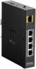
DIS-100G Series Unmanaged
Industrial Gigabit Ethernet
Switch
Quick Installation Guide
Overview
The DIS-100G unmanaged Industrial Gigabit Ethernet
Switch solutions are designed for supporting standard
industrial applications without complex setup to make the
network truly plug-and-play.
If the equipment is used in a manner not speci
fi
ed by the
manufacturer, the protection provided by the equipment
may be impaired.
Package Checklist
Please verify that the box contains the following items:
Item
Quantity
Unmanaged switch
1
Wall-mount plates
2
DIN-Rail kit
1
M4 Screws
(for the wall mount plates & DIN Rail kit)
4
DC power terminal block
1
Quick Installation Guide
1
Safety Instructions
When a connector is removed during installation, testing, or
servicing, or when an energized fiber is broken, a risk of
ocular exposure to optical energy that may be potentially
hazardous occurs, depending on the laser output power.
The primary hazards of exposure to laser radiation from an
optical-fiber communication system are:
Damage to the eye by accidental exposure to a beam
emitted by a laser source.
Damage to the eye from viewing a connector attached
to a broken fiber or an energized fiber.
Documentation Conventions
The following conventions are used in this quick installation
guide to emphasize information that will be of interest to the
reader.
Danger —
The described activity or situation might or
will cause
personal injury
.
Warning —
The described activity or situation might or
will cause
equipment damage
.
Caution —
The described activity or situation might or
will cause
service interruption
.
Note —
The information supplements the text or
highlights important points.
DIN-Rail Mounting
Mounting step:
1.
Screw the DIN-Rail bracket on with the bracket and
screws in the accessory kit.
2.
Hook the unit over the DIN rail.
3.
Push the bottom of the unit towards the DIN Rail until it
snaps into place.
Wall Mounting
(unit: mm)
Mounting step:
1.
Screw on the wall-mount plate on with the plate and
M4 screws in the accessory kit.
2
3