D-Link DSN-6020 User Manual for DSN-6410
D-Link DSN-6020 Manual
 |
View all D-Link DSN-6020 manuals
Add to My Manuals
Save this manual to your list of manuals |
D-Link DSN-6020 manual content summary:
- D-Link DSN-6020 | User Manual for DSN-6410 - Page 1
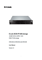
D-Link iSCSI IP SAN storage 10GbE iSCSI to SATA II / SAS RAID IP SAN storage DSN-6410 & DSN-6410 with DSN-640 User Manual Version 1.0 1 - D-Link DSN-6020 | User Manual for DSN-6410 - Page 2
in DSN-6410. Caution Do not attempt to service, change, disassemble or upgrade the equipment's components by yourself. Doing so may violate your warranty and expose you to electric shock. Refer all servicing to authorized service personnel. Please always follow the instructions in this user's manual - D-Link DSN-6020 | User Manual for DSN-6410 - Page 3
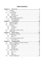
Table of Contents Chapter 1 Overview 6 1.1 Features 6 1.1.1 Highlights...7 1.2 RAID concepts 8 1.2.1 1.2.2 1.2.3 Terminology...8 RAID levels ...10 Volume relationship 11 1.3 iSCSI concepts 12 1.4 IP SAN storage specifications 13 1.4.1 1.4.2 Technical specifications 13 FCC and CE - D-Link DSN-6020 | User Manual for DSN-6410 - Page 4
105 5.8 MPIO and MC/S 106 5.9 Trunking and LACP 108 5.10 Dual controllers (only for DSN-6410 with DSN-640 109 5.10.1 Perform I/O ...109 5.10.2 Ownership ...110 5.10.3 Controller status ...111 5.11 Replication 112 5.12 VLAN 122 Chapter 6 Troubleshooting 125 6.1 System buzzer 125 4 - D-Link DSN-6020 | User Manual for DSN-6410 - Page 5
6.2 Event notifications 125 Appendix 133 A. Certification list 133 B. Microsoft iSCSI initiator 136 C. From Single controller to Dual Controller 142 5 - D-Link DSN-6020 | User Manual for DSN-6410 - Page 6
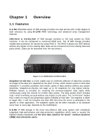
storage provides non-stop service with a high degree of fault tolerance by using D-LINK RAID technology and advanced array management features. DSN-6410 & 6410w/640 snapshot copies can be taken manually or by schedule every hour or every day, depends on the modification. D-LINK IP SAN storage is the - D-Link DSN-6020 | User Manual for DSN-6410 - Page 7
LINK DSN-6410 & 6410w/640 feature highlights Host Interface 4 x 10GbE iSCSI ports (DSN-6410 with DSN-640) 2 x 10GbE iSCSI ports (DSN-6410) Drive Interface 12 x SAS or SATA II RAID Controllers Dual-active RAID controllers (DSN-6410 with DSN Load balancing and failover support on the 4 x 10GbE - D-Link DSN-6020 | User Manual for DSN-6410 - Page 8
1.2 RAID concepts RAID is the abbreviation of "Redundant Array of Independent Disks". The basic idea of RAID is to combine multiple drives together to form one large logical drive. This RAID drive obtains performance, capacity and reliability than a single drive. The operating system detects the - D-Link DSN-6020 | User Manual for DSN-6410 - Page 9
virtual disks. Small Computer Systems Interface. Serial Attached SCSI. Self-Monitoring Analysis and Reporting Technology. World Wide Name. Host Bus Adapter. SCSI Enclosure Services. Network Interface Card. Battery Backup Module • Part 2: iSCSI iSCSI LACP Internet Small Computer Systems Interface - D-Link DSN-6020 | User Manual for DSN-6410 - Page 10
an iSCSI storage system over the iSCSI data ports. Internet Storage Name Service. • Part 3: Dual controller SBB Storage Bridge Bay. The objective enclosure management requirements for an enclosure controller slot that will support a variety of storage controllers from a variety of independent - D-Link DSN-6020 | User Manual for DSN-6410 - Page 11
The abbreviation of "Just a Bunch Of Disks". JBOD needs at least one hard drive. 1.2.3 Volume relationship The below graphic is the volume structure which D-LINK has designed. It describes the relationship of RAID components. One RG (RAID group) consists of a set of VDs (Virtual Disk) and owns one - D-Link DSN-6020 | User Manual for DSN-6410 - Page 12
concepts iSCSI (Internet SCSI) is a protocol which encapsulates SCSI (Small Computer System Interface) commands and data in TCP/IP packets for linking storage devices with servers over common IP infrastructures. iSCSI provides high performance SANs over standard IP networks like LAN, WAN or the - D-Link DSN-6020 | User Manual for DSN-6410 - Page 13
manual. Microsoft, Linux, Solaris and Mac provide iSCSI initiator driver. Please contact DLINK for the latest certification list. Below are the available links: 1. Link • Controller features 1. Dual-active configuration support (only for DSN-6410 with DSN-640) 2. Better performance, when comparing - D-Link DSN-6020 | User Manual for DSN-6410 - Page 14
down time (only for DSN-6410 with DSN640) 7. Multiple target iSCSI nodes per controller support Each LUN can JBOD expansion port for expansion 10. Multiplexer board support for SATA drives (optional, on Dual controller mode usage 6. Multiple RAID volumes support 7. Configurable RAID stripe size - D-Link DSN-6020 | User Manual for DSN-6410 - Page 15
with rollback enabled Snapshot enabled up to 16 volumes, each logical volume supports up to 32 snapshot volumes, total 512 snapshot volumes per system 2. Microsoft Windows Volume Shadow Copy Services (VSS) 3. Configurable N-way mirror for high data protection 4. Online disk roaming 5. Instant - D-Link DSN-6020 | User Manual for DSN-6410 - Page 16
-Only 3. Up to 128 sessions per controller 4. One logic volume can be shared by as many as 16 hosts • OS support Windows Linux Solaris Mac • Drive support 1. SAS 2. SATA II (optional) 3. SCSI-3 compliant 4. Multiple IO transaction processing 5. Tagged command queuing 6. Disk auto spin-down - D-Link DSN-6020 | User Manual for DSN-6410 - Page 17
-E Technical Standard: EMC DIRECTIVE 2004/108/EC (EN55022 / EN55024) UL statement Rack Mount Instructions - The following or similar rack-mount instructions are included with the installation instructions: A. Elevated Operating Ambient - If installed in a closed or multi-unit rack assembly, the - D-Link DSN-6020 | User Manual for DSN-6410 - Page 18
This equipment intended for installation in restricted access location. Access can only be gained by SERVICE PERSONS or by USERS who have been instructed about the reasons for the restrictions applied to the location and about any precautions that shall be taken. Access is through the use - D-Link DSN-6020 | User Manual for DSN-6410 - Page 19
10GbE switches with LCAP / Trunking (optional). 6. CHAP security information, including CHAP username and secret (optional). 2.3 Enclosure 2.3.1 Front view Figure 2.3.1.1 (DSN-6410 & 6410w/640) Drive slot numbering Slot 1 Slot 2 Slot 3 Slot 4 Slot 5 Slot 6 Slot 7 Slot 8 Slot 9 19 Slot 10 Slot - D-Link DSN-6020 | User Manual for DSN-6410 - Page 20
The drives can be installed into any slot in the enclosure. Slot numbering will be reflected in web UI. Tips It is advisable to install at least one drive in slots 1 ~ 4. System event logs are saved to drives in these slots; If no drives are fitted the event logs will be lost in the event of a - D-Link DSN-6020 | User Manual for DSN-6410 - Page 21
populated with drives. To install SAS or SATA drives with no Bridge Board use the front mounting holes: To install SATA drives with Bridge Board (DSN-654), fit the Bridge Board first Then install the drive using the rear mounting holes: 21 - D-Link DSN-6020 | User Manual for DSN-6410 - Page 22
. Off No HDD. HDD access LED: Blue blinking HDD is accessing. Off No HDD. HDD tray handhold. Latch for tray kit removal. 2.3.4 Rear view Figure 2.3.4.1 (DSN-6410 with DSN-640 SFP+) • PSU and Fan module description: 22 - D-Link DSN-6020 | User Manual for DSN-6410 - Page 23
Controller 2. (only on DSN-6410 with DSN-640) Controller 1. Power supply unit (PSU1). Fan module (FAN1 / FAN2). Power supply unit (PSU2). Fan module (FAN3 / FAN4). 23 - D-Link DSN-6020 | User Manual for DSN-6410 - Page 24
Figure 2.3.4.3 (DSN-6410 SFP+) • Connector, LED and button description: 10GbE ports (x2). Link LED: Orange Asserted when a 1G link is established and maintained. Blue Asserted when a 10G link is establish and maintained. Access LED: Yellow Asserted when the link is established - D-Link DSN-6020 | User Manual for DSN-6410 - Page 25
Install battery backup module To install the IP SAN storage with a battery backup module, please follow the procedure. Figure 2.4.1 1. BBM (Battery Backup Module) supports hot pluggable. Regardless of the IP SAN storage is turned on or off. 2. Remove the cover of BBM. 3. Insert the BBM. 4. Tighten - D-Link DSN-6020 | User Manual for DSN-6410 - Page 26
2.5 Deployment Please refer to the following topology and have all the connections ready. Figure 2.5.1 (DSN-6410 with DSN-640) Figure 2.5.2 (DSN-6410) 1. Setup the hardware connection before power on servers. Connect console cable, management port cable, and iSCSI data port cables in advance. 26 - D-Link DSN-6020 | User Manual for DSN-6410 - Page 27
(both controller 1 and controller 2), and then MPIO should be setup automatically. (only for DSN-6410 with DSN-640) Tips iSNS server is recommended for dual controller system. For better data service availability, all the connections among host servers, 10GbE switches, and the dual controllers are - D-Link DSN-6020 | User Manual for DSN-6410 - Page 28
Figure 2.5.4 1. Using RS-232 cable for console (back color, phone jack to DB9 female) to connect from controller to management PC directly. 2. Using RS-232 cable for UPS (gray color, phone jack to DB9 male) to connect from controller to APC Smart UPS serial cable (DB9 female side), and then connect - D-Link DSN-6020 | User Manual for DSN-6410 - Page 29
console Use console cable (NULL modem cable) to connect from console port of D-LINK IP SAN storage to RS 232 port of management PC. Please refer to Login name: admin Default password: 123456 Tips D-LINK product supports SSH for remote control only. For using SSH, the IP address and password are - D-Link DSN-6020 | User Manual for DSN-6410 - Page 30
3.1.3 Web UI D-LINK IP SAN storage supports graphic user interface (GUI) to operate. Be sure to connect the LAN cable. The default IP setting is DHCP; open the browser and enter: http:// - D-Link DSN-6020 | User Manual for DSN-6410 - Page 31
• Indicator description: RAID light: Green RAID works well. Red RAID fails. Temperature light: Green Temperature is normal. Red Temperature is abnormal. Voltage light: Green voltage is normal. Red voltage is abnormal. UPS light: Green UPS works well. Red UPS fails. - D-Link DSN-6020 | User Manual for DSN-6410 - Page 32
. The default value is enabled, but some applications will disable it. 3.2 How to use the system quickly The following methods will describe the quick guide to use this IP SAN storage. 3.2.1 Quick installation Please make sure that there are some free drives installed in this system. SAS drivers are - D-Link DSN-6020 | User Manual for DSN-6410 - Page 33
Figure 3.2.1.2 Step2: Confirm the management port IP address and DNS, and then click "Next". Figure 3.2.1.3 Step 3: Set up the data port IP and click "Next". 33 - D-Link DSN-6020 | User Manual for DSN-6410 - Page 34
Figure 3.2.1.4 Step 4: Set up the RAID level and volume size and click "Next". Figure 3.2.1.5 Step 5: Check all items, and click "Finish". 34 - D-Link DSN-6020 | User Manual for DSN-6410 - Page 35
sizes. After user chooses RAID level, user may find that some HDDs are available (free status). The result is using smarter policy designed by DLINK. It gives user: 1. Biggest capacity of RAID level for user to choose and, 2. The fewest disk number for RAID level / volume size. E.g., user chooses - D-Link DSN-6020 | User Manual for DSN-6410 - Page 36
Figure 3.2.2.1 Step 2: Please select the combination of the RG capacity, or "Use default algorithm" for maximum RG capacity. After RG size is chosen, click "Next". Figure 3.2.2.2 36 - D-Link DSN-6020 | User Manual for DSN-6410 - Page 37
Step 3: Decide VD size. User can enter a number less or equal to the default number. Then click "Next". Figure 3.2.2.3 Step 4: Confirmation page. Click "Finish" if all setups are correct. Then a VD will be created. Step 5: Done. The system is available now. Figure 3.2.2.4 (Figure 3.2.2.4: A virtual - D-Link DSN-6020 | User Manual for DSN-6410 - Page 38
Date and time / System indication Network MAC address / Address / DNS / Port setting Login setting Login configuration / Admin password / User iSCSI configuration NIC Show information for:(Controller 1/ Controller 2) Link aggregation or multi-homed / IP settings for iSCSI ports / Become - D-Link DSN-6020 | User Manual for DSN-6410 - Page 39
Maintenance System System information information Event log Download / Mute / Clear Upgrade Browse the firmware to upgrade Firmware Synchronize the slave controller's firmware version with the synchronization master's Reset to factory Sure to reset to factory default? default Import and - D-Link DSN-6020 | User Manual for DSN-6410 - Page 40
Figure 4.2.1.1 Check "Change date and time" to set up the current date, time, and time zone before using or synchronize time from NTP (Network Time Protocol) server. Click "Confirm" in System indication to turn on the system indication LED. Click again to turn off. 4.2.2 Network setting "Network - D-Link DSN-6020 | User Manual for DSN-6410 - Page 41
Figure 4.2.2.1 4.2.3 Login setting "Login setting" can set single admin, auto logout time and admin / user password. The single admin is to prevent multiple users access the same system in the same time. 1. Auto logout: The options are (1) Disabled; (2) 5 minutes; (3) 30 minutes; (4) 1 hour. The - D-Link DSN-6020 | User Manual for DSN-6410 - Page 42
levels of event logs are needed to be sent via Mail. Default setting only enables ERROR and WARNING event logs. Please also make sure the DNS server IP is well-setup so the event notification mails can be sent successfully. 42 - D-Link DSN-6020 | User Manual for DSN-6410 - Page 43
Figure 4.2.4.1 4.2.5 Notification setting "Notification setting" can set up SNMP trap for alerting via SNMP, pop-up message via Windows messenger (not MSN), alert via syslog protocol, and event log filter for web UI and LCM notifications. 43 - D-Link DSN-6020 | User Manual for DSN-6410 - Page 44
necessary, click "Download" to get MIB file and import to SNMP. To use "Messenger", user must enable the service "Messenger" in Windows (Start Control Panel Administrative Tools Services Messenger), and then event logs can be received. It allows up to 3 messenger addresses. User can choose - D-Link DSN-6020 | User Manual for DSN-6410 - Page 45
Figure 4.3.1 4.3.1 NIC "NIC" can change IP addresses of iSCSI data ports. DSN-6410 & 6410w/640 has two 10GbE ports on each controller to transmit data. mode, or the link aggregation / trunking mode has been set up. When there are multiple data ports setting up in link aggregation or trunking mode - D-Link DSN-6020 | User Manual for DSN-6410 - Page 46
description of multi-homed / trunking / LACP functions. 1. Multi-homed: Default mode. Each of iSCSI data port is connected by itself and is not link aggregation and trunking. This function is also for Multipath functions. Select this mode can also remove the setting of Trunking / LACP in same time - D-Link DSN-6020 | User Manual for DSN-6410 - Page 47
iSCSI data ports on each controller, select at least two NICs for link aggregation.) Figure 4.3.1.4 For example, LAN1 and LAN2 are set as remove Trunking / LACP setting, check the gray button of LAN port, click "Delete link aggregation". Then it will pop up a message to confirm. • Ping host: - D-Link DSN-6020 | User Manual for DSN-6410 - Page 48
server IP address into iSNS server lists in order that iSCSI initiator service can send queries. The entity name can be changed. Figure 4.3.2.1 4.3.3 Node "Node" can view the target name for iSCSI initiator. DSN-6410 & 6410w/640 supports up to 32 multi-nodes. There are 32 default nodes created for - D-Link DSN-6020 | User Manual for DSN-6410 - Page 49
Figure 4.3.3.1 • CHAP: CHAP is the abbreviation of Challenge Handshake Authentication Protocol. CHAP is a strong authentication method used in point-to-point for user login. It's a type of authentication in which the authentication server sends the client a key to be used for encrypting the username - D-Link DSN-6020 | User Manual for DSN-6410 - Page 50
Figure 4.3.3.3 5. Go to "/ iSCSI configuration / CHAP account" page to create CHAP account. Please refer to next section for more detail. 6. Check the gray button of "OP." column, click "User". 7. Select CHAP user(s) which will be used. It's a multi option; it can be one or more. If choosing none, - D-Link DSN-6020 | User Manual for DSN-6410 - Page 51
• Rename alias: User can create an alias to one device node. 1. Check the gray button of "OP." column next to one device node. 2. Select "Rename alias". 3. Create an alias for that device node. 4. Click "OK" to confirm. 5. An alias appears at the end of that device node. Figure 4.3.3.6 Figure - D-Link DSN-6020 | User Manual for DSN-6410 - Page 52
of the session. (Figure 4.3.4.2: iSCSI Connection.) Figure 4.3.4.2 4.3.5 CHAP account "CHAP account" can manage a CHAP account for authentication. DSN-6410 with DSN-640/6410 can create multiple CHAP accounts. To setup CHAP account, please follow the procedures. 1. Click "Create". 2. Enter "User - D-Link DSN-6020 | User Manual for DSN-6410 - Page 53
3. Click "OK". Figure 4.3.5.1 Figure 4.3.5.2 4. Click "Delete" to delete CHAP account. 4.4 Volume configuration "Volume configuration" is designed for setting up the volume configuration which includes "Physical disk", "RAID group", "Virtual disk", "Snapshot", "Logical unit", and "Replication". - D-Link DSN-6020 | User Manual for DSN-6410 - Page 54
selected. For example, set PD slot number 4 to dedicated spare disk. Step 1: Check to the gray button of PD 4, select "Set Dedicated spare", it will link to next page. Figure 4.4.1.1 Step 2: If there is any RG which is in protected RAID level and can be set with dedicate spare disk, select - D-Link DSN-6020 | User Manual for DSN-6410 - Page 55
Figure 4.4.1.3 (Figure 4.4.1.3: Physical disks in slot 1,2,3 are created for a RG named "RG-R5". Slot 4 is set as dedicated spare disk of the RG named "RG-R5". The others are free disks.) Step 4: The unit of size can be changed from (GB) to (MB). It will display the capacity of hard drive in MB. - D-Link DSN-6020 | User Manual for DSN-6410 - Page 56
Usage Vendor Serial Type Write cache Standby Readahead Command queuing "Failed" the hard drive is failed. "Error Alert" S.M.A.R.T. error alert. "Read Errors" the hard drive has unrecoverable read errors. The usage of hard drive: "RAID disk" This hard drive has been set to a RAID - D-Link DSN-6020 | User Manual for DSN-6410 - Page 57
Set Dedicated Set a hard drive to dedicated spare of the selected RG. spares Upgrade Upgrade hard drive firmware. Disk Scrub Scrub the hard drive. Turn on/off the Turn on the indication LED of the hard drive. Click again to turn indication LED off. More information Show hard drive detail - D-Link DSN-6020 | User Manual for DSN-6410 - Page 58
Step 2: Confirm page. Click "OK" if all setups are correct. Figure 4.4.2.2 (Figure 4.4.2.2: There is a RAID 0 with 4 physical disks, named "RG-R0". The second RAID group is a RAID 5 with 3 physical disks, named "RG-R5".) Step 3: Done. View "RAID group" page. • RG column description: Name Total ( - D-Link DSN-6020 | User Manual for DSN-6410 - Page 59
can be executed when RG status is online. This is for online disk roaming purpose. Parity check Regenerate parity for the RAID group. It supports RAID 3 / 5 / 6 / 30 / 50 / 60. Delete Delete the RAID group. Set preferred owner Set the RG ownership to the other controller. Set disk Change the - D-Link DSN-6020 | User Manual for DSN-6410 - Page 60
property Write cache: "Enabled" Enable disk write cache. (Default) "Disabled" Disable disk write cache. Standby: "Disabled" Disable auto spin-down. (Default) "30 sec / 1 min / 5 min / 30 min" Enable hard drive auto spin-down to save power when no access after certain period of time. - D-Link DSN-6020 | User Manual for DSN-6410 - Page 61
Figure 4.4.3.1 Caution If shutdown or reboot the system when creating VD, the erase process will stop. Step 2: Confirm page. Click "OK" if all setups are correct. Figure 4.4.3.2 (Figure 4.4.3.2: Create a VD named "VD-01", from "RG-R0". The second VD is named "VD-02", it's initializing.) Step 3: Done - D-Link DSN-6020 | User Manual for DSN-6410 - Page 62
• VD column description: Name Size (GB) (MB) Write Priority Bg rate Status Type The button includes the functions which can be executed. Virtual disk name. Total capacity of the virtual disk. The unit can be displayed in GB or MB. The right of virtual disk: "WT" Write Through. "WB" Write - D-Link DSN-6020 | User Manual for DSN-6410 - Page 63
: Create Create a virtual disk. Extend Extend the virtual disk capacity. Parity check Execute parity check for the virtual disk. It supports RAID 3 / 5 / 6 / 30 / 50 / 60. Regenerate parity: "Yes" Regenerate RAID parity and write. "No" Execute parity check only and find mismatches - D-Link DSN-6020 | User Manual for DSN-6410 - Page 64
/ ... / 100. Delete Delete the virtual disk. Set property Change the VD name, right, priority, bg rate and read ahead. Right: "WT" Write Through. "WB" Write Back. (Default) "RO" Read Only. Priority: "HI" HIgh priority. (Default) "MD" MiDdle priority. "LO" LOw priority. Bg - D-Link DSN-6020 | User Manual for DSN-6410 - Page 65
Stop clone Stop clone function. Schedule clone Set clone function by schedule. Set snapshot Set snapshot space for taking snapshot. Please refer to next space chapter for more detail. Cleanup snapshot Clean all snapshots of a VD and release the snapshot space. Take snapshot Take a snapshot - D-Link DSN-6020 | User Manual for DSN-6410 - Page 66
space is 15GB, and used 1GB for saving snapshot index.) Step 3: Take a snapshot. In "/ Volume configuration / Snapshot", click "Take snapshot". It will link to next page. Enter a snapshot name. Figure 4.4.4.3 Step 4: Expose the snapshot VD. Check to the gray button next to the Snapshot VD number - D-Link DSN-6020 | User Manual for DSN-6410 - Page 67
Step 5: Attach a LUN to a snapshot VD. Please refer to the next section for attaching a LUN. Step 6: Done. Snapshot VD can be used. • Snapshot column description: The button includes the functions which can be executed. Name Snapshot VD name. Used (GB) (MB) The amount of snapshot space that - D-Link DSN-6020 | User Manual for DSN-6410 - Page 68
Delete Attach Detach List LUN Delete the snapshot VD. Attach a LUN. Detach a LUN. List attached LUN(s). 4.4.5 Logical unit "Logical unit" can view, create, and modify the status of attached logical unit number(s) of each VD. User can attach LUN by clicking the "Attach". "Host" must enter with an - D-Link DSN-6020 | User Manual for DSN-6410 - Page 69
• LUN operation description: Attach Detach Attach a logical unit number to a virtual disk. Detach a logical unit number from a virtual disk. The matching rules of access control are followed from the LUN' created time; the earlier created LUN is prior to the matching rules. For example: there are - D-Link DSN-6020 | User Manual for DSN-6410 - Page 70
Figure 4.4.6.1 1. Select "/ Volume configuration / RAID group". 2. Click "Create". 3. Input a RG Name, choose a RAID level from the list, click "Select PD" to choose the RAID physical disks, then click "OK". 4. Check the setting. Click "OK" if all setups are correct. 5. Done. A RG has been created. - D-Link DSN-6020 | User Manual for DSN-6410 - Page 71
Figure 4.4.6.3 1. Select "/ Volume configuration / Virtual disk". 2. Click "Create". 3. Input a VD name, choose a RG Name and enter a size for this VD; decide the stripe height, block size, read / write mode, bg rate, and set priority, finally click "OK". 4. Done. A VD has been created. 5. Follow - D-Link DSN-6020 | User Manual for DSN-6410 - Page 72
Figure 4.4.6.5 1. Select a VD. 2. Input "Host" IQN, which is an iSCSI node name for access control, or fill-in wildcard "*", which means every host can access to this volume. Choose LUN and permission, and then click "OK". 3. Done. Figure 4.4.6.6 Tips The matching rules of access control are from - D-Link DSN-6020 | User Manual for DSN-6410 - Page 73
Figure 4.4.6.7 (Figure 4.4.6.7: Slot 4 is set as a global spare disk.) Step 5: Done. Delete VDs, RG, please follow the below steps. Step 6: Detach a LUN from the VD. In "/ Volume configuration / Logical unit", Figure 4.4.6.8 1. Check the gray button next to the LUN; click "Detach". There will pop up - D-Link DSN-6020 | User Manual for DSN-6410 - Page 74
To delete a RAID group, please follow the procedures: 1. Select "/ Volume configuration / RAID group". 2. Select a RG which all its VD are deleted, otherwise the this RG cannot be deleted. 3. Check the gray button next to the RG number click "Delete". 4. There will pop up a confirmation page, click - D-Link DSN-6020 | User Manual for DSN-6410 - Page 75
4.5.1 Hardware monitor "Hardware monitor" can view the information of current voltages and temperatures. Figure 4.5.1.1 75 - D-Link DSN-6020 | User Manual for DSN-6410 - Page 76
set up UPS (Uninterruptible Power Supply). Figure 4.5.2.1 (Figure 4.5.2.1: Without UPS.) Currently, the system only supports and communicates with smart-UPS of APC (American Power Conversion Corp.) UPS. Please review the details from the website: http://www.apc.com/. First, connect the system and - D-Link DSN-6020 | User Manual for DSN-6410 - Page 77
(Figure 4.5.2.2: With Smart-UPS.) Figure 4.5.2.2 • UPS column description: UPS Type Shutdown Battery Level (%) Shutdown Delay (s) Shutdown UPS Status Select UPS Type. Choose Smart-UPS for APC, None for other vendors or no UPS. When below the setting level, system will shutdown. Setting level to - D-Link DSN-6020 | User Manual for DSN-6410 - Page 78
percentage of battery level. 4.5.3 SES SES represents SCSI Enclosure Services, one of the enclosure management standards. "SES configuration" can ; please refer to hard drive vendors' specification for details. S.M.A.R.T. only supports SATA drives. SAS drives do not have this function now. It will - D-Link DSN-6020 | User Manual for DSN-6410 - Page 79
Figure 4.5.4.1 (SAS drives & SATA drives) 4.6 System maintenance "Maintenance" allows the operations of system functions which include "System information" to show the system version and details, "Event log" to view system event logs to record critical events, "Upgrade" to the latest firmware, " - D-Link DSN-6020 | User Manual for DSN-6410 - Page 80
• Status description: Normal Degraded Lockdown Single Dual controllers are in normal stage. One controller fails or has been plugged out. The firmware of two controllers is different or the size of memory of two controllers is different. Single controller mode. 4.6.2 Event log "Event log" can - D-Link DSN-6020 | User Manual for DSN-6410 - Page 81
The event log is displayed in reverse order which means the latest event log is on the first / top page. The event logs are actually saved in the first four hard drives; each hard drive has one copy of event log. For one system, there are four copies of event logs to make sure users can check event - D-Link DSN-6020 | User Manual for DSN-6410 - Page 82
click "OK" to start to upgrade firmware. Figure 4.6.3.2 When upgrading, there is a progress bar running. After finished upgrading, the system must reboot manually to make the new firmware took effect. To upgrade JBOD firmware, the steps are the same as controller firmware but choosing number of JBOD - D-Link DSN-6020 | User Manual for DSN-6410 - Page 83
master ones no matter what the firmware version of slave controller is newer or older than master. In normal status, the firmware versions in controller 1 and 2 are the same as below figure. Figure 4.6.4.1 4.6.5 Reset to factory default "Reset to factory default" allows user to reset IP SAN storage - D-Link DSN-6020 | User Manual for DSN-6410 - Page 84
1. Import: Import all system configurations excluding volume configuration. 2. Export: Export all configurations to a file. Caution "Import" will import all system configurations excluding volume configuration; the current configurations will be replaced. 4.6.7 Reboot and shutdown "Reboot and - D-Link DSN-6020 | User Manual for DSN-6410 - Page 85
For security reason, please use "Logout" to exit the web UI. To re-login the system, please enter username and password again. 4.7.3 Mute Click "Mute" to stop the alarm when error occurs. 85 - D-Link DSN-6020 | User Manual for DSN-6410 - Page 86
spare disk to rebuild the degraded RG to a complete one. It will detect dedicated spare disk as rebuild disk first, then global spare disk. D-LINK IP SAN storages support Auto-Rebuild. Take RAID 6 for example: 1. When there is no global spare disk or dedicated spare disk in the system, The RG will - D-Link DSN-6020 | User Manual for DSN-6410 - Page 87
• Rebuild operation description: RAID 0 RAID 1 N-way mirror RAID 3 RAID 5 RAID 6 RAID 0+1 RAID 10 RAID 30 RAID 50 RAID 60 JBOD Disk striping. No protection for data. RG fails if any hard drive fails or unplugs. Disk mirroring over 2 disks. RAID 1 allows one hard drive fails or unplugging. Need one - D-Link DSN-6020 | User Manual for DSN-6410 - Page 88
5". There will be a pup- up which indicates that HDD is not enough to support the new setting of RAID level, click "Select PD" to increase hard drives, . If there is no problem, click "OK". 5. Finally a confirmation page shows the detail of RAID information. If there is no problem, click "OK" to - D-Link DSN-6020 | User Manual for DSN-6410 - Page 89
5.3 VD extension To extend VD size, please follow the procedures. 1. Select "/ Volume configuration / Virtual disk". 2. Check the gray button next to the VD number; click "Extend". 3. Change the size. The size must be larger than the original, and then click "OK" to start extension. Figure 5.3.1 4. - D-Link DSN-6020 | User Manual for DSN-6410 - Page 90
any unfortunate reason it might be (e.g. virus attack, data corruption, human errors and so on). Snap VD is allocated within the same RG in which the snapshot is taken, we suggest to reserve 20% of RG size or more for snapshot space. Please refer to the following figure for snapshot concept. Figure - D-Link DSN-6020 | User Manual for DSN-6410 - Page 91
", click "Cleanup". 2. "Cleanup snapshot" will delete all snapshots of the VD and release snapshot space. 5.4.2 Auto snapshot The snapshot copies can be taken manually or by schedule such as hourly or daily. Please follow the procedures. 1. There are two methods to set auto snapshot. In "/ Volume - D-Link DSN-6020 | User Manual for DSN-6410 - Page 92
Figure 5.4.2.1 (Figure 5.4.2.1: It will take snapshots every month, and keep the last 32 snapshot copies.) Tips Daily snapshot will be taken at every 00:00. Weekly snapshot will be taken every Sunday 00:00. Monthly snapshot will be taken every first day of month 00:00. 5.4.3 Rollback The data in - D-Link DSN-6020 | User Manual for DSN-6410 - Page 93
5.4.4 Snapshot constraint D-LINK snapshot function applies Copy-on-Write technique on UDV/VD and not flush to disk. Then the snapshot may have an incomplete image of original data. The problem does not belong to the storage device. To avoid this data inconsistent issue between snapshot and original - D-Link DSN-6020 | User Manual for DSN-6410 - Page 94
VSS (volume shadow copy service) to prevent this issue. problem of datainconsistent. For more detail about the VSS, please refer to http://technet.microsoft.com/en-us/library/cc785914.aspx. DSN-6410 with DSN640/6410 can support snapshot is taken manually, when taking the 33rd snapshot will fail - D-Link DSN-6020 | User Manual for DSN-6410 - Page 95
When a snapshot has been rollbacked, the other snapshots which are earlier than it will also be removed. But the rest snapshots will be kept after rollback. If a snapshot has been deleted, the other snapshots which are earlier than it will also be deleted. The space occupied by these snapshots will - D-Link DSN-6020 | User Manual for DSN-6410 - Page 96
Figure 5.6.1 2. Create two virtual disks (VD) "SourceVD_R5" and "TargetVD_R6". The raid type of backup target needs to be set as "BACKUP". Figure 5.6.2 3. Here are the objects, a Source VD and a Target VD. Before starting clone process, it needs to deploy the VD Clone rule first. Click " - D-Link DSN-6020 | User Manual for DSN-6410 - Page 97
Snapshot space: Figure 5.6.4 Figure 5.6.5 This setting is the ratio of source VD and snapshot space. The default ratio is 2 to 1. It means when the clone process is starting, the system will automatically use the free RG space to create a snapshot space which capacity is double the source VD. - D-Link DSN-6020 | User Manual for DSN-6410 - Page 98
allocated by the IP SAN storage is two times the size of source virtual disk. That is the best value of D-LINK's suggestion. If user sets snapshot space by manually and lower than the default value, user should take the risk if the snapshot space is not enough and VD clone job - D-Link DSN-6020 | User Manual for DSN-6410 - Page 99
Figure 5.6.9 7. Now, the clone target "TargetVD_R6" has been set. Figure 5.6.10 8. Click "Start clone", the clone process will start. Figure 5.6.11 9. The default setting will create a snapshot space automatically which the capacity is double size of the VD space. Before starting clone, system will - D-Link DSN-6020 | User Manual for DSN-6410 - Page 100
Figure 5.6.12 10. After initiating the snapshot space, it will start cloning. Figure 5.6.13 11. Click "Schedule clone" to set up the clone by schedule. Figure 5.6.14 12. There are "Set Clone schedule" and "Clear Clone schedule" in this page. Please remember that "Threshold" and "Restart the task an - D-Link DSN-6020 | User Manual for DSN-6410 - Page 101
Figure 5.6.15 • Run out of snapshot space while VD clone While the clone is processing, the increment data of this VD is over the snapshot space. The clone will complete, but the clone snapshot will fail. Next time, when trying to start clone, it will get a warning message "This is not enough of - D-Link DSN-6020 | User Manual for DSN-6410 - Page 102
clone Check threshold every hour Run out of snapshot space NO Manually start clone by user Run out of snapshot space Auto delete old clone snapshot Auto restart an hour later Start clone process with fully copy Manually release snapshot space Restart clone by user Done Figure 5.6.16 102 - D-Link DSN-6020 | User Manual for DSN-6410 - Page 103
JBOD which can be detected, it will be displayed in "Show PD for:" of "/ Volume configuration / Physical disk". For example, Local, JBOD 1 (DLINK DSN-6020), JBOD 2 (D-LINK DSN-6020), ...etc. Local means disks in local controller, and so on. The hard drives in JBOD can be used as local disks. Figure - D-Link DSN-6020 | User Manual for DSN-6410 - Page 104
Figure 5.7.1.2 Figure 5.7.1.3 "/ Enclosure management / S.M.A.R.T." can display S.M.A.R.T. information of all PDs, including Local and all SAS JBODs. Figure 5.7.1.4 (Figure 5.7.1.4: Disk S.M.A.R.T. information of JBOD 1, although S.M.A.R.T. supports SATA disk only.) 104 - D-Link DSN-6020 | User Manual for DSN-6410 - Page 105
chassis. 3 When support SATA drives for the redundant JBOD model, the bridge board is required. The multiplexer board does not apply to this model. 4 The following table is the maximum JBOD numbers and maximum HDD numbers with different chassises can be cascaded. RAID Storage System DSN-6020 no - D-Link DSN-6020 | User Manual for DSN-6410 - Page 106
5.8 MPIO and MC/S These features come from iSCSi initiator. They can be setup from iSCSI initiator to establish redundant paths for sending I/O from the initiator to the target. 1. MPIO: In Microsoft Windows server base system, Microsoft MPIO driver allows initiators to login multiple sessions to - D-Link DSN-6020 | User Manual for DSN-6410 - Page 107
then MPIO should be used. 3. If user installs anyone of Windows XP, Windows Vista or Windows 7, MC/S is the only option since Microsoft MPIO is supported Windows Server editions only. 4. MC/S can provide higher throughput than MPIO in Windows system, but it consumes more CPU resources than MPIO. 107 - D-Link DSN-6020 | User Manual for DSN-6410 - Page 108
network switch negotiates an automatic bundle by sending LACP packets to the peer. Theoretically, LACP port can be defined as active or passive. D-LINK IP SAN Storage implements it as active mode which means that LACP port sends LACP protocol packets automatically. Please notice that using the same - D-Link DSN-6020 | User Manual for DSN-6410 - Page 109
Figure 5.9.2 Caution Before using trunking or LACP, he gigabit switch must support trunking or LACP and enabled. Otherwise, host can not connect the link with storage device. 5.10 Dual controllers (only for DSN-6410 with DSN-640) 5.10.1 Perform I/O Please refer to the following topology and have all - D-Link DSN-6020 | User Manual for DSN-6410 - Page 110
Figure 5.10.1.1 5.10.2 Ownership When creating RG, it will be assigned with a prefered owner, the default owner is controller 1. To change the RG ownership, please follow the procedures. 1 Select "/ Volume configuration / RAID group". 2 Check the gray button next to the RG name; click "Set preferred - D-Link DSN-6020 | User Manual for DSN-6410 - Page 111
Figure 5.10.2.2 (Figure 5.10.2.2: The RG ownership is changed to the other controller.) 5.10.3 Controller status There are four statuses described on the following. It can be found in "/ System maintenance / System information". 1. Normal: Dual controller mode. Both of controllers are functional. 2. - D-Link DSN-6020 | User Manual for DSN-6410 - Page 112
5.11 Replication Replication function will help users to replicate data easily through LAN or WAN from one IP SAN storage to another. The procedures of Replication are on the following: 1. Copy all data from source VD to target VD at the beginning (full copy). 2. Use Snapshot technology to perform - D-Link DSN-6020 | User Manual for DSN-6410 - Page 113
3. If you want the replication port to be on special VLAN section, you may assign VLAN ID to the replication port. The setting will automatically duplicate to the other controller. • Create backup virtual disk on the target IP SAN storage 1. Before creating the replication job on the source IP SAN - D-Link DSN-6020 | User Manual for DSN-6410 - Page 114
Figure 5.11.4 • Create replication job on the source IP SAN storage 1. If the license key is activated on the IP SAN storage correctly, a new Replication tab will be added on the Web UI. Click "Create" to create a new replication job. Figure 5.11.5 2. Select the source virtual disk which will be - D-Link DSN-6020 | User Manual for DSN-6410 - Page 115
Figure 5.11.7 4. The Replication uses standard iSCSI protocol for data replication. User has to log on the iSCSI node to create the iSCSI connection for the data transmission. Enter the CHAP information if necessary and select the target node to log no. Click "Next" to continue. Figure 5.11.8 5. - D-Link DSN-6020 | User Manual for DSN-6410 - Page 116
Figure 5.11.9 6. A new replication job is created and listed on the Replication page. Figure 5.11.10 • Run the replication job 1. Click the "OP." button on the replication job to open operation menu. Click "Start" to run the replication job. Figure 5.11.11 2. Click "Start" again to confirm the - D-Link DSN-6020 | User Manual for DSN-6410 - Page 117
Figure 5.11.12 3. User can monitor the replication job from the "Status" information and the progress is expressed by percentage. Figure 5.11.13 • Create multi-path on the replication job 1. Click the "Create multi-path" in the operation menu of the replication job. Figure 5.11.14 2. Enter the IP of - D-Link DSN-6020 | User Manual for DSN-6410 - Page 118
Figure 5.11.15 3. Select the iSCSI node to log on and click "Next". Figure 5.11.16 4. Choose the same target virtual disk and click "Next". 118 - D-Link DSN-6020 | User Manual for DSN-6410 - Page 119
Figure 5.11.17 5. A new target will be added in this replication job as a redundancy path. Figure 5.11.18 • Configure the replication job to run by schedule 1. Click "Schedule" in the operation menu of the replication job. Figure 5.11.19 119 - D-Link DSN-6020 | User Manual for DSN-6410 - Page 120
the snapshot space The Replication uses Snapshot technique of D-LINK, to help user to replicate the data without and pops up the error message. To prevent this problem, user has to make sure the RAID group has space of the source virtual disk manually before the replication job is created. 1. To - D-Link DSN-6020 | User Manual for DSN-6410 - Page 121
Figure 5.11.21 There are three settings in the Replication configuration menu, Figure 5.11.22 "Snapshot space" specifies the ratio of snapshot space allocated to the source virtual disk automatically when the snapshot space is not configured in advance. The default ratio is 2 to 1. It means when the - D-Link DSN-6020 | User Manual for DSN-6410 - Page 122
comprise a single broadcast domain. It allows network traffic to flow more efficiently within these logical subgroups. Please consult your network switch user manual for VLAN setting instructions. Most of the work is done at the switch part. All you need to do is to make sure that your iSCSI port - D-Link DSN-6020 | User Manual for DSN-6410 - Page 123
Figure 5.12.2 4. VLAN ID 66 for LAN2 is set properly. Figure 5.12.3 • Assign VLAN ID to LAG(Trunking or LACP) 1. After creating LAG, press "OP" button next to the LAG, and select "Set VLAN ID". Figure 5.12.4 2. Put in the VLAN ID and click ok. VLAN ID of LAG 0 is properly set. 123 - D-Link DSN-6020 | User Manual for DSN-6410 - Page 124
Figure 5.12.5 3. If iSCSI ports are assigned with VLAN ID before creating aggregation takes place, aggregation will remove VLAN ID. You need to repeat step 1 and step 2 to set VLAN ID for the aggregation group. • Assign VLAN ID to replication port Please consult figure 5.11.3 of 5.11 Replication - D-Link DSN-6020 | User Manual for DSN-6410 - Page 125
Chapter 6 Troubleshooting 6.1 System buzzer The system buzzer features are listed below: 1. The system buzzer alarms 1 second when system boots up successfully. 2. The system buzzer alarms continuously when - D-Link DSN-6020 | User Manual for DSN-6410 - Page 126
ERROR ERROR ERROR ERROR ERROR ERROR ERROR INFO INFO INFO INFO SATA PRD mem fail SATA revision id fail SATA set reg fail SATA init fail SATA diag fail Mode ID fail SATA chip count error SAS port reply error SAS unknown port reply error FC port reply error FC unknown port reply error Failed to init - D-Link DSN-6020 | User Manual for DSN-6410 - Page 127
• RMS events Level Type INFO Console Login INFO Console Logout INFO INFO INFO WARNING Web Login Web Logout Log clear Send mail fail Description login from via Console UI logout from via Console UI login from - D-Link DSN-6020 | User Manual for DSN-6410 - Page 128
size shrunk INFO VD erase finished WARNING VD erase failed Failed to complete move of VD . RG has been manually activated. RG has been manually deactivated. Rewrite at LBA of VD starts. Rewrite at LBA of VD completes. Rewrite at LBA - D-Link DSN-6020 | User Manual for DSN-6410 - Page 129
INFO VD erase started VD starts erasing process. • Snapshot events Level Type Description WARNING WARNING WARNING Snap mem Snap space overflow Snap threshold INFO INFO Snap delete Snap auto delete INFO INFO INFO INFO WARNING INFO Snap take Snap set space Snap rollback started Snap - D-Link DSN-6020 | User Manual for DSN-6410 - Page 130
INFO INFO WARNING INFO INFO Warning ERROR ERROR ERROR ERROR INFO WARNING WARNING WARNING INFO INFO ERROR ERROR WARNING WARNING INFO INFO WARNING INFO WARNING INFO WARNING WARNING WARNING WARNING INFO WARNING WARNING WARNING WARNING INFO PD upgrade started PD upgrade finished PD upgrade failed PD - D-Link DSN-6020 | User Manual for DSN-6410 - Page 131
Controller gets no response Controller is locked down Memory size mismatch Firmware version mismatch Low speed inter link is down High speed inter link is down SAS expander is down FC IO controller is down Controller reboot, reason [Firmware synchronization completed] • Clone - D-Link DSN-6020 | User Manual for DSN-6410 - Page 132
Level Type Description INFO INFO WARNING INFO INFO INFO WARNING WARNING VD clone started VD clone finished VD clone failed VD clone aborted VD clone set VD clone reset Auto clone error Auto clone no snap VD starts cloning process. VD finished cloning process. The cloning in VD < - D-Link DSN-6020 | User Manual for DSN-6410 - Page 133
Appendix A. Certification list • iSCSI Initiator (Software) OS Microsoft Windows Linux Mac Software/Release Number Microsoft iSCSI Software Initiator Release v2.08 System Requirements: 1. Windows 2000 Server with SP4 2. Windows Server 2003 with SP2 3. Windows Server 2008 with SP2 The iSCSI - D-Link DSN-6020 | User Manual for DSN-6410 - Page 134
Avago Finisar All D-Link Managed Gigabit Switches AFBR-703SDZ (10 Gb/s SFP transceiver, 850nm) FTLX8571D3BCV (10 Gb/s SFP transceiver, 850nm) • 10GbE Switch Vendor Dell HP BLADE Model PowerConnect 8024F ( - D-Link DSN-6020 | User Manual for DSN-6410 - Page 135
Vendor Model Hitachi Hitachi Hitachi Hitachi Hitachi Hitachi Hitachi Maxtor Maxtor Samsung Seagate Seagate Seagate Seagate Seagate Seagate Seagate Seagate Seagate Seagate Seagate Seagate Seagate Seagate Westem Digital Westem Digital Westem Digital Westem Digital Westem Digital Westem Digital - D-Link DSN-6020 | User Manual for DSN-6410 - Page 136
Microsoft website for latest iSCSI initiator. This example is based on Microsoft Windows Server 2008 R2. • Connect 1. Run Microsoft iSCSI Initiator. 2. Input IP address or DNS name of the target. And then click "Quick Connect". 3. Click "Done". Figure B.1 136 - D-Link DSN-6020 | User Manual for DSN-6410 - Page 137
Figure B.2 4. It can connect to an iSCSI disk now. Figure B.3 • MPIO 5. If running MPIO, please continue. 6. Click "Discovery" tab to connect the second path. 7. Click "Discover Portal". Input IP address or DNS name of the target. 137 - D-Link DSN-6020 | User Manual for DSN-6410 - Page 138
Figure B.4 8. Click "OK". Figure B.5 Figure B.6 Figure B.7 138 - D-Link DSN-6020 | User Manual for DSN-6410 - Page 139
9. Click "Targets" tab, select the second path, and then click "Connect". 10. Enable "Enable multi-path" checkbox. Then click "OK". 11. Done, it can connect to an iSCSI disk with MPIO. • MC/S 12. If running MC/S, please continue. 13. Select one target name, click "Properties...". 14. Click "MCS..." - D-Link DSN-6020 | User Manual for DSN-6410 - Page 140
Figure B.10 Figure B.11 17. Select Initiator IP and Target portal IP, and then click "OK". 18. Click "Connect". 19. Click "OK". 20. Done. Figure B.12 Figure B.13 140 - D-Link DSN-6020 | User Manual for DSN-6410 - Page 141
• Disconnect 21. Select the target name, click "Disconnect", and then click "Yes". Figure B.14 22. Done, the iSCSI device disconnect successfully. 141 - D-Link DSN-6020 | User Manual for DSN-6410 - Page 142
C. From single controller to dual controllers This SOP applies to upgrading from the DSN-6410 to DSN-6410 with DSN-640. Before you do this, please make sure that the DSN-6410 is properly installed according to the manuals, especially the HDD trays. If you are NOT using SAS hard drives, you need to - D-Link DSN-6020 | User Manual for DSN-6410 - Page 143
Please follow the steps below to upgrade to dual controller mode. Step 1 Go to "Maintenance\System". Copy the IP SAN storage serial number. Step 2 Go to "Maintenance\Upgrade" and paste the serial number into "Controller Mode" section. Select "Dual" as operation mode. 143 - D-Link DSN-6020 | User Manual for DSN-6410 - Page 144
Step 3 Click "confirm". The system will ask you to shutdown. Please shutdown IP SAN storage. Click Ok. 144 - D-Link DSN-6020 | User Manual for DSN-6410 - Page 145
Go to "Maintenance\Reboot and shutdown". Click "Shutdown" to shutdown the system. Click Ok. 145 - D-Link DSN-6020 | User Manual for DSN-6410 - Page 146
controller to the IP SAN storage. And then power on the system. The IP SAN storage should now become in dual controller mode as the DSN-6410 with DSN-640. You may go to "Maintenance\System information" to check out. The IP SAN storage is running in dual controller mode now. 146
-
 1
1 -
 2
2 -
 3
3 -
 4
4 -
 5
5 -
 6
6 -
 7
7 -
8
-
9
-
10
-
11
-
12
-
13
-
14
-
15
-
16
-
17
-
18
-
19
-
20
-
21
-
22
-
23
-
24
-
25
-
26
-
27
-
28
-
29
-
30
-
31
-
32
-
33
-
34
-
35
-
36
-
37
-
38
-
39
-
40
-
41
-
42
-
43
-
44
-
45
-
46
-
47
-
48
-
49
-
50
-
51
-
52
-
53
-
54
-
55
-
56
-
57
-
58
-
59
-
60
-
61
-
62
-
63
-
64
-
65
-
66
-
67
-
68
-
69
-
70
-
71
-
72
-
73
-
74
-
75
-
76
-
77
-
78
-
79
-
80
-
81
-
82
-
83
-
84
-
85
-
86
-
87
-
88
-
89
-
90
-
91
-
92
-
93
-
94
-
95
-
96
-
97
-
98
-
99
-
100
-
101
-
102
-
103
-
104
-
105
-
106
-
107
-
108
-
109
-
110
-
111
-
112
-
113
-
114
-
115
-
116
-
117
-
118
-
119
-
120
-
121
-
122
-
123
-
124
-
125
-
126
-
127
-
128
-
129
-
130
-
131
-
132
-
133
-
134
-
135
-
136
-
137
-
138
-
139
-
140
-
141
-
142
-
143
-
144
-
145
-
146
 |
 |

1
D-Link iSCSI IP SAN storage
10GbE iSCSI to SATA II / SAS
RAID IP SAN storage
DSN-6410 & DSN-6410 with DSN-640
User Manual
Version 1.0