D-Link KVM-450 Quick Install Guide
D-Link KVM-450 Manual
 |
View all D-Link KVM-450 manuals
Add to My Manuals
Save this manual to your list of manuals |
D-Link KVM-450 manual content summary:
- D-Link KVM-450 | Quick Install Guide - Page 1
- D-Link KVM-450 | Quick Install Guide - Page 2
package contents are present and undamaged. (1) 8- Port or 16- Port PS2/USB Combo KVM Switch (4) 4-in-1 PS2/USB Combo KVM cable (1) Rack Mount Bracket Kit Set (1) Power Adapter (1) CD-ROM with Manual If any item is missing or damaged, please contact your local D-Link reseller for replacement. 2 - D-Link KVM-450 | Quick Install Guide - Page 3
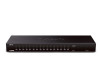
Front Panel Product Overview Figure 1- KVM-440 Front Panel AB C D Figure 2 - KVM-450 Front Panel AB C D Device Status LEDs and Buttons Item Feature A Status LEDs B Switch Button C Reset Switch D 3 Power LED Description Selected (Red): A Red LED indicates that the corresponding PC - D-Link KVM-450 | Quick Install Guide - Page 4
Rear Panel Figure 3 - KVM-440 Rear Panel AB C D Figure 4 - KVM-450 Rear Panel AB C D KVM Port Connections Item A Feature PS/2 Mouse Console Port Description Connects to the PS/2 mouse B PS/2 Keyboard Console Connects to the PS/2 keyboard Port C VGA Monitor Console Port Connects to the - D-Link KVM-450 | Quick Install Guide - Page 5
you to enable USB in BIOS to make the USB interface work. Console Connection: Plug the keyboard, mouse and monitor into the console ports on the rear panel of the KVM Switch. System Connection: Use the 4-in1 KVM combo cable to connect your computers. Refer to the figures and instructions shown below - D-Link KVM-450 | Quick Install Guide - Page 6
Note: Please contact your reseller to purchase additional 4-in-1 KVM combo cables. Figure 5: 4-in-1 KVM combo cable You can connect the KVM switch to computers using one of the three methods shown below: A. Connect USB, PS/2 Keyboard, PS/2 Mouse and VGA connectors to your computer. We recommend that - D-Link KVM-450 | Quick Install Guide - Page 7
B. Connect only PS/2 Keyboard, PS/2 Mouse and VGA connectors to your computer. (Figure 7) Figure 7: PS/2 and VGA Setup C. Connect only USB and VGA connectors to your computer. (Figure 8) Figure 8: USB and VGA Setup 7 - D-Link KVM-450 | Quick Install Guide - Page 8
chain, please follow the instruction below. A. Power off any attached computers/devices before installing the KVM Switch. B. Use the 4-in-1 KVM combo cable (See Figure 5) to connect one or more Slave KVM Switches to any PC port on the Master KVM Switch. The KVM to KVM must be connected through - D-Link KVM-450 | Quick Install Guide - Page 9
can select a computer to control with the KVM switch using the front panel buttons, hotkeys, or OSD. 1. Button Operation Press the front panel button to select the connected PC. 2. Hotkey Operation Please refer to the Hotkey Operation section in the User Manual. 3. OSD Operation Please refer to the - D-Link KVM-450 | Quick Install Guide - Page 10
Notes 10 - D-Link KVM-450 | Quick Install Guide - Page 11
Notes 11 - D-Link KVM-450 | Quick Install Guide - Page 12
Canada Telephone (877) 354-6560 World Wide Web http://support.dlink.ca Version 1.0 July 6, 2011 Copyright ©2011 D-Link Corporation/D-Link Systems, Inc. All rights reserved. D-Link, and the D-Link logo are registered trademarks of D-Link Corporation or its subsidiaries in the United States and other
-
 1
1 -
 2
2 -
 3
3 -
 4
4 -
 5
5 -
 6
6 -
 7
7 -
8
-
9
-
10
-
11
-
12
 |
 |
