Dacor ER36D Planning Guides
Dacor ER36D Manual
 |
View all Dacor ER36D manuals
Add to My Manuals
Save this manual to your list of manuals |
Dacor ER36D manual content summary:
- Dacor ER36D | Planning Guides - Page 1
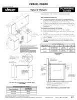
ER36D, ER48D Document # PG05-004 Epicure® Ranges Revised 05/14/10 Page 1/2 PLANNING GUIDE Product tolerances: +/- 1/16" (+/- 1.6 mm) unless otherwise stated 48" (1219 mm) 30 3/4" (781 mm) 29 3/8" (746 mm) 28 1/4" (718 mm) 26 1/8" (664 mm) (229 mm) Front of - Dacor ER36D | Planning Guides - Page 2
■■ The junction box and gas shut off valve must be located so that the range can be pulled out for service while the appliance remains connected. Range Model ER36D ER48D CUT-OUT DIMENSIONS F G 42" (1067 mm)* 36" (914 mm)** 36 1/16" (916 mm)** 54" (1372 mm)* 48" (1219 mm)** 48 1/16" (1221 mm
-
 1
1 -
 2
2
 |
 |
PLANNING
GUIDE
www.Dacor.com
Phone: (800) 793-0093
Specifications subject to change without notice.
Install all appliances according to accompanying installation instructions.
5.10
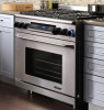
Epicure
®
Ranges
ER36D, ER48D
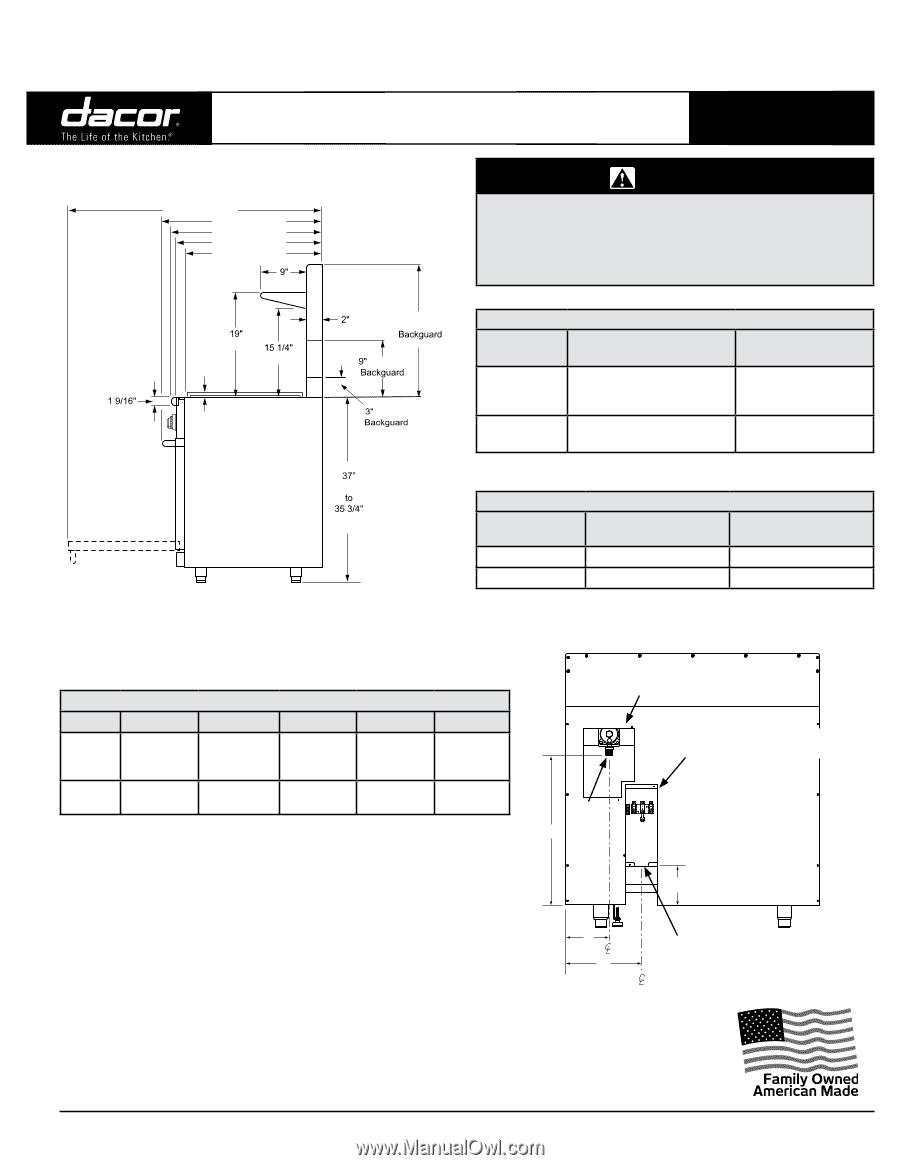
GAS - ELECTRICAL ACCESS DIMENSIONS
Model
A
B
C
D
E*
ER36D
5 5/8”
(142.9 mm)
18 3/8”
(466.7 mm)
10 3/4”
(273.0 mm)
13 11/16”
(347.7 mm)
7/8”
(22.2 mm)
ER48D
3 13/16”
(96.8 mm)
18 11/16”
(474.7 mm)
9 3/8”
(238.1 mm)
13 3/4”
(349.3 mm)
1 1/8”
(28.6 mm)
* The diameter on models equipped for use in Canada is ¼” (6.4mm) larger than
those stated. Canadian units come from the factory pre-wired with an appliance
cord. When installing an appliance cord on models that are not pre-wired, the hole
size must be increased to 1 1/8” (1 3/8” for model ER48D) by removing the conduit
bracket inside the range electrical access box.
48” (1219 mm)
Front of open door
Front of handle
Front edge of bull nose
Front panel
Rear of front panel/oven door
30 3/4” (781 mm)
(483 mm)
(908 mm)
(940 mm)
(76 mm)
24” (610 mm)
(51 mm)
(387 mm)
(40 mm)
(229 mm)
(229 mm)
29 3/8” (746 mm)
28 1/4” (718 mm)
26 1/8” (664 mm)
**
**
**
** Optional
1 1/16” (27 mm) to cooking
surface (top of grates) from
top of trim
Finished side
panel
Width:
ER36D - 35 7/8” (911 mm)
ER48D - 47 7/8” (1216 mm)
B
A
C
D
Gas regulator access,
cover removed
Range electrical access,
cover removed
E
Electrical connection
hole in bottom
Inlet
Back of range
Product tolerances: +/- 1/16” (+/- 1.6 mm) unless otherwise stated
GAS SUPPLY PRESSURE REQUIREMENTS*
Gas Type
Manifold Pressure
Minimum Gas Supply
Pressure
Natural Gas
5” Water Column
6” Water Column
Propane (LP)
10” Water Column
11” Water Column
* Maximum gas supply pressure 1/2 p.s.i. for all models
WARNING
Observe all governing codes and ordinances during planning
•
and installation. Contact your local building department for
further information.
This appliance must be installed in accordance with the
•
accompanying installation instructions.
ELECTRIC CIRCUIT REQUIREMENTS
Range Model
Circuit Required
Total Connected Load
ER36D
240 Vac, 4-wire* 60 Hz, 30
Amp. (Min.) 40 Amp.
(Recommended)
6.5 kW (28 Amp.)
ER48D
240 Vac, 4-wire* 60 Hz, 50
Amp.
10.0 kW (42 Amp.)
* 4-wire, two 120 Vac hot (L1 and L2), one neutral, one ground
Document # PG05-004
Revised 05/14/10
Page 1/2