Dacor ER36G Planning Guides
Dacor ER36G Manual
 |
View all Dacor ER36G manuals
Add to My Manuals
Save this manual to your list of manuals |
Dacor ER36G manual content summary:
- Dacor ER36G | Planning Guides - Page 1
Document # PG05-002 ER36G, ER36GI 36" Wide, Epicure® Gas Range Revised 05/25/10 Page 1/3 PLANNING GUIDE warning • Observe all governing codes and ordinances during planning and installation. Contact your local building department for further information. • This appliance must be installed in - Dacor ER36G | Planning Guides - Page 2
Document # PG05-002 B ER36G, ER36GI 36" Wide, Epicure® Gas Range Revised 05/25/10 Page 2/3 PLANNING GUIDE All tolerances +1/16" -0 (+1.6 mm, 0) unless otherwise noted. A * B C 36 1/16" (916 mm) 30" (762 mm) Minimum 36" (914 mm) Recommended 37 7/8" (962 mm) Maximum * See the - Dacor ER36G | Planning Guides - Page 3
-002 ER36G, ER36GI 36" Wide, Epicure® Gas Range Revised 05/25/10 Page 3/3 PLANNING GUIDE 12 1/2" (318 mm) 15" (381 mm) 15 7/8" (403 mm) to 18" (457 mm) 3 3/4" (95 mm) Back of Range CL 12" (305mm) 2 1/2" (64mm) 1" (25mm) 3 1/2" CL (89mm) Utility Clearance Behind Range Gas Type Natural LP
-
 1
1 -
 2
2 -
 3
3
 |
 |
PLANNING
GUIDE
www.Dacor.com
Phone: (800) 793-0093
Specifications subject to change without notice.
Install all appliances according to accompanying installation instructions.
5.4
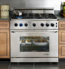
36” Wide, Epicure
®
Gas Range
ER36G, ER36GI
Document # PG05-002
Revised 05/25/10
Page 1/3
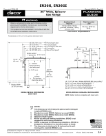
WARNING
Observe all governing codes and ordinances during
•
planning and installation. Contact your local building
department for further information.
This appliance must be installed in accordance with the
•
accompanying installation instructions.
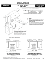
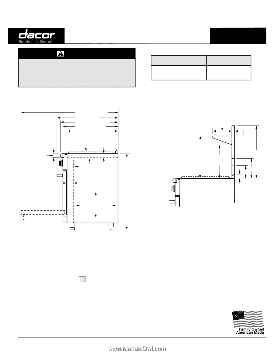
All tolerances ±1/16” (±1.6 mm) unless otherwise noted.
1 9/16”
(40 mm)
2” (51 mm)
1
3” (76 mm)
Front of open door
Front of handle
Front edge of bull nose
Front panel
Rear of front panel
7
26 3/4” (679 mm)
27 13/16” (706 mm)
29” (736 mm)
24 5/8” (625 mm)
ER36G:
Full stainless
steel side panels
ER36GI:
Partial stainless
steel side panel
Grates extend
1” above trim
Product Width:
35 7/8” (911 mm)
35 3/4”
(908 mm)
to
37 7/8”
(962 mm)
46 7/8” (1191 mm)
1 1/4”
(32 mm)
15 1/4”
(387 mm)
A
B
C
D
19”
(482 mm)
9”
(229 mm)
(A) 1 3/4” (44 mm): Model AER36GLBG (low profile)
2
(B) 6” (152 mm): Model AER36GBG6
3, 5
(C) 9” (229 mm): Model AER36GBG9
4, 5
(D) 24” (610 mm): Model AER36GBG24
4, 5
ER36G/ER36GI DIMENSIONS
SIDE VIEW
ER36G/ER36GI AVAILABLE BACKGUARDS
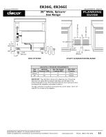
Electrical Circuit
Required
Total Connected
Load
120 Vac, 60 Hz, 15 Amp.
grounded, dedicated, 3 prong
electrical outlet
5.0 Amps. @120 Vac,
60 Hz,
ELECTRICAL REQUIREMENTS
NOTES:
Trim thickness is 1/4” (6 mm) with optional self-rimming kit
1.
installed (ER36GI only).
Standard on model ER36GI. Optional on model ER36G.
2.
Standard on model ER36G. Optional on model ER36GI.
3.
Optional on both models.
4.
Not for use with self rimming installations. ER36G is not
5.
equipped for self-rimming installation.
ER36G is designed for freestanding installations. ER36GI is
6.
designed for installation in a recessed cabinet or island.
This dimension is shortened to 24 inches when the self-
7.
rimming kit is installed (ER36GI only).
NOTE:
Neither model is compatible with raised vents.