Dell 5110 Color Laser Service Manual
Dell 5110 Color Laser Manual
 |
View all Dell 5110 Color Laser manuals
Add to My Manuals
Save this manual to your list of manuals |
Dell 5110 Color Laser manual content summary:
- Dell 5110 Color Laser | Service Manual - Page 1
Dell™ Inspiron™ N5110 Service Manual Regulatory model: P17F Regulatory type: P17F001 - Dell 5110 Color Laser | Service Manual - Page 2
CAUTION indicates potential damage to hardware or loss of data if instructions are not followed. WARNING: A WARNING indicates a potential for to either the entities claiming the marks and names or their products. Dell Inc. disclaims any proprietary interest in trademarks and trade names other than - Dell 5110 Color Laser | Service Manual - Page 3
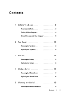
Contents 1 Before You Begin 9 Recommended Tools 9 Turning Off Your Computer 9 Before Working Inside Your Computer 10 2 Top Cover 13 Removing the Top Cover 13 Replacing the Top Cover 14 3 Battery 15 Removing the Battery 15 Replacing the Battery 16 4 Module Cover 17 Removing the Module - Dell 5110 Color Laser | Service Manual - Page 4
Replacing the Memory Module(s 20 6 Optical Drive 23 Removing the Optical Drive 23 Replacing the Optical Drive 24 7 Keyboard 27 Removing the Keyboard 27 Replacing the Keyboard 29 8 Palm-Rest Assembly 31 Removing the Palm-Rest Assembly 31 Replacing the Palm-Rest Assembly 34 9 Wireless Mini- - Dell 5110 Color Laser | Service Manual - Page 5
Removing the Display Bezel 44 Replacing the Display Bezel 45 Display Panel 46 Removing the Display Panel 46 Replacing the Display Panel 47 Display Cable 48 Removing the Display Cable 48 Replacing the Display Cable 49 Display-Panel Brackets 50 Removing the Display-Panel Brackets 50 - Dell 5110 Color Laser | Service Manual - Page 6
14 System Board 65 Removing the System Board 65 Replacing the System Board 66 Entering the Service Tag in the BIOS 68 15 Speakers 69 Removing the Speakers 69 Replacing the Speakers 70 16 Hard Drive 71 Removing the Hard Drive 71 Replacing - Dell 5110 Color Laser | Service Manual - Page 7
19 I/O Board 83 Removing the I/O Board 83 Replacing the I/O Board 84 20 VGA/Power Board 85 Removing the VGA/Power Board 85 Replacing the VGA/Power Board 86 21 Flashing the BIOS 89 Contents 7 - Dell 5110 Color Laser | Service Manual - Page 8
8 Contents - Dell 5110 Color Laser | Service Manual - Page 9
1 Before You Begin This manual provides procedures for removing and installing components in your -blade screwdriver • Phillips screwdriver • Plastic scribe • BIOS executable update program available at support.dell.com Turning Off Your Computer CAUTION: To avoid losing data, save and close all - Dell 5110 Color Laser | Service Manual - Page 10
a component such as a processor by its edges, not by its pins. CAUTION: Only a certified service technician should perform repairs on your computer. Damage due to servicing that is not authorized by Dell is not covered by your warranty. CAUTION: When you disconnect a cable, pull on its connector or - Dell 5110 Color Laser | Service Manual - Page 11
CAUTION: To help prevent damage to the system board, remove the main battery (see "Removing the Battery" on page 15) before working inside the computer. 7 Remove the battery (see "Removing the Battery" on page 15). 8 Turn the computer top-side up, open the display, and press the power button to - Dell 5110 Color Laser | Service Manual - Page 12
12 Before You Begin - Dell 5110 Color Laser | Service Manual - Page 13
dell.com/regulatory_compliance. CAUTION: Only a certified service technician should perform repairs on your computer. Damage due to servicing that is not authorized by Dell working inside the computer. Removing the Top Cover 1 Follow the instructions in "Before You Begin" on page 9. 2 Press and hold - Dell 5110 Color Laser | Service Manual - Page 14
1 2 1 top cover 2 release button Replacing the Top Cover 1 Follow the instructions in "Before You Begin" on page 9. NOTE: Ensure that the DELL logo is facing towards the back of the computer while replacing the top cover. 2 Align the top cover to the display back cover. 3 Slide the - Dell 5110 Color Laser | Service Manual - Page 15
dell.com/regulatory_compliance. CAUTION: Only a certified service technician should perform repairs on your computer. Damage due to servicing that is not authorized by Dell Dell computer. Do not use batteries designed for other Dell computers. Removing the Battery 1 Follow the instructions - Dell 5110 Color Laser | Service Manual - Page 16
3 2 1 1 battery release latch 3 battery lock latch 2 battery Replacing the Battery 1 Follow the instructions in "Before You Begin" on page 9. 2 Slide the battery into the battery bay until it clicks into place. 3 Slide the battery lock latch to the lock position. 16 Battery - Dell 5110 Color Laser | Service Manual - Page 17
dell.com/regulatory_compliance. CAUTION: Only a certified service technician should perform repairs on your computer. Damage due to servicing that is not authorized by Dell working inside the computer. Removing the Module Cover 1 Follow the instructions in "Before You Begin" on page 9. 2 Remove the - Dell 5110 Color Laser | Service Manual - Page 18
screw 2 module cover Replacing the Module Cover CAUTION: To avoid damage to the computer, use only the battery designed for this particular Dell computer. 1 Follow the instructions in "Before You Begin" on page 9. 2 Align the tabs on the module cover with the slots on the computer base and snap - Dell 5110 Color Laser | Service Manual - Page 19
dell.com/regulatory_compliance. CAUTION: Only a certified service technician should perform repairs on your computer. Damage due to servicing that is not authorized by Dell your Setup Guide for information on the type of memory supported by your computer. NOTE: Memory modules purchased from Dell are - Dell 5110 Color Laser | Service Manual - Page 20
two connectors, install a memory module in the connector labeled "DIMM A" before you install a memory module in the connector labeled "DIMM B." 1 Follow the instructions in "Before You Begin" on page 9. 2 Align the notch in the memory module with the tab in the memory-module connector. 3 Slide the - Dell 5110 Color Laser | Service Manual - Page 21
2 1 1 tab 2 notch 4 Replace the module cover (see "Replacing the Module Cover" on page 18). 5 Replace the battery (see "Replacing the Battery" on page 16), or connect the AC adapter to your computer and an electrical outlet. CAUTION: Before turning on the computer, replace all screws and ensure - Dell 5110 Color Laser | Service Manual - Page 22
22 Memory - Dell 5110 Color Laser | Service Manual - Page 23
dell.com/regulatory_compliance. CAUTION: Only a certified service technician should perform repairs on your computer. Damage due to servicing that is not authorized by Dell working inside the computer. Removing the Optical Drive 1 Follow the instructions in "Before You Begin" on page 9. 2 Remove the - Dell 5110 Color Laser | Service Manual - Page 24
2 1 1 optical-drive assembly 2 plastic scribe Replacing the Optical Drive 1 Follow the instructions in "Before You Begin" on page 9. 2 Slide the optical-drive assembly into the optical-drive bay until it is fully seated. 3 Replace the module cover ( - Dell 5110 Color Laser | Service Manual - Page 25
Optical Drive 25 - Dell 5110 Color Laser | Service Manual - Page 26
26 Optical Drive - Dell 5110 Color Laser | Service Manual - Page 27
dell.com/regulatory_compliance. CAUTION: Only a certified service technician should perform repairs on your computer. Damage due to servicing that is not authorized by Dell working inside the computer. Removing the Keyboard 1 Follow the instructions in "Before You Begin" on page 9. 2 Remove the - Dell 5110 Color Laser | Service Manual - Page 28
1 2 1 plastic scribe 2 keyboard CAUTION: The keycaps on the keyboard are fragile, easily dislodged, and time-consuming to replace. Be careful when removing and handling the keyboard. CAUTION: Be extremely careful when removing and handling the keyboard. Failure to do so could result in scratching - Dell 5110 Color Laser | Service Manual - Page 29
1 2 1 keyboard cable 2 keyboard-cable connector Replacing the Keyboard 1 Follow the instructions in "Before You Begin" on page 9. 2 Slide the keyboard cable into the connector on the system board and press down on the connector latch to - Dell 5110 Color Laser | Service Manual - Page 30
6 Replace the battery (see "Replacing the Battery" on page 16). 30 Keyboard - Dell 5110 Color Laser | Service Manual - Page 31
dell.com/regulatory_compliance. CAUTION: Only a certified service technician should perform repairs on your computer. Damage due to servicing that is not authorized by Dell inside the computer. Removing the Palm-Rest Assembly 1 Follow the instructions in "Before You Begin" on page 9. 2 Remove the - Dell 5110 Color Laser | Service Manual - Page 32
4 Turn the computer over and open the display as far as possible. 5 Remove the keyboard (see "Removing the Keyboard" on page 27). 6 Remove the four screws on the palm-rest assembly. CAUTION: Pull on the plastic tab on top of the connectors to avoid damaging the connectors. 7 Disconnect the power- - Dell 5110 Color Laser | Service Manual - Page 33
4 3 1 2 1 power-button board cable 3 screws (4) 2 touch-pad cable 4 hot-key board cable CAUTION: Carefully separate the palm rest from the computer base to avoid damage to the palm rest. 8 Using a plastic scribe, carefully pry out the palm-rest assembly along the rear edge and then ease the palm - Dell 5110 Color Laser | Service Manual - Page 34
1 2 1 plastic scribe 2 palm-rest assembly Replacing the Palm-Rest Assembly 1 Follow the instructions in "Before You Begin" on page 9. 2 Align the tabs on the palm rest assembly with the slots on the computer base and gently snap the - Dell 5110 Color Laser | Service Manual - Page 35
6 Close the display and turn the computer over. 7 Replace the six screws that secure the palm-rest assembly to the computer base. 8 Replace the battery (see "Replacing the Battery" on page 16). CAUTION: Before turning on the computer, replace all screws and ensure that no stray screws remain inside - Dell 5110 Color Laser | Service Manual - Page 36
36 Palm-Rest Assembly - Dell 5110 Color Laser | Service Manual - Page 37
dell.com/regulatory_compliance. CAUTION: Only a certified service technician should perform repairs on your computer. Damage due to servicing that is not authorized by Dell Dell does not guarantee compatibility or provide support for Mini-Cards from sources other than Dell Follow the instructions in " - Dell 5110 Color Laser | Service Manual - Page 38
-Card to the system board. d Lift the Mini-Card out of the system-board connector. 4 If you are removing the WLAN Mini-Card: a Follow the instructions from step 3 to step 9 in "Removing the Palm-Rest Assembly" on page 31. b Disconnect the antenna cables from the Mini-Card. c Remove the screw that - Dell 5110 Color Laser | Service Manual - Page 39
Replacing the Mini-Card(s) 1 Follow the instructions in "Before You Begin" on page 9. 2 Remove the The following table provides the antenna cable color scheme for the Mini-Cards supported by your computer. Connectors on the Mini-Card Antenna Cable Color Scheme WLAN (2 antenna cables) Main WLAN - Dell 5110 Color Laser | Service Manual - Page 40
Follow the instructions from step 4 to step 8 in "Replacing the Palm-Rest Assembly" on page 34. 8 Replace . Failure to do so may result in damage to the computer. 9 Install the drivers and utilities for your computer, as required. NOTE: If you are installing a communication card from a source other - Dell 5110 Color Laser | Service Manual - Page 41
dell.com/regulatory_compliance. CAUTION: Only a certified service technician should perform repairs on your computer. Damage due to servicing that is not authorized by Dell computer. Display Assembly Removing the Display Assembly 1 Follow the instructions in "Before You Begin" on page 9. 2 Remove the - Dell 5110 Color Laser | Service Manual - Page 42
4 Follow the instructions from step 3 to step 9 in "Removing the Palm-Rest Assembly" page 37). 7 Note the routing of the Mini-Card antenna cables and remove the cables from the routing guides. 8 Remove the four screws that secure the display assembly to the computer base. 9 Lift the display assembly - Dell 5110 Color Laser | Service Manual - Page 43
(4) 4 Mini-Card antenna cables (2) Replacing the Display Assembly 1 Follow the instructions in "Before You Begin" on page 9. 2 Place the display assembly in . 3 Route the Mini-Card antenna cables through the routing guides. 4 Connect the Mini-Card antenna cables to the Mini-Card(s) (see " - Dell 5110 Color Laser | Service Manual - Page 44
screws remain inside the computer. Failure to do so may result in damage to the computer. Display Bezel Removing the Display Bezel 1 Follow the instructions in "Before You Begin" on page 9. 2 Remove the top cover (see "Removing the Top Cover" on page 13). 3 Remove the display assembly (see "Removing - Dell 5110 Color Laser | Service Manual - Page 45
1 1 display bezel Replacing the Display Bezel 1 Follow the instructions in "Before You Begin" on page 9. 2 Realign the display bezel over the display panel and gently snap it into place. 3 Replace the display assembly (see " - Dell 5110 Color Laser | Service Manual - Page 46
Display Panel Removing the Display Panel 1 Follow the instructions in "Before You Begin" on page 9. 2 Remove the display assembly (see "Removing the Display Assembly" on page 41). 3 Remove the display bezel (see "Removing the - Dell 5110 Color Laser | Service Manual - Page 47
display cable and Mini-Card antenna cables routing and remove them from the routing guides on the display back cover. 8 Turn the display panel over and place Brackets" on page 50). Replacing the Display Panel 1 Follow the instructions in "Before You Begin" on page 9. 2 Replace the display-panel - Dell 5110 Color Laser | Service Manual - Page 48
remain inside the computer. Failure to do so may result in damage to the computer. Display Cable Removing the Display Cable 1 Follow the instructions in "Before You Begin" on page 9. 2 Remove the display assembly (see "Removing the Display Assembly" on page 41). 3 Remove the display bezel (see - Dell 5110 Color Laser | Service Manual - Page 49
1 2 1 display cable 2 tape Replacing the Display Cable 1 Follow the instructions in "Before You Begin" on page 9. 2 Connect the display cable to the display-board connector and secure it with the tape. 3 Replace the display panel ( - Dell 5110 Color Laser | Service Manual - Page 50
Display-Panel Brackets Removing the Display-Panel Brackets 1 Follow the instructions in "Before You Begin" on page 9. 2 Remove the display assembly (see "Removing the Display Assembly" on page 41). 3 Remove the display bezel (see "Removing the - Dell 5110 Color Laser | Service Manual - Page 51
2 Align the screw holes on the display-panel bracket with the screw holes on the display panel and replace the four screws (two on each side). 3 Replace the display panel (see "Replacing the Display Panel" on page 47). 4 Replace the display bezel (see "Replacing the Display Bezel" on page 45). 5 - Dell 5110 Color Laser | Service Manual - Page 52
52 Display - Dell 5110 Color Laser | Service Manual - Page 53
dell.com/regulatory_compliance. CAUTION: Only a certified service technician should perform repairs on your computer. Damage due to servicing that is not authorized by Dell working inside the computer. Removing the Hinge Cover 1 Follow the instructions in "Before You Begin" on page 9. 2 Remove the - Dell 5110 Color Laser | Service Manual - Page 54
2 1 1 screws (4) 2 tabs (7) 6 Lift the hinge cover off the computer base. 1 54 Hinge Cover - Dell 5110 Color Laser | Service Manual - Page 55
1 Hinge Cover Replacing the Hinge Cover 1 Follow the instructions in "Before You Begin" on page 9. 2 Align the seven tabs on the hinge cover with the slots on the computer base and snap the hinge - Dell 5110 Color Laser | Service Manual - Page 56
56 Hinge Cover - Dell 5110 Color Laser | Service Manual - Page 57
dell.com/regulatory_compliance. CAUTION: Only a certified service technician should perform repairs on your computer. Damage due to servicing that is not authorized by Dell inside the computer. Removing the Camera Module 1 Follow the instructions in "Before You Begin" on page 9. 2 Remove the battery ( - Dell 5110 Color Laser | Service Manual - Page 58
bezel (see "Replacing the Display Bezel" on page 45). 5 Replace the display assembly (see "Replacing the Display Assembly" on page 43). 6 Follow the instructions from step 2 to step 7 in "Replacing the Palm-Rest Assembly" on page 34. 7 Replace the battery (see "Replacing the Battery" on page 16 - Dell 5110 Color Laser | Service Manual - Page 59
Camera Module 59 - Dell 5110 Color Laser | Service Manual - Page 60
60 Camera Module - Dell 5110 Color Laser | Service Manual - Page 61
dell.com/regulatory_compliance. CAUTION: Only a certified service technician should perform repairs on your computer. Damage due to servicing that is not authorized by Dell the computer. Removing the Coin-Cell Battery 1 Follow the instructions in "Before You Begin" on page 9. 2 Remove the battery (see - Dell 5110 Color Laser | Service Manual - Page 62
"Before You Begin" on page 9. 2 With the positive side up, snap the coin-cell battery into the battery socket on the system board. 3 Follow the instructions from step 2 to step 7 in "Replacing the Palm-Rest Assembly" on page 34. 4 Replace the battery (see "Replacing the Battery" on page 16). 62 - Dell 5110 Color Laser | Service Manual - Page 63
CAUTION: Before turning on the computer, replace all screws and ensure that no stray screws remain inside the computer. Failure to do so may result in damage to the computer. Coin-Cell Battery 63 - Dell 5110 Color Laser | Service Manual - Page 64
64 Coin-Cell Battery - Dell 5110 Color Laser | Service Manual - Page 65
dell.com/regulatory_compliance. CAUTION: Only a certified service technician should perform repairs on your computer. Damage due to servicing that is not authorized by Dell (see "Removing the Module Cover" on page 17). 5 Follow the instructions from step 4 to step 5 in "Removing the Optical Drive" on - Dell 5110 Color Laser | Service Manual - Page 66
to disconnect the connector on the system board from the connector on the I/O board. 13 Turn the system board assembly over. 14 Follow the instructions from step 3 to step 5 in "Removing the Hard Drive" on page 71. 15 Remove the thermal cooling assembly (see "Removing the Thermal-Cooling Assembly - Dell 5110 Color Laser | Service Manual - Page 67
11 Replace the display assembly (see "Replacing the Display Assembly" on page 43). 12 Follow the instructions from step 2 to step 7 in "Replacing the Palm-Rest Assembly" on page 34. 13 the system board, enter the computer Service Tag in the BIOS of the replacement system board. System Board 67 - Dell 5110 Color Laser | Service Manual - Page 68
18 Enter the service tag (see "Entering the Service Tag in the BIOS" on page 68). Entering the Service Tag in the BIOS 1 Ensure that the AC adapter is plugged in and that the main battery is installed properly. 2 Turn on the computer. 3 Press - Dell 5110 Color Laser | Service Manual - Page 69
Damage due to servicing that is not authorized by Dell is not covered by your warranty. CAUTION: To help prevent damage to the system board, remove the main battery (see "Removing the Battery" on page 15) before working inside the computer. Removing the Speakers 1 Follow the instructions in "Before - Dell 5110 Color Laser | Service Manual - Page 70
in "Before You Begin" on page 9. 2 Place the speakers on the computer base and route the speaker cable through the routing guides. 3 Follow the instructions from step 2 to step 17 in "Replacing the System Board" on page 67. CAUTION: Before turning on the computer, replace all screws and ensure - Dell 5110 Color Laser | Service Manual - Page 71
compatibility or provide support for hard drives from sources other than Dell. NOTE: If you are installing a hard drive from a source other than Dell, you need to install an operating system, drivers, and utilities on the new hard drive. Removing the Hard Drive 1 Follow the instructions in "Before - Dell 5110 Color Laser | Service Manual - Page 72
4 Slide the hard-drive assembly to disconnect it from the system-board connector. 5 Lift the hard-drive assembly off the system board. 2 1 1 hard-drive assembly 2 screws (2) 6 Remove the four screws that secure the hard drive to the hard-drive bracket. 7 Lift the hard drive away from the hard- - Dell 5110 Color Laser | Service Manual - Page 73
1 screws (4) 2 hard-drive bracket Replacing the Hard Drive 1 Follow the instructions in "Before You Begin" on page 9. 2 Remove the new hard drive hard-drive assembly to the system-board. 8 Follow the instructions from step 6 to step 16 in "Replacing the System Board" on page 67. Hard Drive 73 - Dell 5110 Color Laser | Service Manual - Page 74
CAUTION: Before turning on the computer, replace all screws and ensure that no stray screws remain inside the computer. Failure to do so may result in damage to the computer. 74 Hard Drive - Dell 5110 Color Laser | Service Manual - Page 75
dell.com/regulatory_compliance. CAUTION: Only a certified service technician should perform repairs on your computer. Damage due to servicing that is not authorized by Dell computer. Removing the Thermal-Cooling Assembly 1 Follow the instructions in "Before You Begin" on page 9. 2 Remove the battery ( - Dell 5110 Color Laser | Service Manual - Page 76
. 4 Connect the fan cable to the connector on the system board. 5 Adhere the tape that secures the fan cable to the system board 6 Follow the instructions from step 4 to step 13 in "Replacing the System Board" on page 67. 7 Replace the battery (see "Replacing the Battery" on page 16). 76 Thermal - Dell 5110 Color Laser | Service Manual - Page 77
CAUTION: Before turning on the computer, replace all screws and ensure that no stray screws remain inside the computer. Failure to do so may result in damage to the computer. Thermal-Cooling Assembly 77 - Dell 5110 Color Laser | Service Manual - Page 78
78 Thermal-Cooling Assembly - Dell 5110 Color Laser | Service Manual - Page 79
dell.com/regulatory_compliance. CAUTION: Only a certified service technician should perform repairs on your computer. Damage due to servicing that is not authorized by Dell the Processor Module 1 Follow the instructions in "Before You Begin" on page 9. 2 Follow the instructions from step 2 to step 15 - Dell 5110 Color Laser | Service Manual - Page 80
4 1 2 3 1 ZIF socket 3 pin-1 corner 2 processor module 4 ZIF-socket cam screw Replacing the Processor Module 1 Follow the instructions in "Before You Begin" on page 9. NOTE: If a new processor is installed, you will receive a new thermal-cooling assembly, which will include an affixed thermal - Dell 5110 Color Laser | Service Manual - Page 81
turning the cam screw. 3 Tighten the ZIF socket by turning the cam screw clockwise to secure the processor module to the system board. 4 Follow the instructions from step 3 to step 16 in "Replacing the System Board" on page 67. CAUTION: Before turning on the computer, replace all screws and ensure - Dell 5110 Color Laser | Service Manual - Page 82
82 Processor Module - Dell 5110 Color Laser | Service Manual - Page 83
a certified service technician should perform repairs on your computer. Damage due to servicing that is not authorized by Dell is not the display assembly (see "Removing the Display Assembly" on page 41). 3 Follow the instructions from step 2 to step 12 in "Removing the System Board" on page 65. 4 - Dell 5110 Color Laser | Service Manual - Page 84
-Card(s) (see "Replacing the Mini-Card(s)" on page 39). 4 Replace the hinge cover (see "Replacing the Hinge Cover" on page 55). 5 Follow the instructions from step 6 to step 16 in "Replacing the System Board" on page 67. 6 Replace the display assembly (see "Replacing the Display Assembly" on page 43 - Dell 5110 Color Laser | Service Manual - Page 85
dell.com/regulatory_compliance. CAUTION: Only a certified service technician should perform repairs on your computer. Damage due to servicing that is not authorized by Dell inside the computer. Removing the VGA/Power Board 1 Follow the instructions in "Before You Begin" on page 9. 2 Remove the display - Dell 5110 Color Laser | Service Manual - Page 86
on the base cover and place it on the base cover. 3 Replace the hinge cover (see "Replacing the Hinge Cover" on page 55). 4 Follow the instructions from step 6 to step 17 in "Replacing the System Board" on page 67. 5 Replace the display assembly (see "Replacing the Display Assembly" on page 43 - Dell 5110 Color Laser | Service Manual - Page 87
VGA/Power Board 87 - Dell 5110 Color Laser | Service Manual - Page 88
88 VGA/Power Board - Dell 5110 Color Laser | Service Manual - Page 89
is available or when replacing the system board. To flash the BIOS: 1 Turn on the computer. 2 Go to support.dell.com/support/downloads. 3 Locate the BIOS update file for your computer: NOTE: The Service Tag for your computer is located on a label at the bottom of your computer. If you have your - Dell 5110 Color Laser | Service Manual - Page 90
8 Double-click the file icon on the desktop and follow the instructions on the screen. 90 Flashing the BIOS
-
 1
1 -
 2
2 -
 3
3 -
 4
4 -
 5
5 -
 6
6 -
 7
7 -
8
-
9
-
10
-
11
-
12
-
13
-
14
-
15
-
16
-
17
-
18
-
19
-
20
-
21
-
22
-
23
-
24
-
25
-
26
-
27
-
28
-
29
-
30
-
31
-
32
-
33
-
34
-
35
-
36
-
37
-
38
-
39
-
40
-
41
-
42
-
43
-
44
-
45
-
46
-
47
-
48
-
49
-
50
-
51
-
52
-
53
-
54
-
55
-
56
-
57
-
58
-
59
-
60
-
61
-
62
-
63
-
64
-
65
-
66
-
67
-
68
-
69
-
70
-
71
-
72
-
73
-
74
-
75
-
76
-
77
-
78
-
79
-
80
-
81
-
82
-
83
-
84
-
85
-
86
-
87
-
88
-
89
-
90
 |
 |

Dell™ Inspiron™ N5110
Service Manual
Regulatory model: P17F
Regulatory type: P17F001