Dell Inspiron 13 N3010 Service Manual
Dell Inspiron 13 Manual
 |
View all Dell Inspiron 13 manuals
Add to My Manuals
Save this manual to your list of manuals |
Dell Inspiron 13 manual content summary:
- Dell Inspiron 13 | N3010 Service Manual - Page 1
Dell™ Inspiron™ N3010 Service Manual or loss of data if instructions are not followed. WARNING: without notice. © 2010 Dell Inc. All rights reserved. Dell Inc. is strictly forbidden. Trademarks used in this text: Dell and the DELL logo are trademarks of Dell Dell Inc. disclaims any proprietary interest in - Dell Inspiron 13 | N3010 Service Manual - Page 2
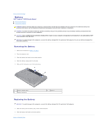
Back to Contents Page Battery Dell™ Inspiron™ N3010 Service Manual Removing the Battery Replacing the Battery WARNING: Before working inside your computer, read the safety information that shipped with your computer. For additional safety best - Dell Inspiron 13 | N3010 Service Manual - Page 3
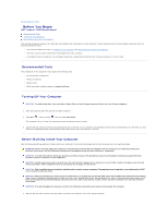
Dell™ Inspiron™ N3010 Service Manual Recommended Tools Turning Off Your Computer Before Working Inside Your Computer This manual provides l Phillips screwdriver l Plastic scribe l BIOS executable update program at support.dell.com Turning Off Your Computer CAUTION: To avoid losing data, save and - Dell Inspiron 13 | N3010 Service Manual - Page 4
2. Turn off your computer (see Turning Off Your Computer). CAUTION: To disconnect a network cable, first unplug the cable from your computer and then unplug the cable from the network device. 3. Disconnect all telephone or network cables from the computer. 4. Press and eject any installed cards from - Dell Inspiron 13 | N3010 Service Manual - Page 5
Flashing the BIOS Dell™ Inspiron™ N3010 Service Manual 1. Turn on the computer. 2. Go to support.dell.com/support/downloads. 3. Locate the BIOS update file for your computer: NOTE: The Service Tag for your the file icon on the desktop and follow the instructions on the screen. Back to Contents Page - Dell Inspiron 13 | N3010 Service Manual - Page 6
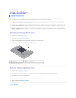
to Contents Page Memory-Module Cover Dell™ Inspiron™ N3010 Service Manual Removing the Memory-Module Cover Replacing module cover 3 memory-module cover tabs (3) Replacing the Memory-Module Cover 1. Follow the instructions in Before You Begin. 2. Align the tabs on the memory-module cover with the - Dell Inspiron 13 | N3010 Service Manual - Page 7
Internal Module With Bluetooth® Wireless Technology Dell™ Inspiron™ N3010 Service Manual Removing the Bluetooth Module Replacing the Bluetooth 1 screw 2 Bluetooth module Replacing the Bluetooth Module 1. Follow the instructions in Before You Begin 2. Align the connector on the Bluetooth module - Dell Inspiron 13 | N3010 Service Manual - Page 8
3. Replace the screw that secures the Bluetooth module to the system board. 4. Replace the palm rest assembly (see Replacing the Palm Rest Assembly). 5. Replace the keyboard (see Replacing the Keyboard). 6. Replace the memory module(s) (see Replacing the Memory Module(s)). 7. Replace the memory- - Dell Inspiron 13 | N3010 Service Manual - Page 9
Back to Contents Page Camera Module Dell™ Inspiron™ N3010 Service Manual Removing the Camera Module Replacing the Camera Module WARNING: Before working inside your computer, read the safety information that shipped with your computer. For additional - Dell Inspiron 13 | N3010 Service Manual - Page 10
13. Lift the camera module off the display cover. Replacing the Camera Module 1. Follow the instructions in Before You Begin. 2. Connect the display cable to the connector on the camera module. 3. Replace the tape that secures the display cable to the - Dell Inspiron 13 | N3010 Service Manual - Page 11
to Contents Page Coin-Cell Battery Dell™ Inspiron™ N3010 Service Manual Removing the Coin-Cell Battery Replacing , snap the coin-cell battery into the battery socket on the system board. 3. Follow the instructions from step 7 to step 21 in Replacing the System Board. CAUTION: Before turning on the - Dell Inspiron 13 | N3010 Service Manual - Page 12
Back to Contents Page Processor Module Dell™ Inspiron™ N3010 Service Manual Removing the Processor Module Replacing the Processor Module WARNING: Before working inside your computer, read the safety information that shipped with your computer. For additional - Dell Inspiron 13 | N3010 Service Manual - Page 13
clockwise to secure the processor module to the system board. 4. Replace the processor heat sink (see Replacing the Processor Heat Sink). 5. Follow the instructions from step 7 to step 21 in Replacing the System Board. CAUTION: Before turning on the computer, replace all screws and ensure that no - Dell Inspiron 13 | N3010 Service Manual - Page 14
Back to Contents Page Processor Heat Sink Fan Dell™ Inspiron™ N3010 Service Manual Removing the Processor Heat Sink Fan Replacing the Processor Heat Sink Fan WARNING: Before working inside your computer, read the safety information that shipped with - Dell Inspiron 13 | N3010 Service Manual - Page 15
NOTE: This procedure assumes that you have already removed the processor heat sink fan and are ready to replace it. 1. Follow the instructions in Before You Begin. 2. Place the processor heat sink fan in position and replace the screw that secures the processor heat sink fan to the - Dell Inspiron 13 | N3010 Service Manual - Page 16
to Contents Page Processor Heat Sink Dell™ Inspiron™ N3010 Service Manual Removing the Processor Heat Sink Replacing pad provided in the kit to ensure that thermal conductivity is achieved. 1. Follow the instructions in Before You Begin. 2. Place the processor heat sink in position. 3. In - Dell Inspiron 13 | N3010 Service Manual - Page 17
CAUTION: Before turning on the computer, replace all screws and ensure that no stray screws remain inside the computer. Failure to do so may result in damage to the computer. Back to Contents Page - Dell Inspiron 13 | N3010 Service Manual - Page 18
Back to Contents Page Display Dell™ Inspiron™ N3010 Service Manual Display Assembly Display Bezel Display Panel Display Panel Bracket Display Cable Display Hinges WARNING: Before working inside your computer, read the safety information that shipped - Dell Inspiron 13 | N3010 Service Manual - Page 19
(4) 2 display cable grounding screw 4 display assembly 12. Lift the display assembly off the computer. Replacing the Display Assembly 1. Follow the instructions in Before You Begin. 2. Place the display assembly in position. 3. In sequential order (indicated on the display hinge), replace the - Dell Inspiron 13 | N3010 Service Manual - Page 20
fingertips, carefully pry up the inside edge of the display bezel to remove it from the display assembly. Replacing the Display Bezel 1. Follow the instructions in Before You Begin. 2. Align the display bezel over the display panel, and gently snap it into place. 3. Replace the display assembly (see - Dell Inspiron 13 | N3010 Service Manual - Page 21
computer. Failure to do so may result in damage to the computer. Display Panel Bracket Removing the Display Panel Bracket 1. Follow the instructions in Before You Begin. 2. Remove the display assembly (see Removing the Display Assembly). 3. Remove the display bezel (see Removing the Display Bezel - Dell Inspiron 13 | N3010 Service Manual - Page 22
remain inside the computer. Failure to do so may result in damage to the computer. Display Cable Removing the Display Cable 1. Follow the instructions in Before You Begin. 2. Remove the display assembly (see Removing the Display Assembly). 3. Remove the display bezel (see Removing the Display Bezel - Dell Inspiron 13 | N3010 Service Manual - Page 23
inside the computer. Failure to do so may result in damage to the computer. Display Hinges Removing the Display Hinges 1. Follow the instructions in Before You Begin. 2. Remove the display assembly (see Removing the Display Assembly). 3. Remove the display bezel (see Removing the Display Bezel - Dell Inspiron 13 | N3010 Service Manual - Page 24
hinges to the display cover. 1 screws (2) 2 display hinges (2) 7. Lift the display hinges off the display cover. Replacing the Display Hinges 1. Follow the instructions in Before You Begin. 2. Place the display hinges in position and replace the two screws (one on each display hinge) that secure - Dell Inspiron 13 | N3010 Service Manual - Page 25
Dell™ Inspiron™ N3010 Service Manual support for hard drives from sources other than Dell. NOTE: If you are installing a hard drive from a source other than Dell, you need to install an operating system, drivers, and utilities on the new hard drive. Removing the Hard Drive 1. Follow the instructions - Dell Inspiron 13 | N3010 Service Manual - Page 26
to the system board. 8. Turn over the system board assembly. 9. Follow the instruction from step 7 to step 21 in Replacing the System Board. CAUTION: Before turning on Operating System" in the Setup Guide. 11. Install the drivers and utilities for your computer, as needed. Back to Contents Page - Dell Inspiron 13 | N3010 Service Manual - Page 27
Back to Contents Page Middle Cover Dell™ Inspiron™ N3010 Service Manual Removing the Middle Cover Replacing the Middle Cover WARNING: Before working inside your computer, read the safety information that shipped with your computer. For additional - Dell Inspiron 13 | N3010 Service Manual - Page 28
2. Align the tabs on the middle cover with the slots on the computer base and snap the middle cover into place. 3. Turn over the computer and replace the four screws that secure the middle cover to the computer base. 4. Replace the display assembly (see Replacing the Display Assembly). 5. Replace - Dell Inspiron 13 | N3010 Service Manual - Page 29
Dell™ Inspiron™ N3010 Service Manual servicing that is not authorized by Dell™ is not covered by your warranty. CAUTION: To help prevent damage to the system board, remove the main battery (see Removing the Battery) before working inside the computer. Removing the Keyboard 1. Follow the instructions - Dell Inspiron 13 | N3010 Service Manual - Page 30
on the system board. 1 keyboard cable 3 tabs (5) 2 connector latch 12. Lift the keyboard off the palm rest assembly. Replacing the Keyboard 1. Follow the instructions in Before You Begin. 2. Slide the keyboard cable into the connector on the system board and press down on the connector latch to - Dell Inspiron 13 | N3010 Service Manual - Page 31
CAUTION: Before turning on the computer, replace all screws and ensure that no stray screws remain inside the computer. Failure to do so may result in damage to the computer. Back to Contents Page - Dell Inspiron 13 | N3010 Service Manual - Page 32
Memory Module(s) Dell™ Inspiron™ N3010 Service Manual Removing the Guide for information on the type of memory supported by your computer. NOTE: Memory modules purchased from Dell -module connector. Replacing the Memory Module(s) 1. Follow the instructions in Before You Begin. NOTE: If you need to - Dell Inspiron 13 | N3010 Service Manual - Page 33
2. Align the notch in the memory module with the tab in the memory- module connector. 3. Slide the memory module firmly into the connector at a 45-degree angle, and press the memory module down until it clicks into place. If you do not hear the click, remove the memory module and reinstall it. NOTE: - Dell Inspiron 13 | N3010 Service Manual - Page 34
-Card Dell™ Inspiron™ N3010 Service Manual Removing supports one Mini-Card slot: l One half Mini-Card slot - for WLAN NOTE: Depending on the configuration of the computer when it was sold, the Mini-Card slot may or may not have a Mini-Card installed. Removing the Mini-Card 1. Follow the instructions - Dell Inspiron 13 | N3010 Service Manual - Page 35
the Mini-Card 1. Follow the instructions in Before You Begin. 2. Turn the system board over. 6. Follow the instructions from step 7 to step 21 in Replacing the scheme for the Mini- Card supported by your computer. Connectors on 8. Install the drivers and utilities for your computer, as required. - Dell Inspiron 13 | N3010 Service Manual - Page 36
Back to Contents Page Palm Rest Assembly Dell™ Inspiron™ N3010 Service Manual Removing the Palm Rest Assembly Replacing the Palm Rest Assembly WARNING: Before working inside your computer, read the safety information that shipped with your computer. - Dell Inspiron 13 | N3010 Service Manual - Page 37
routing of the Mini-Card antenna cables and remove them from the routing guides on the palm rest assembly. 12. Using a plastic scribe carefully pry palm rest assembly. 13. Lift the palm rest assembly off the computer base. Replacing the Palm Rest Assembly 1. Follow the instructions in Before You - Dell Inspiron 13 | N3010 Service Manual - Page 38
7. Replace the keyboard (see Replacing the Keyboard). 8. Turn the computer over and replace the seven screws that secure the palm rest assembly to the computer base. 9. Connect the antenna cables to the connectors on the Mini-card. 10. Replace the memory module(s) (see Replacing the Memory Module - Dell Inspiron 13 | N3010 Service Manual - Page 39
to Contents Page Power Button Board Dell™ Inspiron™ N3010 Service Manual Removing the Power Button Board Replacing button board off the palm rest assembly. Replacing the Power Button Board 1. Follow the instructions in Before You Begin. 2. Place the power button board on the palm rest assembly and - Dell Inspiron 13 | N3010 Service Manual - Page 40
5. Replace the keyboard (see Replacing the Keyboard). 6. Replace the memory module(s) (see Replacing the Memory Module(s)). 7. Replace the memory-module cover (see Replacing the Memory-Module Cover). 8. Replace the battery (see Replacing the Battery). CAUTION: Before turning on the computer, replace - Dell Inspiron 13 | N3010 Service Manual - Page 41
Back to Contents Page Speakers Dell™ Inspiron™ N3010 Service Manual Removing the Speakers Replacing the Speakers the speaker cables in the routing guides. 3. Replace the four screws (two on each speaker) that secure the speakers to the computer base. 4. Follow the instructions from step 7 to step 21 - Dell Inspiron 13 | N3010 Service Manual - Page 42
- Dell Inspiron 13 | N3010 Service Manual - Page 43
Dell™ Inspiron™ N3010 Service Manual Removing the System Board Replacing the System Board Entering the Service and contacts. Removing the System Board 1. Follow the instructions in Before You Begin. 2. Remove any installed card 13. Disconnect the speaker cable from the connector on the system board. - Dell Inspiron 13 | N3010 Service Manual - Page 44
Remove the Mini-Card (see Removing the Mini-Card). Replacing the System Board 1. Follow the instructions in Before You Begin. 2. Replace the Mini-Card (see Replacing the Mini-Card). 3. see Replacing the Processor Heat Sink Fan). 13. Replace the display assembly (see Replacing the Display Assembly). - Dell Inspiron 13 | N3010 Service Manual - Page 45
on the computer. NOTE: After you have replaced the system board, enter the computer Service Tag in the BIOS of the replacement system board. 22. Enter the service tag (see Entering the Service Tag in the BIOS). Entering the Service Tag in the BIOS 1. Ensure that the AC adapter is plugged in and that - Dell Inspiron 13 | N3010 Service Manual - Page 46
Back to Contents Page Dell™ Inspiron™ N3010 Service Manual NOTE: A NOTE indicates important information that helps you make better use of your computer. CAUTION: A CAUTION indicates potential damage to hardware or loss of data if instructions are not followed. WARNING: A WARNING indicates a - Dell Inspiron 13 | N3010 Service Manual - Page 47
Back to Contents Page VGA Connector Board Dell™ Inspiron™ N3010 Service Manual Removing the VGA Connector Board Replacing the VGA Connector Board WARNING: Before working inside your computer, read the safety information that shipped with your computer. - Dell Inspiron 13 | N3010 Service Manual - Page 48
2. Place the VGA connector board on the computer base and replace the two screws that secure the VGA connector board to the computer base. 3. Slide the VGA connector cable into the connector on the system board and press down on the connector latch to secure the cable. 4. Replace the middle cover (
-
 1
1 -
 2
2 -
 3
3 -
 4
4 -
 5
5 -
 6
6 -
 7
7 -
8
-
9
-
10
-
11
-
12
-
13
-
14
-
15
-
16
-
17
-
18
-
19
-
20
-
21
-
22
-
23
-
24
-
25
-
26
-
27
-
28
-
29
-
30
-
31
-
32
-
33
-
34
-
35
-
36
-
37
-
38
-
39
-
40
-
41
-
42
-
43
-
44
-
45
-
46
-
47
-
48
 |
 |

Dell™ Inspiron™ N3010 Service Manual
Notes, Cautions, and Warnings
Information in this document is subject to change without notice.
© 2010 Dell Inc. All rights reserved.
Reproduction of these materials in any manner whatsoever without the written permission of Dell Inc. is strictly forbidden.
Trademarks used in this text:
Dell
and the
DELL
logo are trademarks of Dell Inc.;
Bluetooth
is a registered trademark owned by Bluetooth SIG, Inc. and is used by Dell under
license;
Microsoft
and
Windows
are either trademarks or registered trademarks of Microsoft Corporation in the United States and/or other countries.
Other trademarks and trade names may be used in this document to refer to either the entities claiming the marks and names or their products. Dell Inc. disclaims any
proprietary interest in trademarks and trade names other than its own.
Regulatory model: P10S series
Regulatory type: P10S001
March 2010 Rev. A00
Before You Begin
Battery
Memory
-
Module Cover
Memory Module(s)
Keyboard
Palm Rest Assembly
Power Button Board
Internal Module With Bluetooth
®
Wireless Technology
Display
Camera Module
Processor Heat Sink Fan
Middle Cover
VGA Connector Board
System Board
Hard Drive
Processor Heat Sink
Processor Module
Wireless Mini
-
Card
Coin
-
Cell Battery
Speakers
Flashing the BIOS
NOTE:
A NOTE indicates important information that helps you make better use of your computer.
CAUTION:
A CAUTION indicates potential damage to hardware or loss of data if instructions are not followed.
WARNING:
A WARNING indicates a potential for property damage, personal injury, or death.