Dell Inspiron 24 3452 Service Manual
Dell Inspiron 24 3452 Manual
 |
View all Dell Inspiron 24 3452 manuals
Add to My Manuals
Save this manual to your list of manuals |
Dell Inspiron 24 3452 manual content summary:
- Dell Inspiron 24 3452 | Service Manual - Page 1
Inspiron 24 3000 Series Service Manual Computer Model: Inspiron 24-3452 Regulatory Model: W12C Regulatory Type: W12C002 - Dell Inspiron 24 3452 | Service Manual - Page 2
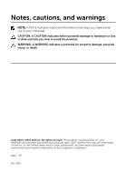
potential damage to hardware or loss of data and tells you how to avoid the problem. WARNING: A WARNING indicates a potential for property damage, personal injury, or death. Copyright © 2015 Dell Inc. All rights reserved. This product is protected by U.S. and international copyright and intellectual - Dell Inspiron 24 3452 | Service Manual - Page 3
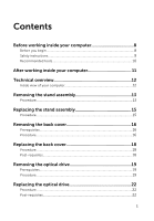
working inside your computer 8 Before you begin 8 Safety instructions 9 Recommended tools 10 After working inside your computer 11 Technical overview 12 Inside view of your computer 12 Removing the stand assembly 13 Procedure...13 Replacing the stand assembly 15 Procedure...15 Removing the - Dell Inspiron 24 3452 | Service Manual - Page 4
Removing the hard drive 23 Prerequisites...23 Procedure...23 Replacing the hard drive 26 Procedure...26 Post-requisites 26 Removing the memory module 27 Prerequisites...27 Procedure...27 Replacing the memory module 29 Procedure...29 Post-requisites 30 Removing the wireless card 31 - Dell Inspiron 24 3452 | Service Manual - Page 5
requisites 40 Removing the coin-cell battery 41 Prerequisites...41 Procedure...42 Replacing the coin-cell battery 43 Procedure...43 Post-requisites 43 Removing the microphone 44 Prerequisites...44 Procedure...44 Replacing the microphone 46 Procedure...46 Post-requisites 46 Removing the camera - Dell Inspiron 24 3452 | Service Manual - Page 6
53 Removing the VESA-mount bracket 55 Prerequisites...55 Procedure...55 Replacing the VESA-mount bracket 57 Procedure...57 Post-requisites 57 Removing the speaker cover 58 Prerequisites...58 Procedure...58 Replacing the speaker cover 60 Procedure...60 Post-requisites 60 Removing the - Dell Inspiron 24 3452 | Service Manual - Page 7
Post-requisites 66 Removing the display assembly 67 Prerequisites...67 Procedure...68 Replacing the display assembly 72 Procedure...72 Post-requisites 72 Removing the rubber feet 74 Prerequisites...74 Procedure...74 Replacing the rubber feet 76 Procedure...76 Post-requisites 76 Flashing the - Dell Inspiron 24 3452 | Service Manual - Page 8
8.1: On the Start screen, click or tap the power icon → Shut down. - Windows 7: Click or tap Start → Shut down. NOTE: If you are using a different operating system, see the documentation of your operating system for shut-down instructions. 3 Disconnect your computer and all attached devices from - Dell Inspiron 24 3452 | Service Manual - Page 9
computer, replace all covers, panels, and screws before connecting to the power source. troubleshooting and repairs as authorized or directed by the Dell technical assistance team. Damage due to servicing that is not authorized by Dell is not covered by your warranty. See the safety instructions - Dell Inspiron 24 3452 | Service Manual - Page 10
Recommended tools The procedures in this document may require the following tools: • Phillips screwdriver • Plastic scribe 10 - Dell Inspiron 24 3452 | Service Manual - Page 11
that no stray screws remain inside your computer. 2 Connect any external devices, peripherals, and cables you removed before working on your computer. 3 Replace any media cards, discs, and any other parts that you removed before working on your computer. 4 Connect your computer and all attached - Dell Inspiron 24 3452 | Service Manual - Page 12
the instructions in After working dell.com/regulatory_compliance. Inside view of your computer 1 control-buttons board 3 optical-drive assembly 5 microphone board 7 fan 9 wireless card 11 system board 13 VESA-mount bracket 2 hard-drive assembly 4 display-assembly base 6 camera module 8 heat sink 10 memory - Dell Inspiron 24 3452 | Service Manual - Page 13
your computer. After working inside your computer, follow the instructions in After working inside your computer. For more safety best practices, see the Regulatory Compliance home page at www.dell.com/regulatory_compliance. Procedure 1 Using your fingertips, lift the stand cover. - Dell Inspiron 24 3452 | Service Manual - Page 14
4 Lift the stand off the back cover. 1 stand 3 screws (2) 2 stand bracket 4 back cover 14 - Dell Inspiron 24 3452 | Service Manual - Page 15
follow the instructions in After working inside your computer. For more safety best practices, see the Regulatory Compliance home page at www.dell.com/ the back cover. 2 Replace the screws that secure the stand bracket to the back cover. 3 Slide and replace the stand cover on the stand bracket. 15 - Dell Inspiron 24 3452 | Service Manual - Page 16
inside your computer. After working inside your computer, follow the instructions in After working inside your computer. For more safety best practices, see the Regulatory Compliance home page at www.dell.com/regulatory_compliance. Prerequisites Remove the stand assembly. Procedure CAUTION - Dell Inspiron 24 3452 | Service Manual - Page 17
2 Lift the back cover off the computer. 1 display bezel 3 plastic scribe 2 back cover 17 - Dell Inspiron 24 3452 | Service Manual - Page 18
Before working inside your computer. After working inside your computer, follow the instructions in After working inside your computer. For more safety best practices, see the Regulatory Compliance home page at www.dell.com/regulatory_compliance. Procedure Align the tabs on the back cover with the - Dell Inspiron 24 3452 | Service Manual - Page 19
Regulatory Compliance home page at www.dell.com/regulatory_compliance. Prerequisites 1 Remove the stand assembly. 2 Remove the back cover. Procedure 1 Disconnect the power and data cable from the optical drive. 2 Remove the screw that secures the optical-drive assembly to the display- assembly base - Dell Inspiron 24 3452 | Service Manual - Page 20
3 Slide the optical-drive assembly out of the optical-drive bay. 1 optical-drive assembly 3 power and data cable 2 screw 4 Carefully pull the optical-drive bezel and remove it from the optical drive. 5 Remove the screw that secures the optical-drive bracket to the optical drive. 20 - Dell Inspiron 24 3452 | Service Manual - Page 21
6 Remove the optical-drive bracket from the optical drive. 1 screw 3 optical drive 2 optical-drive bracket 4 optical-drive bezel 21 - Dell Inspiron 24 3452 | Service Manual - Page 22
, follow the instructions in After working inside your computer. For more safety best practices, see the Regulatory Compliance home page at www.dell.com/regulatory_compliance. Procedure 1 Align the screw hole on the optical-drive bracket with the screw hole on the optical drive. 2 Replace the screw - Dell Inspiron 24 3452 | Service Manual - Page 23
instructions in After working inside your computer. For more safety best practices, see the Regulatory Compliance home page at www.dell.com/regulatory_compliance. CAUTION: Hard drives are fragile. Exercise care when handling the hard drive. CAUTION: To avoid data loss, do not remove the hard drive - Dell Inspiron 24 3452 | Service Manual - Page 24
3 Using your fingertips, slide and lift the hard-drive assembly out of the hard-drive bay. 1 power and data cable 3 screw 2 hard-drive assembly 4 display-assembly base 4 Remove the screws that secure the hard-drive bracket to the hard drive. 24 - Dell Inspiron 24 3452 | Service Manual - Page 25
5 Remove the hard drive from the hard-drive bracket. 1 screws (3) 3 hard-drive bracket 2 hard drive 25 - Dell Inspiron 24 3452 | Service Manual - Page 26
at www.dell.com/regulatory_compliance. CAUTION: Hard drives are fragile. Exercise care when handling the hard drive. Procedure 1 Align the screw holes on the hard-drive bracket with the screw holes on the hard drive. 2 Replace the screws that secure the hard-drive bracket to the hard drive. 3 Slide - Dell Inspiron 24 3452 | Service Manual - Page 27
working inside your computer. After working inside your computer, follow the instructions in After working inside your computer. For more safety best practices, see the Regulatory Compliance home page at www.dell.com/regulatory_compliance. Prerequisites 1 Remove the stand assembly. 2 Remove the back - Dell Inspiron 24 3452 | Service Manual - Page 28
2 Remove the memory module from the memory-module slot. 1 system board 3 memory module 2 securing clips (2) 4 memory-module slot 28 - Dell Inspiron 24 3452 | Service Manual - Page 29
Replacing the memory module WARNING: Before working inside your computer, read the safety information that shipped with your computer and follow the steps in Before working inside your computer. After working inside your computer, follow the instructions in After working inside your computer. For - Dell Inspiron 24 3452 | Service Manual - Page 30
into the slot at an angle and press the memory module down until it clicks into place. NOTE: If you do not hear the click, remove the memory module and reinstall it. 1 notch 3 securing clips (2) 5 memory-module slot Post-requisites 1 Replace the back cover. 2 Replace the stand assembly. 2 tab - Dell Inspiron 24 3452 | Service Manual - Page 31
your computer. After working inside your computer, follow the instructions in After working inside your computer. For more safety best practices, see the Regulatory Compliance home page at www.dell.com/regulatory_compliance. Prerequisites 1 Remove the stand assembly. 2 Remove - Dell Inspiron 24 3452 | Service Manual - Page 32
4 Slide the wireless card out of the wireless-card slot. 1 wireless-card bracket 3 screw 5 wireless card 2 antenna cables 4 wireless-card slot 6 system board 32 - Dell Inspiron 24 3452 | Service Manual - Page 33
instructions in After working inside your computer. For more safety best practices, see the Regulatory Compliance home page at www.dell. following table provides the antenna-cable color scheme for the wireless card supported by your computer: Connectors on the wireless card Main (white triangle) - Dell Inspiron 24 3452 | Service Manual - Page 34
6 Replace the screw that secures the wireless-card bracket and the wireless card to the system board. 1 wireless card 3 tab 5 wireless-card bracket Post-requisites 1 Replace the back cover. 2 Replace the stand assembly. 2 notch 4 antenna cables 6 screw 34 - Dell Inspiron 24 3452 | Service Manual - Page 35
your computer. After working inside your computer, follow the instructions in After working inside your computer. For more safety best practices, see the Regulatory Compliance home page at www.dell.com/regulatory_compliance. WARNING: The heat sink may become hot during normal - Dell Inspiron 24 3452 | Service Manual - Page 36
3 Lift the heat sink off the system board. 1 system board 3 heat sink 5 display-assembly base 2 captive screws (5) 4 screw 36 - Dell Inspiron 24 3452 | Service Manual - Page 37
instructions in After working inside your computer. For more safety best practices, see the Regulatory Compliance home page at www.dell are reinstalled together. If either the system board or the heat sink is replaced, use the thermal pad provided in the kit to ensure that thermal conductivity is - Dell Inspiron 24 3452 | Service Manual - Page 38
your computer. After working inside your computer, follow the instructions in After working inside your computer. For more safety best practices, see the Regulatory Compliance home page at www.dell.com/regulatory_compliance. Prerequisites 1 Remove the stand assembly. 2 Remove the - Dell Inspiron 24 3452 | Service Manual - Page 39
3 Lift the fan at an angle off the display-assembly base. 1 fan cable 3 fan 5 display-assembly base 2 system board 4 screws (2) 39 - Dell Inspiron 24 3452 | Service Manual - Page 40
inside your computer. After working inside your computer, follow the instructions in After working inside your computer. For more safety best practices, see the Regulatory Compliance home page at www.dell.com/regulatory_compliance. Procedure 1 Replace the fan at an angle on the display-assembly base - Dell Inspiron 24 3452 | Service Manual - Page 41
your computer. After working inside your computer, follow the instructions in After working inside your computer. For more safety best practices, see the Regulatory Compliance home page at www.dell.com/regulatory_compliance. CAUTION: Removing the coin-cell battery resets the BIOS - Dell Inspiron 24 3452 | Service Manual - Page 42
Procedure Using a plastic scribe, gently pry out the coin-cell battery out of the battery socket on the system board. 1 system board 3 coin-cell battery 2 plastic scribe 42 - Dell Inspiron 24 3452 | Service Manual - Page 43
working inside your computer. After working inside your computer, follow the instructions in After working inside your computer. For more safety best practices, see the Regulatory Compliance home page at www.dell.com/regulatory_compliance. Procedure With the positive-side facing up, insert the - Dell Inspiron 24 3452 | Service Manual - Page 44
inside your computer, follow the instructions in After working inside your computer. Regulatory Compliance home page at www.dell.com/regulatory_compliance. Prerequisites 1 Remove camera cable routing and remove the cable from its routing guides on the display-assembly base. 3 Follow the procedure from - Dell Inspiron 24 3452 | Service Manual - Page 45
5 Disconnect the microphone and camera cable from the microphone board. 1 microphone and camera cable 3 display bezel 5 microphone board 2 routing guides 4 display-assembly base 45 - Dell Inspiron 24 3452 | Service Manual - Page 46
instructions in After working inside your computer. For more safety best practices, see the Regulatory Compliance home page at www.dell.com from step 1 to step 3 in "Replacing the camera". 4 Route the microphone and camera cable through the routing guides on the display-assembly base. 5 Connect the - Dell Inspiron 24 3452 | Service Manual - Page 47
inside your computer, follow the instructions in After working inside your computer. Regulatory Compliance home page at www.dell.com/regulatory_compliance. Prerequisites 1 Remove camera cable routing and remove the cable from its routing guides on the display-assembly base. 3 Follow the procedure - Dell Inspiron 24 3452 | Service Manual - Page 48
7 Disconnect the microphone and camera cable from the camera module. 1 securing clip 3 camera module 2 tab 4 microphone and camera cable 48 - Dell Inspiron 24 3452 | Service Manual - Page 49
instructions in After working inside your computer. For more safety best practices, see the Regulatory Compliance home page at www.dell. from step 1 to step 2 in "Replacing the microphone". 5 Route the microphone and camera cable through the routing guides on the display-assembly base. 6 Connect - Dell Inspiron 24 3452 | Service Manual - Page 50
after you replace the system board. Prerequisites 1 Remove the stand assembly. 2 Remove the back cover. 3 Remove the memory module. 4 Remove the heat sink. 5 Remove the wireless card. Procedure 1 Disconnect the speaker, touch-control board, hard-drive data, opticaldrive data, hard-drive and optical - Dell Inspiron 24 3452 | Service Manual - Page 51
cable from its connector on the system board. 1 speaker cable 3 control-buttons board cable 5 display cable 7 hard-drive data cable 9 hard-drive and optical-drive power cable 11 microphone and camera cable 2 touch-control board cable 4 display-backlight cable 6 display-assembly base 8 optical - Dell Inspiron 24 3452 | Service Manual - Page 52
5 Carefully lift the system board from the inner edge and release the ports from the slots on the display-assembly base. 6 Lift the system board off the display-assembly base. 1 system board 3 screws (4) 2 slots 4 display-assembly base 52 - Dell Inspiron 24 3452 | Service Manual - Page 53
, touch-control board, hard-drive data, optical-drive data, hard-drive and optical-drive power, fan, and microphone and camera cables to its connectors on the system board. Post-requisites 1 Replace the wireless card. 2 Replace the heat sink. 3 Replace the memory module. 4 Replace the back cover. 53 - Dell Inspiron 24 3452 | Service Manual - Page 54
5 Replace the stand assembly. 54 - Dell Inspiron 24 3452 | Service Manual - Page 55
your computer. After working inside your computer, follow the instructions in After working inside your computer. For more safety best practices, see the Regulatory Compliance home page at www.dell.com/regulatory_compliance. Prerequisites 1 Remove the stand assembly. 2 Remove - Dell Inspiron 24 3452 | Service Manual - Page 56
3 Lift the VESA-mount bracket off the display-assembly base. 1 display-assembly base 3 VESA-mount bracket 5 routing guides 2 screws (4) 4 speaker cable 56 - Dell Inspiron 24 3452 | Service Manual - Page 57
the instructions in After working inside your computer. For more safety best practices, see the Regulatory Compliance home page at www.dell.com/regulatory_compliance. Procedure 1 Align the screw holes on the VESA-mount bracket with the screw holes on the display-assembly base. 2 Replace the screws - Dell Inspiron 24 3452 | Service Manual - Page 58
your computer. After working inside your computer, follow the instructions in After working inside your computer. For more safety best practices, see the Regulatory Compliance home page at www.dell.com/regulatory_compliance. Prerequisites 1 Remove the stand assembly. 2 Remove the - Dell Inspiron 24 3452 | Service Manual - Page 59
3 Lift the speaker cover off the display bezel. 1 screws (4) 3 display-assembly base 2 speaker cover 59 - Dell Inspiron 24 3452 | Service Manual - Page 60
working inside your computer. After working inside your computer, follow the instructions in After working inside your computer. For more safety best practices, see the Regulatory Compliance home page at www.dell.com/regulatory_compliance. Procedure 1 Align the screw holes on the speaker cover - Dell Inspiron 24 3452 | Service Manual - Page 61
your computer. After working inside your computer, follow the instructions in After working inside your computer. For more safety best practices, see the Regulatory Compliance home page at www.dell.com/regulatory_compliance. Prerequisites 1 Remove the stand assembly. 2 Remove the - Dell Inspiron 24 3452 | Service Manual - Page 62
7 Lift the speakers, along with the speaker cable, off the display bezel. 1 screw 3 speaker-cable routing 5 speaker cable 7 speakers (2) 2 tape 4 VESA-mount bracket 6 rubber grommets (4) 62 - Dell Inspiron 24 3452 | Service Manual - Page 63
instructions in After working inside your computer. For more safety best practices, see the Regulatory Compliance home page at www.dell guide on the display bezel. 3 Adhere the tape that secures the speaker cable to the VESA-mount bracket. 4 Replace the screw to the VESA-mount bracket. 5 Replace - Dell Inspiron 24 3452 | Service Manual - Page 64
inside your computer, follow the instructions in After working inside your computer. For the Regulatory Compliance home page at www.dell.com/regulatory_compliance. Prerequisites 1 Remove the stand cable routing and peel it off from its routing guides on the display-assembly base. 3 Using your - Dell Inspiron 24 3452 | Service Manual - Page 65
5 Lift the latch and disconnect the control-buttons board cable from the control-buttons board. 1 latch 3 control-buttons board cable 5 control-buttons board 2 system board 4 latch 6 securing clips (2) 65 - Dell Inspiron 24 3452 | Service Manual - Page 66
instructions in After working inside your computer. For more safety best practices, see the Regulatory Compliance home page at www.dell. the cable. 2 Replace the control-buttons board into the slot on the display bezel. 3 Route the control-buttons board cable through the routing guides and adhere the - Dell Inspiron 24 3452 | Service Manual - Page 67
the instructions in After working inside your computer. For more safety best practices, see the Regulatory Compliance home page at www.dell.com/regulatory_compliance. Prerequisites 1 Remove the stand assembly. 2 Remove the back cover. 3 Remove the optical drive. 4 Remove the hard drive. 5 Remove - Dell Inspiron 24 3452 | Service Manual - Page 68
Procedure 1 Note the optical drive and hard drive cables' routing and remove the cables from its routing guides on the display-assembly base. 1 routing guides 3 optical-drive cable 2 hard-drive cable 4 display-assembly base 68 - Dell Inspiron 24 3452 | Service Manual - Page 69
2 Remove the screws that secure the display-assembly base to the display bezel. 1 screws (19) 2 display-assembly base 3 Release the display-panel base from the tabs on the display bezel. 4 Slide the display cable through the slot on the display-assembly base. 69 - Dell Inspiron 24 3452 | Service Manual - Page 70
5 Lift the display-assembly base off the display panel. 1 tabs (6) 3 display cable 2 display-assembly base 4 slot 70 - Dell Inspiron 24 3452 | Service Manual - Page 71
1 display assembly 71 - Dell Inspiron 24 3452 | Service Manual - Page 72
cover. 4 Replace the VESA-mount bracket. 5 Replace the system board. 6 Replace the camera. 7 Replace the microphone. 8 Replace the fan. 9 Replace the heat sink. 10 Replace the wireless card. 11 Replace the memory module. 12 Replace the hard drive. 13 Replace the optical drive. 14 Replace the back - Dell Inspiron 24 3452 | Service Manual - Page 73
15 Replace the stand assembly. 73 - Dell Inspiron 24 3452 | Service Manual - Page 74
the instructions in After working inside your computer. For more safety best practices, see the Regulatory Compliance home page at www.dell.com/regulatory_compliance. Prerequisites 1 Remove the stand assembly. 2 Remove the back cover. 3 Remove the optical drive. 4 Remove the hard drive. 5 Remove - Dell Inspiron 24 3452 | Service Manual - Page 75
2 Lift the rubber feet off the display bezel. 1 rubber feet (2) 3 display bezel 2 screws (2) 75 - Dell Inspiron 24 3452 | Service Manual - Page 76
mount bracket. 6 Replace the system board. 7 Replace the camera. 8 Replace the microphone. 9 Replace the fan. 10 Replace the heat sink. 11 Replace the wireless card. 12 Replace the memory module. 13 Replace the hard drive. 14 Replace the optical drive. 15 Replace the back cover. 16 Replace the stand - Dell Inspiron 24 3452 | Service Manual - Page 77
the computer. 2 Go to www.dell.com/support. 3 Click Product Support, enter the Service Tag of your computer and click Submit. NOTE: If you do not have the Service Tag, use the auto-detect feature or manually browse for your computer model. 4 Click Drivers & downloads. 5 Select the operating system
-
 1
1 -
 2
2 -
 3
3 -
 4
4 -
 5
5 -
 6
6 -
 7
7 -
8
-
9
-
10
-
11
-
12
-
13
-
14
-
15
-
16
-
17
-
18
-
19
-
20
-
21
-
22
-
23
-
24
-
25
-
26
-
27
-
28
-
29
-
30
-
31
-
32
-
33
-
34
-
35
-
36
-
37
-
38
-
39
-
40
-
41
-
42
-
43
-
44
-
45
-
46
-
47
-
48
-
49
-
50
-
51
-
52
-
53
-
54
-
55
-
56
-
57
-
58
-
59
-
60
-
61
-
62
-
63
-
64
-
65
-
66
-
67
-
68
-
69
-
70
-
71
-
72
-
73
-
74
-
75
-
76
-
77
 |
 |

Inspiron 24
3000 Series
Service Manual
Computer Model: Inspiron 24–3452
Regulatory Model: W12C
Regulatory Type: W12C002