Dell OptiPlex 380 Service Manual
Dell OptiPlex 380 Manual
 |
View all Dell OptiPlex 380 manuals
Add to My Manuals
Save this manual to your list of manuals |
Dell OptiPlex 380 manual content summary:
- Dell OptiPlex 380 | Service Manual - Page 1
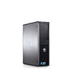
Dell™ OptiPlex™ 380 Service Manual-Mini-Tower Working on Your Computer Specifications Removing and Replacing Parts System Board Layout System Setup Diagnostics Notes, Cautions, and Warnings NOTE: A NOTE indicates important information that helps you make better use of your computer. CAUTION: A - Dell OptiPlex 380 | Service Manual - Page 2
Setup Dell™ OptiPlex™ 380 Service Manual-Mini-Tower Boot Menu Navigation Keystrokes Entering System Setup System Setup Simulation System Setup Menu Options Boot Menu Press when the Dell™ logo appears to initiate a one-time boot menu with a list of the valid boot devices for the computer - Dell OptiPlex 380 | Service Manual - Page 3
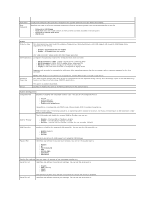
field determines how the BIOS configures floppy drives, Operating Systems with USB support will recognize USB Floppy drives regardless of this setting: l Disable - All Floppy drive are disable l Enable - All floppy drive are enable. The "USB Controller" Setup option will affect floppy operation - Dell OptiPlex 380 | Service Manual - Page 4
) - Use the add-in video controller. l Onboard/Card - Use the integrated video controller unless a Graphic care is installed. A PCI Express Graphic(PEG) card will override and disable the integrated video controller. Performance Multi Core Support Intel® SpeedStep™ This field specifies whether - Dell OptiPlex 380 | Service Manual - Page 5
mode is enabled, the integrated network card is disabled when the computer shutsdown or hibernates. Only add-in network cards will be able to remotely wake the computer. Remote Wakeup Allows the computer to power up when a network interface controller receives a wake up signal. You can set Remote - Dell OptiPlex 380 | Service Manual - Page 6
keyboard error reporting when the computer starts. This option is enabled by default. MEBx Hotkey sign-on displays a message stating the keystroke sequence required to enter the Manageability Engine BIOS Extensions(MEBx) Setup program. This option is enabled by default. Set the maximum memory for - Dell OptiPlex 380 | Service Manual - Page 7
Coin-Cell Battery Dell™ OptiPlex™ 380 Service Manual-Mini-Tower WARNING: Before working inside your computer, read the safety information that shipped with your computer. For additional safety best practices information, see the Regulatory Compliance Homepage at www.dell.com/regulatory_compliance - Dell OptiPlex 380 | Service Manual - Page 8
Replacing the Coin-Cell Battery To replace the coin-cell battery, perform the above steps in reverse order. Back to Contents Page - Dell OptiPlex 380 | Service Manual - Page 9
Contents Page Cover Dell™ OptiPlex™ 380 Service Manual-Mini-Tower WARNING: Before working inside your computer, read the safety information that shipped with your computer. For additional safety best practices information, see the Regulatory Compliance Homepage at www.dell.com/regulatory_compliance - Dell OptiPlex 380 | Service Manual - Page 10
4. Remove the cover from the computer. Replacing the Cover To replace the cover, perform the above steps in reverse order. Back to Contents Page - Dell OptiPlex 380 | Service Manual - Page 11
Dell™ OptiPlex™ 380 Service Manual-Desktop Dell Diagnostics Power Button Light Codes Beep Codes Diagnostic Lights Dell Diagnostics When to Use the Dell Diagnostics It is recommended that you print these procedures before you begin. NOTE: The Dell Diagnostics software works only on Dell computers - Dell OptiPlex 380 | Service Manual - Page 12
power but a device such as a memory module or graphics card might be malfunctioning or incorrectly installed. Solid Amber Indicates the computer is facing the power issue or an internal device is malfunctioning. Beep Codes If the monitor cannot display error messages during the POST, the computer - Dell OptiPlex 380 | Service Manual - Page 13
to the operating system. Light Pattern Problem Description The computer is in a normal off condition or a possible pre-BIOS failure has occurred. Suggested Resolution l Plug the computer into a working electrical outlet. l If the problem persists, contact Dell. The diagnostic lights are not lit - Dell OptiPlex 380 | Service Manual - Page 14
Page Drive Bezel Dell™ OptiPlex™ 380 Service Manual-Mini-Tower WARNING: Before working inside your computer, read the safety information that shipped with your computer. For additional safety best practices information, see the Regulatory Compliance Homepage at www.dell.com/regulatory_compliance - Dell OptiPlex 380 | Service Manual - Page 15
Replacing the Drive Bezel To replace the drive bezel, perform the above steps in reverse order. Back to Contents Page - Dell OptiPlex 380 | Service Manual - Page 16
Page Hard Drive Dell™ OptiPlex™ 380 Service Manual-Mini-Tower WARNING: Before working inside your computer, read the safety information that shipped with your computer. For additional safety best practices information, see the Regulatory Compliance Homepage at www.dell.com/regulatory_compliance - Dell OptiPlex 380 | Service Manual - Page 17
5. Press in on the blue release tabs on each side of the hard drive and slide the hard drive out of the computer. Replacing the Hard Drive To replace the hard drive, perform the above steps in reverse order. Back to Contents Page - Dell OptiPlex 380 | Service Manual - Page 18
Page Heat Sink Dell™ OptiPlex™ 380 Service Manual-Mini-Tower WARNING: Before working inside your computer, read the safety information that shipped with your computer. For additional safety best practices information, see the Regulatory Compliance Homepage at www.dell.com/regulatory_compliance - Dell OptiPlex 380 | Service Manual - Page 19
Replacing the Heat Sink To replace the heat sink, perform the above steps in reverse order. Back to Contents Page - Dell OptiPlex 380 | Service Manual - Page 20
Page I/O Panel Dell™ OptiPlex™ 380 Service Manual-Mini-Tower WARNING: Before working inside your computer, read the safety information that shipped with your computer. For additional safety best practices information, see the Regulatory Compliance Homepage at www.dell.com/regulatory_compliance - Dell OptiPlex 380 | Service Manual - Page 21
4. Remove the screw that secures the I/O panel to the front of the computer. 5. Press the retention latch to release the I/O panel from the chassis. - Dell OptiPlex 380 | Service Manual - Page 22
6. Tilt the I/O panel toward the back of the computer. 7. Lift the I/O panel out of the slot. - Dell OptiPlex 380 | Service Manual - Page 23
8. Disconnect the data cable from the I/O panel. 9. Remove the I/O panel from the computer. - Dell OptiPlex 380 | Service Manual - Page 24
Replacing the I/O Panel To replace the I/O panel, perform the above steps in reverse order. Back to Contents Page - Dell OptiPlex 380 | Service Manual - Page 25
Contents Page Memory Dell™ OptiPlex™ 380 Service Manual-Mini-Tower WARNING: Before working inside your computer, read the safety information that shipped with your computer. For additional safety best practices information, see the Regulatory Compliance Homepage at www.dell.com/regulatory_compliance - Dell OptiPlex 380 | Service Manual - Page 26
Replacing the Memory Module(s) To replace the memory module(s), perform the above steps in reverse order. Back to Contents Page - Dell OptiPlex 380 | Service Manual - Page 27
Back to Contents Page Removing and Replacing Parts Dell™ OptiPlex™ 380 Service Manual-Mini-Tower Cover Coin-Cell Battery Optical Drive Video Card Hard Drive Power Supply System Board Drive Bezel Memory Module Fan I/O Panel Heat Sink Processor Back to Contents Page - Dell OptiPlex 380 | Service Manual - Page 28
Page Optical Drive Dell™ OptiPlex™ 380 Service Manual-Mini-Tower WARNING: Before working inside your computer, read the safety information that shipped with your computer. For additional safety best practices information, see the Regulatory Compliance Homepage at www.dell.com/regulatory_compliance - Dell OptiPlex 380 | Service Manual - Page 29
5. Slide the drive release latch towards the bottom of the computer and slide the optical drive out of the computer. Replacing the Optical Drive To replace the optical drive, perform the above steps in reverse order. Back to Contents Page - Dell OptiPlex 380 | Service Manual - Page 30
Page Power Supply Dell™ OptiPlex™ 380 Service Manual-Mini-Tower WARNING: Before working inside your computer, read the safety information that shipped with your computer. For additional safety best practices information, see the Regulatory Compliance Homepage at www.dell.com/regulatory_compliance - Dell OptiPlex 380 | Service Manual - Page 31
4. Disconnect the optical-drive power cable from the optical drive. 5. Disconnect the processor power cable from the system board. - Dell OptiPlex 380 | Service Manual - Page 32
6. Disconnect the main power cable from the system board. 7. Remove the I/O-panel data cable from the cable routing clip at the base of the power supply. - Dell OptiPlex 380 | Service Manual - Page 33
8. Remove any data cables from the cable routing at the base of the power supply. 9. Press the release latch that secures the power supply to the chassis. - Dell OptiPlex 380 | Service Manual - Page 34
10. Slide the power supply towards the front of the computer and lift the power supply up and away from the computer. Replacing the Power Supply To replace the power supply, perform the above steps in reverse order. Back to Contents Page - Dell OptiPlex 380 | Service Manual - Page 35
Page Processor Dell™ OptiPlex™ 380 Service Manual-Mini-Tower WARNING: Before working inside your computer, read the safety information that shipped with your computer. For additional safety best practices information, see the Regulatory Compliance Homepage at www.dell.com/regulatory_compliance - Dell OptiPlex 380 | Service Manual - Page 36
4. Remove the processor from its socket on the system board. CAUTION: When replacing the processor, do not touch any of the pins inside the socket or allow any objects to fall on the pins in the socket. Replacing the Processor To replace the processor, perform the above steps in reverse order. Back - Dell OptiPlex 380 | Service Manual - Page 37
Back to Contents Page Specifications Dell™ OptiPlex™ 380 Service Manual-Mini-Tower System Information Memory Audio Expansion Bus Drives System Board Connectors Physical Processor Video Network Cards External Connectors Power Environmental NOTE: Offerings may vary by region. For more information - Dell OptiPlex 380 | Service Manual - Page 38
width (maximum) Serial ATA Memory Processor fan System fan Front panel control/front panel audio Processor Power 12V Power 120-pin connector 32 bits 164-pin connector 16 PCI-Express lanes Mini-tower - three 7-pin connectors Desktop - three 7-pin connectors Small form factor - two 7-pin connectors - Dell OptiPlex 380 | Service Manual - Page 39
Physical Mini-Tower Desktop Small Form Factor Environmental Temperature: Operating Storage Relative humidity (noncondensing) Maximum vibration: Operating Storage Maximum shock: Operating Storage Altitude: Operating Storage Airborne contaminant level Height 40.8 cm (16.1 - Dell OptiPlex 380 | Service Manual - Page 40
Back to Contents Page System Board Layout Dell™ OptiPlex™ 380 Service Manual-Mini-Tower 1 speaker connector (INT_SPKR) 3 processor power connector (12V POWER) 5 SATA drive connectors (SATA0 and SATA1) 7 power connector (POWER) 9 intruder connector (INTRUDER) 11 password jumper (PSWD) 13 coin-cell - Dell OptiPlex 380 | Service Manual - Page 41
Page System Board Dell™ OptiPlex™ 380 Service Manual-Mini-Tower WARNING: Before working inside your computer, read the safety information that shipped with your computer. For additional safety best practices information, see the Regulatory Compliance Homepage at www.dell.com/regulatory_compliance - Dell OptiPlex 380 | Service Manual - Page 42
7. Disconnect the system board power cable. 8. Disconnect the optical-drive data cable from the system board. - Dell OptiPlex 380 | Service Manual - Page 43
9. Disconnect the hard-drive data cable from the system board. 10. Disconnect the I/O-panel data cable from the system board. - Dell OptiPlex 380 | Service Manual - Page 44
11. Remove the two screws that secure the heat sink assembly bracket to the system board. 12. Remove the heat sink assembly bracket from the computer. - Dell OptiPlex 380 | Service Manual - Page 45
13. Remove the seven screws that secure the system board to the chassis. 14. Remove the system board from the chassis. - Dell OptiPlex 380 | Service Manual - Page 46
Replacing the System Board To replace the system board, perform the above steps in reverse order. Back to Contents Page - Dell OptiPlex 380 | Service Manual - Page 47
to Contents Page Fan Dell™ OptiPlex™ 380 Service Manual-Mini-Tower WARNING: Before working inside your computer, read the safety information that shipped with your computer. For additional safety best practices information, see the Regulatory Compliance Homepage at www.dell.com/regulatory_compliance - Dell OptiPlex 380 | Service Manual - Page 48
4. Disconnect the fan power cable from the system board. 5. Pull up on the retention tab that is closest to the top of the computer. - Dell OptiPlex 380 | Service Manual - Page 49
6. Press the fan retention tab that is closest to the base of the computer. 7. Slide the fan towards the back of the computer. - Dell OptiPlex 380 | Service Manual - Page 50
8. Remove the fan from the computer. Replacing the Fan To replace the fan, perform the above steps in reverse order. Back to Contents Page - Dell OptiPlex 380 | Service Manual - Page 51
Page Video Card Dell™ OptiPlex™ 380 Service Manual-Mini-Tower WARNING: Before working inside your computer, read the safety information that shipped with your computer. For additional safety best practices information, see the Regulatory Compliance Homepage at www.dell.com/regulatory_compliance - Dell OptiPlex 380 | Service Manual - Page 52
4. Lift the expansion card up and out of the expansion slot. Replacing the Video Card To replace the video card, perform the above steps in reverse order. Back to Contents Page - Dell OptiPlex 380 | Service Manual - Page 53
Back to Contents Page Working on Your Computer Dell™ OptiPlex™ 380 Service Manual-Mini-Tower Before Working Inside Your Computer Recommended Tools Turning Off Your Computer After Working Inside Your Computer Before Working Inside Your Computer Use the following safety guidelines to help protect your - Dell OptiPlex 380 | Service Manual - Page 54
and then plug it into the computer. 2. Connect any telephone or network cables to your computer. 3. Connect your computer and all attached devices to their electrical outlets. 4. Turn on your computer. 5. Verify that the computer works correctly by running the Dell Diagnostics. Back to Contents Page
-
 1
1 -
 2
2 -
 3
3 -
 4
4 -
 5
5 -
 6
6 -
 7
7 -
8
-
9
-
10
-
11
-
12
-
13
-
14
-
15
-
16
-
17
-
18
-
19
-
20
-
21
-
22
-
23
-
24
-
25
-
26
-
27
-
28
-
29
-
30
-
31
-
32
-
33
-
34
-
35
-
36
-
37
-
38
-
39
-
40
-
41
-
42
-
43
-
44
-
45
-
46
-
47
-
48
-
49
-
50
-
51
-
52
-
53
-
54
 |
 |

Dell™ OptiPlex™ 380 Service Manual—
Mini-Tower
Notes, Cautions, and Warnings
If you purchased a Dell™ n Series computer, any references in this document to Microsoft®
Windows
®
operating systems are not applicable.
Information in this document is subject to change without notice.
© 2010 Dell Inc. All rights reserved.
Reproduction of this material in any manner whatsoever without the written permission of Dell Inc. is strictly forbidden.
Other trademarks and trade names may be used in this document to refer to either the entities claiming the marks and names or their products. Dell Inc. disclaims any
proprietary interest in trademarks and trade names other than its own.
March 2010
Rev. A01
Working on Your Computer
Specifications
Removing and Replacing Parts
System Board Layout
System Setup
Diagnostics
NOTE:
A NOTE indicates important information that helps you make better use of your computer.
CAUTION:
A CAUTION indicates potential damage to hardware or loss of data if instructions are not followed.
WARNING:
A WARNING indicates a potential for property damage, personal injury, or death.
Trademarks used in this text:
Dell
, the
DELL
logo,
and OptiPlex
are trademarks of Dell Inc.;
ATI Radeon
is a trademarks of
Advanced Micro Devices, Inc;
Intel
,
Pentium
,
Celeron,
and
Core
are either trademarks or registered trademarks of Intel Corporation;
Microsoft
,
Windows,
Windows Vista
,
and the
Windows Vista
start button
are either trademarks or registered trademarks of Microsoft Corporation in the United
States and/or other countries.