Dell OptiPlex 9020M Dell OptiPlex 9020M Owners Manual
Dell OptiPlex 9020M Manual
 |
View all Dell OptiPlex 9020M manuals
Add to My Manuals
Save this manual to your list of manuals |
Dell OptiPlex 9020M manual content summary:
- Dell OptiPlex 9020M | Dell OptiPlex 9020M Owners Manual - Page 1
Dell OptiPlex 9020M Owner's Manual Regulatory Model: D09U Regulatory Type: D09U001 - Dell OptiPlex 9020M | Dell OptiPlex 9020M Owners Manual - Page 2
potential damage to hardware or loss of data and tells you how to avoid the problem. WARNING: A WARNING indicates a potential for property damage, personal injury, or death. Copyright © 2014 Dell Inc. All rights reserved. This product is protected by U.S. and international copyright and intellectual - Dell OptiPlex 9020M | Dell OptiPlex 9020M Owners Manual - Page 3
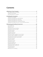
the Power Adapter...8 Installing the Dell OptiPlex Micro Dual VESA Mount 9 Installing the Dell OptiPlex Micro VESA Mount 11 Installing the Dell OptiPlex Micro Vertical Stand 12 Installing the Dell OptiPlex Micro Console with DVD-RW 13 Installing the Dell OptiPlex Micro All-in-One Mount - Dell OptiPlex 9020M | Dell OptiPlex 9020M Owners Manual - Page 4
the System Board...35 Installing the System Board...36 4 System Setup...37 Boot Sequence...37 Navigation Keys...37 System Setup Options...38 Updating the BIOS ...48 Jumper Settings...48 System and Setup Password...49 Assigning a System Password and Setup Password 49 Deleting or Changing an Existing - Dell OptiPlex 9020M | Dell OptiPlex 9020M Owners Manual - Page 5
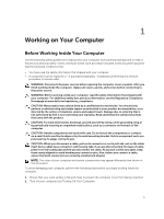
all power sources troubleshooting and simple repairs as authorized in your product documentation, or as directed by the online or telephone service and support team. Damage due to servicing that is not authorized by Dell is not covered by your warranty. Read and follow the safety instructions - Dell OptiPlex 9020M | Dell OptiPlex 9020M Owners Manual - Page 6
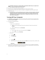
cable from your computer and then unplug the cable from the network device. 3. Disconnect all network cables from the computer. 4. Disconnect your computer and all attached devices from their electrical outlets. 5. Press and hold the power button while the computer is unplugged to ground the system - Dell OptiPlex 9020M | Dell OptiPlex 9020M Owners Manual - Page 7
the network device and then plug it into the computer. 2. Connect any telephone or network cables to your computer. 3. Connect your computer and all attached devices to their electrical outlets. 4. Turn on your computer. 5. If required, verify that the computer works correctly by running the Dell - Dell OptiPlex 9020M | Dell OptiPlex 9020M Owners Manual - Page 8
install the following accessories: • Power Adapter • Dell OptiPlex Micro Dual VESA Mount • Dell OptiPlex Micro VESA Mount • Dell OptiPlex Micro Vertical Stand • Dell OptiPlex Micro Console with DVD-RW • Dell OptiPlex Micro All-in-One Mount Installing the Power Adapter 1. Perform the following steps - Dell OptiPlex 9020M | Dell OptiPlex 9020M Owners Manual - Page 9
Installing the Dell OptiPlex Micro Dual VESA Mount Recommended Screws: Screw Type M4 x L10 mm, Pan head screw Used in Monitor Prerequisite: Install the power adapter. 1. Align the dual VESA mount behind the monitor and tighten the screws to secure the dual VESA mount to the monitor. 2. Perform - Dell OptiPlex 9020M | Dell OptiPlex 9020M Owners Manual - Page 10
3. Slide the power adapter case through the grooves at the bottom of the dual dual VESA mount to lock it. 4. Connect all the cables and antenna to the computer. 10 - Dell OptiPlex 9020M | Dell OptiPlex 9020M Owners Manual - Page 11
5. Tighten the screws to secure the arm stand to the dual VESA mount. Installing the Dell OptiPlex Micro VESA Mount Recommended Screws: Screw Type M4 x L10 mm, Pan head screw Used in Monitor 11 - Dell OptiPlex 9020M | Dell OptiPlex 9020M Owners Manual - Page 12
following steps as shown in the illustration: a. Slide the power adapter case through the grooves at the bottom of the VESA mount to lock it. b. Connect all the cables and install antenna to the computer. Installing the Dell OptiPlex Micro Vertical Stand Align the computer on the vertical stand and - Dell OptiPlex 9020M | Dell OptiPlex 9020M Owners Manual - Page 13
Installing the Dell OptiPlex Micro Console with DVD-RW Recommended Screws: Screw Type ST4 x 13 mm, Wooden screw Used in Wooden table 1. Perform the following steps as shown in the - Dell OptiPlex 9020M | Dell OptiPlex 9020M Owners Manual - Page 14
to the optical drive console [2]. 3. Perform the following steps as shown in the illustration: a. Cut the strap of the power adapter cable [1]. b. Slide and insert the power adapter into the slot [2]. c. Route the cable through the notch to secure it [3]. 4. Perform the following steps as shown in - Dell OptiPlex 9020M | Dell OptiPlex 9020M Owners Manual - Page 15
5. Route the USB cables through the cable management clip and connect them to the computer. Close the cable management clip. 6. Perform the following steps as shown in the illustration: a. Prepare the wooden table by installing screws for mounting the optical drive console. b. Align the slots on the - Dell OptiPlex 9020M | Dell OptiPlex 9020M Owners Manual - Page 16
7. Install the antenna to the optical drive console. 8. Perform the following steps as shown in the illustration: a. Slide and insert the cover to its position [1]. b. Tighten the screws to secure the cover to the chassis [2]. 16 - Dell OptiPlex 9020M | Dell OptiPlex 9020M Owners Manual - Page 17
the Dell OptiPlex Micro All-in-One Mount Behind the Monitor Recommended Screws: Screw Type M4 X L8 mm, pitch 0.7 mm, selftapping screw Used with PUZ plate without thread screw holes- Dell P,U,PU,UZ- series monitors M4 X L8 mm, pitch 0.5 mm, machine screw PUZ plate with thread screw holes - Dell - Dell OptiPlex 9020M | Dell OptiPlex 9020M Owners Manual - Page 18
M3 X L8 mm, pitch 0.5 mm, self- E Plate without thread screw tapping screw holes- Dell E-series monitors M3 X L8 mm, pitch 0.35 mm, machine screw E Plate with thread screw holes- Dell E-series monitors U Plate - Universal monitors 1. Perform the following steps as shown in the illustration: a. - Dell OptiPlex 9020M | Dell OptiPlex 9020M Owners Manual - Page 19
2. Perform the following steps as shown in the illustration: a. Slide the computer into the slot [1]. b. Rotate the screw in clockwise direction to secure the computer to the chassis [2]. 3. Perform the following steps as shown in the illustration: a. Lift up the antenna cable [1]. b. Connect the - Dell OptiPlex 9020M | Dell OptiPlex 9020M Owners Manual - Page 20
4. Perform the following steps as shown in the illustration: a. Cut the strap of power adapter cable [1]. b. Slide the power adapter into the slot [2]. c. Route the cable through the clip [3]. 5. Perform the following steps as shown in the illustration: a. Route the cable through the clip [1]. b. - Dell OptiPlex 9020M | Dell OptiPlex 9020M Owners Manual - Page 21
6. Align the PUZ plate to the bottom of monitor and tighten the screws. 7. Perform the following steps as shown in the illustration: a. Slide and lock the chassis to the PUZ plate [1]. b. Rotate the screw in clockwise direction to secure the computer [2]. c. Flip the computer along with the monitor - Dell OptiPlex 9020M | Dell OptiPlex 9020M Owners Manual - Page 22
8. Perform the following steps as shown in the illustration: a. Connect all the cables to the computer. b. Slide the cover to its original position [1]. c. Tighten the screws to secure the cover to the chassis [2]. 22 - Dell OptiPlex 9020M | Dell OptiPlex 9020M Owners Manual - Page 23
13. network connector (Integrated Connector Module) 15. DisplayPort connector 2. hard-drive activity light 4. microphone connector 6. HDMI or display port or PS2 and serial connector (optional) 8. security-cable slot 10. USB 3.0 connectors 12. service tag 14. VGA connector 16. power cable connector - Dell OptiPlex 9020M | Dell OptiPlex 9020M Owners Manual - Page 24
3. Perform the following steps as shown in the illustration: a. Remove the screw that secures the cover to the computer [1]. b. Slide the cover outwards [2]. c. Lift the cover up to remove it from the computer [3]. Installing the Cover 1. Align the cover to its original position on the computer. 2. - Dell OptiPlex 9020M | Dell OptiPlex 9020M Owners Manual - Page 25
Removing the Processor Fan Module 1. Follow the procedures in Before Working Inside Your Computer. 2. Remove the cover. 3. Perform the following steps as shown in the illustration: a. Press the securing tabs on the sides [1]. b. Slide the processor fan module outwards [2]. c. Lift the processor fan - Dell OptiPlex 9020M | Dell OptiPlex 9020M Owners Manual - Page 26
Installing the Processor Fan Module 1. Connect the speaker and fan cable to the connectors on the system board. 2. Place the processor fan module on the slot and slide it until it is secured. 3. Install the cover. 4. Follow the procedures in After Working Inside Your Computer. Removing the Speaker - Dell OptiPlex 9020M | Dell OptiPlex 9020M Owners Manual - Page 27
2. Remove the cover. 3. Perform the following steps as shown in the illustration: a. Press the securing tabs to release the hard-drive assembly [1]. b. Slide the hard-drive assembly to release it from the slot [2]. c. Lift the hard-drive assembly away from the computer [3]. 4. Perform the following - Dell OptiPlex 9020M | Dell OptiPlex 9020M Owners Manual - Page 28
-drive assembly to its slot on the computer. 3. Install the cover. 4. Follow the procedures in After Working Inside Your Computer. Removing the HDMI or DisplayPort Connector Board 1. Follow the procedures in Before Working Inside Your Computer. 2. Remove the cover. 3. Perform the following steps as - Dell OptiPlex 9020M | Dell OptiPlex 9020M Owners Manual - Page 29
or DisplayPort connector board into its slot. 2. Tighten the screws to secure the HDMI or DisplayPort connector board to the base panel. 3. Connect the cable to the HDMI or DisplayPort connector board. 4. Install the cover. 5. Follow the procedures in After Working Inside Your Computer. Removing - Dell OptiPlex 9020M | Dell OptiPlex 9020M Owners Manual - Page 30
Installing the PS2 and Serial Connector Board 1. Place the PS2 and serial connector board into its slot. 2. Tighten the screws that secure the PS2 and serial connector board to the base panel. 3. Connect the cable to the PS2 and serial connector board. 4. Install the cover. 5. Follow the procedures - Dell OptiPlex 9020M | Dell OptiPlex 9020M Owners Manual - Page 31
from its socket [3]. Installing the Processor 1. Insert the processor into the processor socket. Ensure that the processor is properly seated. 2. Press the release lever down and then move it inward to secure it with the retention hook. 3. Install the: a. hard drive b. cover 4. Follow the procedures - Dell OptiPlex 9020M | Dell OptiPlex 9020M Owners Manual - Page 32
WLAN card to the system board. 5. Install: a. hard drive b. cover 6. Follow the procedures in After Working Inside Your Computer. Removing the M.2 SSD or DDPE Card 1. Follow the procedures in Before Working Inside Your Computer. 2. Remove the: a. cover b. hard drive 3. Perform the following steps - Dell OptiPlex 9020M | Dell OptiPlex 9020M Owners Manual - Page 33
memory module until it pops-up. Lift and remove the memory module from its connector. Installing the Memory NOTE: Please use DIMM 2 slot if there is only one memory module available. 1. Align the notch on the memory cover b. hard drive c. HDMI board 3. Press the release latch away from the battery. - Dell OptiPlex 9020M | Dell OptiPlex 9020M Owners Manual - Page 34
Place the coin-cell battery into its slot on the system board. 2. Press the coin-cell battery downward to secure it. 3. Install the: a. HDMI board b. hard drive c. cover 4. Follow the procedures in After Working Inside Your Computer. System Board Layout The following image displays the system board - Dell OptiPlex 9020M | Dell OptiPlex 9020M Owners Manual - Page 35
procedures in Before Working Inside Your Computer. 2. Remove the: a. cover b. processor fan module c. hard drive d. heatsink e. memory f. processor g. HDMI board h. PS2 and serial connector board i. M.2 SSD or DDPE card j. WLAN card k. coin-cell battery 3. Perform the following steps as shown in the - Dell OptiPlex 9020M | Dell OptiPlex 9020M Owners Manual - Page 36
as shown in the illustration. a. Slide the system board to release it from the computer [1,2]. b. Lift the system board away from coin-cell battery b. WLAN card c. M.2 SSD or DDPE card d. HDMI board e. PS2 and serial connector board f. processor g. memory h. heatsink i. hard drive j. processor fan - Dell OptiPlex 9020M | Dell OptiPlex 9020M Owners Manual - Page 37
you to manage your computer hardware and specify BIOS‐level options. From the System Setup, you can specific device (for example: optical drive or hard drive). During the Power-on Self Test (POST), when the Dell logo appears, you can: • Access System Setup by pressing key • Bring up the one - Dell OptiPlex 9020M | Dell OptiPlex 9020M Owners Manual - Page 38
Information - Displays BIOS Version, Service Tag, Asset Tag, Ownership Tag, Ownership Date, Manufacture Date, Express Service Code, and Signed Firmware Update is enabled. • Memory Information - Displays Memory Installed, Memory Available, Memory Speed, Memory Channels Mode, Memory Technology, DIMM - Dell OptiPlex 9020M | Dell OptiPlex 9020M Owners Manual - Page 39
date and time takes effect immediately. Table 3. System Configuration Option Integrated NIC Description Allows you to enable or disable the integrated network card. You can set the integrated NIC to: • Enable UEFI Network to support RAID mode specification. • Enable SMART Reporting - This option - Dell OptiPlex 9020M | Dell OptiPlex 9020M Owners Manual - Page 40
Option Admin Password System Password Description This field configures the integrated USB controller. If Boot Support is enabled, the system is allowed to boot any type of USB mass storage devices (HDD, memory key, floppy). If USB port is enabled, device attached to this port is enabled and - Dell OptiPlex 9020M | Dell OptiPlex 9020M Owners Manual - Page 41
Mini-card SSD Password Strong Password This option will appear if your computer has an M-SATA SSD Max • System Password Min • System Password Max the system and internal HDD passwords when powered on from the off state (a cold boot the BIOS module interface of the optional Computrace Service from - Dell OptiPlex 9020M | Dell OptiPlex 9020M Owners Manual - Page 42
Enable CPU XD Support - This option is enabled by default. Allows you to determine if you access the Option Read Only Memory (OROM) configuration screens BIOS Extension (CTRL+P/F12). • Enable - User may enter OROM configuration screens via the hotkey. This option is selected by default. • One- - Dell OptiPlex 9020M | Dell OptiPlex 9020M Owners Manual - Page 43
Support Specifies whether the process will have one or all cores enabled. The performance the processor Standard CPUID Function will support. • Enable CPUID Limit - This not allow the TurboBoost driver to increase the performance state Allows the Intel TurboBoost driver to increase the performance - Dell OptiPlex 9020M | Dell OptiPlex 9020M Owners Manual - Page 44
you turn off your computer using the switch on a power strip or surge protector or if Auto Power is set to disabled. Allows you to define the controls to a specific rear USB port(next to RJ45 connector). • USB Wake Support From Standby is enabled by default. • USB Wake Support From Hibernation - Dell OptiPlex 9020M | Dell OptiPlex 9020M Owners Manual - Page 45
AC power supply. The options differ based on the form factor. • Disabled - Does not allow the system to power on setup (BIOS) warning messages when you use certain power adapters. • Enable Adapter Warnings by default Table 9. Virtualization Support Option Description Virtualization This option - Dell OptiPlex 9020M | Dell OptiPlex 9020M Owners Manual - Page 46
default. Description Allows you to enable or disable the internal wireless devices. • WLAN/WiGig • Bluetooth All options are enabled by default. Description Displays the service tag of your computer. Allows you to create a system asset tag if an asset tag is not already set. This option is not set - Dell OptiPlex 9020M | Dell OptiPlex 9020M Owners Manual - Page 47
Option Server IP Address Server Port Client Address Method Client IP Address Client SubnetMask Client Gateway DNS IP Address Domain Name Advanced Description Specifies the primary static IP address of the Cloud Desktop server with which the client software communicates. The default IP address is - Dell OptiPlex 9020M | Dell OptiPlex 9020M Owners Manual - Page 48
the BIOS It is recommended to update your BIOS (system setup), on replacing the system board or if an update is available. For laptops, ensure that your computer battery is fully charged and connected to a power outlet 1. Re-start the computer. 2. Go to dell.com/support. 3. Enter the Service Tag - Dell OptiPlex 9020M | Dell OptiPlex 9020M Owners Manual - Page 49
need not provide the system password to log on to the computer. To enter a system setup, press immediately after a power-on or re-boot. 1. In the System BIOS or System Setup screen, select System Security and press . The System Security screen appears. 2. In the System Security screen - Dell OptiPlex 9020M | Dell OptiPlex 9020M Owners Manual - Page 50
System or Setup password, if the Password Status is Locked. To enter the System Setup, press immediately after a power-on or reboot. 1. In the System BIOS or System Setup screen, select System Security and press . The System Security screen is displayed. 2. In the System Security - Dell OptiPlex 9020M | Dell OptiPlex 9020M Owners Manual - Page 51
capacity Minimum memory Maximum memory Specification DDR3 1600 MHz two DIMM slots 2 GB, 4 GB, and 8 GB 2 GB 16 GB Table 17. Video Feature Integrated Specification Intel HD Graphics Table 18. Audio Feature Integrated Specification Realtek HDA Codec ALC3234 Table 19. Network Feature Integrated - Dell OptiPlex 9020M | Dell OptiPlex 9020M Owners Manual - Page 52
Network adapter Serial USB 2.0 (Front/Rear/Internal) USB 3.0 (Front/Rear/Internal) Video 52 Specification Intel Q87 chipset Specification supports 5 GHz standard. Specification 2.5-inch SATA drive bays Specification one global headset and one microphone connector ( retaskable to headphone ) one - Dell OptiPlex 9020M | Dell OptiPlex 9020M Owners Manual - Page 53
computer is not detecting a physical connection to the network. Network activity light on integrated network adapter Yellow light - A blinking yellow light indicates that network activity is present. Power supply diagnostic light Green light - The power supply is turned on and is functional. The - Dell OptiPlex 9020M | Dell OptiPlex 9020M Owners Manual - Page 54
-Operating Maximum vibration: Operating Non-Operating Maximum shock: Operating Non-Operating Altitude: Operating Non-Operating Airborne contaminant level Micro Premier 1.28 kg (2.82 lb) Specification 5 °C to 35 °C (41 °F to 95 °F) -40 °C to 65 °C (-40 °F to 149 °F) 20% to 80% (non-condensing) 5% to - Dell OptiPlex 9020M | Dell OptiPlex 9020M Owners Manual - Page 55
packing slip, bill, or Dell product catalog. Dell provides several online and telephone-based support and service options. Availability varies by country and product, and some services may not be available in your area. To contact Dell for sales, technical support, or customer service issues: Go to
-
 1
1 -
 2
2 -
 3
3 -
 4
4 -
 5
5 -
 6
6 -
 7
7 -
8
-
9
-
10
-
11
-
12
-
13
-
14
-
15
-
16
-
17
-
18
-
19
-
20
-
21
-
22
-
23
-
24
-
25
-
26
-
27
-
28
-
29
-
30
-
31
-
32
-
33
-
34
-
35
-
36
-
37
-
38
-
39
-
40
-
41
-
42
-
43
-
44
-
45
-
46
-
47
-
48
-
49
-
50
-
51
-
52
-
53
-
54
-
55
 |
 |

Dell OptiPlex 9020M
Owner's Manual
Regulatory Model: D09U
Regulatory Type: D09U001