Dell PowerConnect M8428-k Dell PowerEdge M1000e Configuration Guide
Dell PowerConnect M8428-k Manual
 |
View all Dell PowerConnect M8428-k manuals
Add to My Manuals
Save this manual to your list of manuals |
Dell PowerConnect M8428-k manual content summary:
- Dell PowerConnect M8428-k | Dell
PowerEdge M1000e Configuration Guide - Page 1
Dell PowerEdge M1000e Systems Configuration Guide - Dell PowerConnect M8428-k | Dell
PowerEdge M1000e Configuration Guide - Page 2
damage to hardware or loss of data if instructions are not Dell Inc. is strictly forbidden. Trademarks used in this text: Dell™, the DELL logo, PowerEdge™, PowerConnect™, and FlexAddress™ are trademarks of Dell to refer to either the entities claiming the marks and names or their products. Dell Inc - Dell PowerConnect M8428-k | Dell
PowerEdge M1000e Configuration Guide - Page 3
22 CMC Daisy Chaining (Enclosure Stacking) . . . . 23 iKVM Switch Module 25 2 Initial System Configuration 27 Before You Begin 27 Power Requirements 27 Network Information 27 Initial Setup Sequence 27 Configuring the CMC 28 Initial CMC Network Configuration 28 Logging in to the CMC Using - Dell PowerConnect M8428-k | Dell
PowerEdge M1000e Configuration Guide - Page 4
49 Before You Begin 52 Network Information 52 Switch Modules 52 Configuring a Switch Module Network Ethernet Port Using the Web-Based Interface 52 Dell PowerConnect-KR 8024-k Switch 53 Dell M8428-k 10 Gb Converged Network Switch 55 Mellanox M2401G DDR Infiniband Switch I/O Module 57 Mellanox - Dell PowerConnect M8428-k | Dell
PowerEdge M1000e Configuration Guide - Page 5
Cisco Catalyst Ethernet Switch I/O Modules . . . 61 PowerConnect M6220 Ethernet Switch I/O Module 63 PowerConnect M6348 1 Gb Ethernet Switch I/O Module 65 PowerConnect M8024 10 Gb Ethernet Switch I/O Module 67 Brocade M4424 SAN I/O Module 69 Brocade M5424 FC8 I/O Module 71 Dell 8/4 Gbps FC SAN - Dell PowerConnect M8428-k | Dell
PowerEdge M1000e Configuration Guide - Page 6
6 Contents - Dell PowerConnect M8428-k | Dell
PowerEdge M1000e Configuration Guide - Page 7
To function as a system, a blade is inserted into a Dell PowerEdge M1000e enclosure (chassis) that supports power supplies, fan modules, a Chassis Management Controller (CMC) module, and at least one I/O module for external network connectivity. The power supplies, fans, CMC, optional iKVM module - Dell PowerConnect M8428-k | Dell
PowerEdge M1000e Configuration Guide - Page 8
Figure 1-1. Blade Numbering-Half-Height Blades 1 2 3 4 56 7 8 9 10 11 12 13 14 15 16 8 About Your System - Dell PowerConnect M8428-k | Dell
PowerEdge M1000e Configuration Guide - Page 9
Figure 1-2. Blade Numbering-Full Height Blades 1 2 3 4 56 7 8 Figure 1-3. Blade Numbering-Mixed Full-Height and Half-Height Blades 1 2 3 4 56 7 8 13 14 15 16 About Your System 9 - Dell PowerConnect M8428-k | Dell
PowerEdge M1000e Configuration Guide - Page 10
Figure 1-4 shows the control panel features on the M1000e enclosure panel. Figure 1-4. Control Panel Features 2 3 1 4 5 1 USB port (mouse only) 2 USB port (keyboard only) 3 video connector 4 system power button 5 system power indicator NOTE: The USB and video ports are functional only if - Dell PowerConnect M8428-k | Dell
PowerEdge M1000e Configuration Guide - Page 11
LCD Module The LCD module provides an initial configuration/deployment wizard, as well as access to infrastructure and blade information, and error reporting. See Figure 1-5. Figure 1-5. LCD Module 3 2 1 1 LCD screen 3 selection ("check") button 2 scroll buttons (4) About Your System 11 - Dell PowerConnect M8428-k | Dell
PowerEdge M1000e Configuration Guide - Page 12
Menu The Main Menu options include links to the LCD Setup Menu, Server Menu, and Enclosure Menu. LCD Setup Menu You can change the default language and start-up screen for the LCD menu screens using this menu. Server Menu From the Server Menu dialog box, you can highlight each blade in - Dell PowerConnect M8428-k | Dell
PowerEdge M1000e Configuration Guide - Page 13
any errors present. • In the Enclosure Status dialog box, you can view the enclosure status, any error conditions, and power consumption statistics. • The Network Summary screen lists the IP addresses for the CMC, the iDRAC in each blade, and other components in the enclosure. About Your System 13 - Dell PowerConnect M8428-k | Dell
PowerEdge M1000e Configuration Guide - Page 14
Back-Panel Features The back panel of the M1000e enclosure supports six I/O modules, one or two CMC modules, an optional iKVM module, nine fan modules, and six power supply modules. Figure 1-6 shows a fully configured enclosure. Figure 1-6. Back Panel Features 1 2 3 4 5 6 1 fan modules (9) 3 - Dell PowerConnect M8428-k | Dell
PowerEdge M1000e Configuration Guide - Page 15
Blades Figure 1-7. Front Panel Features-PowerEdge M910 1 2 6 5 4 3 1 blade-handle release button 2 hard drives (2) 3 blade status/identification indicator 4 USB connectors (3) 5 blade power button 6 blade power indicator About Your System 15 - Dell PowerConnect M8428-k | Dell
PowerEdge M1000e Configuration Guide - Page 16
Figure 1-8. Front Panel Features-PowerEdge M905 and M805 1 2 6 5 4 3 1 blade handle release button 2 hard drives (2) 3 blade status/identification indicator 4 USB connectors (3) 5 blade power button 6 blade power indicator 16 About Your System - Dell PowerConnect M8428-k | Dell
PowerEdge M1000e Configuration Guide - Page 17
Figure 1-9. Front Panel Features-PowerEdge M710HD 1 6 5 4 2 3 1 blade power indicator 3 hard drives (2) 5 USB connectors (2) 2 blade handle release button 4 blade status/identification indicator 6 blade power button About Your System 17 - Dell PowerConnect M8428-k | Dell
PowerEdge M1000e Configuration Guide - Page 18
Figure 1-10. Front Panel Features-PowerEdge M710 1 2 6 5 4 3 1 blade handle release button 3 USB connectors (3) 5 blade power button 2 hard drives (4) 4 blade status/identification indicator 6 blade power indicator 18 About Your System - Dell PowerConnect M8428-k | Dell
PowerEdge M1000e Configuration Guide - Page 19
Figure 1-11. Front Panel Features-PowerEdge M610x 1 8 7 6 2 5 3 4 1 blade handle release button 2 hard drives (2) 3 expansion-card filler-bracket 4 expansion-card slots (2) retention latch with captive screw 5 blade status/identification indicator 6 USB connectors (2) 7 blade power - Dell PowerConnect M8428-k | Dell
PowerEdge M1000e Configuration Guide - Page 20
Figure 1-12. Front Panel Features-PowerEdge M610 1 6 5 4 3 2 1 blade handle release button 2 hard drives (2) 3 blade status/identification indicator 4 USB connectors (2) 5 blade power button 6 blade power indicator 20 About Your System - Dell PowerConnect M8428-k | Dell
PowerEdge M1000e Configuration Guide - Page 21
Figure 1-13. Front Panel Features-PowerEdge M600 and M605 1 2 6 5 4 3 1 blade handle release button 2 hard drives (2) 3 blade status/identification indicator 4 USB connectors (2) 5 blade power button 6 blade power indicator About Your System 21 - Dell PowerConnect M8428-k | Dell
PowerEdge M1000e Configuration Guide - Page 22
Ethernet connector Gb1 3 link indicator (2) 5 DB-9 serial connector for local configuration 7 primary CMC (CMC 1) 9 status/identification indicator 2 Ethernet connector including the M1000e enclosure's network and security settings, I/O module and iDRAC network settings, and power redundancy and - Dell PowerConnect M8428-k | Dell
PowerEdge M1000e Configuration Guide - Page 23
slots together. Figure 1-15 shows four enclosures with redundant CMC modules installed. Primary CMC port GB1 in the first enclosure connects to the management network. Primary CMC port GB1 in the adjacent enclosure is uplinked into the port labeled STK on the primary CMC in the enclosure above it - Dell PowerConnect M8428-k | Dell
PowerEdge M1000e Configuration Guide - Page 24
Figure 1-15. CMC Daisy Chaining-Enclosure With Redundant CMC Modules 1 2 3 1 management network segment 2 CMC1-cable from connector Gb1 to network 3 CMC2-cable from connector Gb1 to network 24 About Your System - Dell PowerConnect M8428-k | Dell
PowerEdge M1000e Configuration Guide - Page 25
default). NOTE: By default (enabled), a console session to a given blade is available to both the iDRAC interface and an iKVM (user connected Ethernet network interface port. It is only used for connection to external KVM switches with Analog Rack Interface (ARI) ports, and does not support native - Dell PowerConnect M8428-k | Dell
PowerEdge M1000e Configuration Guide - Page 26
Figure 1-16 shows the external features of the iKVM module. Figure 1-16. Avocent iKVM Switch Module 2 3 4 5 1 1 identification indicator 2 status indicator 3 ACI port for connect the ACI port to a LAN device such as a network hub. Doing so may damage the equipment. 26 About Your System - Dell PowerConnect M8428-k | Dell
PowerEdge M1000e Configuration Guide - Page 27
it in a rack. For more information, see the Getting Started Guide and Rack Installation Guide at support.dell.com/manuals. CAUTION: Do not turn on the blades (server modules) until you have configured the switch modules, as described in "Configuring the I/O Modules" on page 47. 2 Connect the power - Dell PowerConnect M8428-k | Dell
PowerEdge M1000e Configuration Guide - Page 28
server blades. This allows time for the Ethernet switch to boot and allow PXI \UNDI traffic for all blade modules. Configuring the CMC Initial CMC Network Configuration Connecting to the CMC Using a Network Connection and the Default IP Address, or a User-Defined IP Address The CMC is preset for - Dell PowerConnect M8428-k | Dell
PowerEdge M1000e Configuration Guide - Page 29
Wizard is only available until the CMC default password is changed or when the LCD Configuration Wizard is complete. Thereafter, use the RACADM CLI or the webbased GUI to change the CMC settings (see "Configuring the CMC Network Settings Using a Management Station and CLI" on page 30). NOTE - Dell PowerConnect M8428-k | Dell
PowerEdge M1000e Configuration Guide - Page 30
, no parity, 1 stop bit, and no flow control). Once you have established a connection to the CMC, you can complete the initial CMC network configuration: 1 Log in to the CMC. The default user name is root and the default password is calvin. 2 Type getniccfg and press to view the current CMC - Dell PowerConnect M8428-k | Dell
PowerEdge M1000e Configuration Guide - Page 31
-d and press . The new network settings are activated in a few seconds after configuring the network. Logging in to the CMC Using the Web-Based Interface 1 Open a supported Web browser window. For more information, see "Supported Web Browsers" in the CMC User's Guide. 2 Log in to the CMC - Dell PowerConnect M8428-k | Dell
PowerEdge M1000e Configuration Guide - Page 32
it is highly recommended that you change the default password of the root (User 1) account. The root account is the default administrative account that ships with the CMC. To change the default password for the root account, click User ID 1 to open the User Configuration page. Help for that page is - Dell PowerConnect M8428-k | Dell
PowerEdge M1000e Configuration Guide - Page 33
it using the Web-based interface NOTE: You must have Chassis Configuration Administrator privileges to set up iDRAC network settings from the CMC. NOTE: The default CMC user name is root and the default password is calvin. 1 Log in to the Web-based interface. See "Logging in to the CMC Using - Dell PowerConnect M8428-k | Dell
PowerEdge M1000e Configuration Guide - Page 34
the server under the DHCP Enabled heading. 8 If DHCP is disabled, enter the static IP address, netmask, and default gateway for the iDRAC. 9 Click Apply at the bottom of the page. Setting the First Boot Device for Boot Once check box for the server. 5 Click Apply. 34 Initial System Configuration - Dell PowerConnect M8428-k | Dell
PowerEdge M1000e Configuration Guide - Page 35
" in the CMC User's Guide. Configuring Power Budget and Redundancy The CMC's power management service optimizes power consumption for firmware updates on a server. Updating Firmware in a Redundant CMC Configuration NOTE: In redundant CMC configuration, care must be taken to update CMC firmware - Dell PowerConnect M8428-k | Dell
PowerEdge M1000e Configuration Guide - Page 36
download the latest firmware version from support.dell.com, and save it to your local system. The following software components are included with your CMC firmware package: • Compiled CMC firmware code and data • Web-based interface, JPEG, and other user interface data files • Default configuration - Dell PowerConnect M8428-k | Dell
PowerEdge M1000e Configuration Guide - Page 37
console and log in. 2 Type: racadm fwupdate -g -u -a -d -m See the latest Dell Chassis Management Controller User's Guide at support.dell.com/manuals for complete instructions on how to configure and operate the CMC module. Initial System - Dell PowerConnect M8428-k | Dell
PowerEdge M1000e Configuration Guide - Page 38
. 4 Click the iKVM name. The Firmware Update page is displayed. 5 In the Value field, type the path on your management station or shared network where the firmware image file resides, or click Browse to navigate to the file location. NOTE: The default iKVM firmware image name is ikvm.bin. However - Dell PowerConnect M8428-k | Dell
PowerEdge M1000e Configuration Guide - Page 39
External Analog KVM Switches Switch Dell PowerConnect 180AS, 2160AS (version Before connecting the iKVM switch to a supported analog switch, you must set the iKVM switch to display in slot time has elapsed, OSCAR does not display. To configure the analog switch: 1 Press to open the - Dell PowerConnect M8428-k | Dell
PowerEdge M1000e Configuration Guide - Page 40
the Avocent iKVM Switch From a Digital KVM Switch The iKVM module may also be tiered from a digital KVM switch such as the Dell 2161DS-2 or 4161DS, or a supported Avocent digital KVM switch. Many switches may be tiered without the need for a SIP (see Table 2-2). 40 Initial System Configuration - Dell PowerConnect M8428-k | Dell
PowerEdge M1000e Configuration Guide - Page 41
Cabling Requirements for External Digital KVM Switches Switch Tiering Requirements Dell PowerConnect 2161DS, 4161DS, 2161DS-2, 2321DS (version . Viewing and Selecting Servers Use the OSCAR Main dialog box to view, configure, and manage servers in the M1000e enclosure through the iKVM. You can - Dell PowerConnect M8428-k | Dell
PowerEdge M1000e Configuration Guide - Page 42
a password has been assigned, the Password dialog box is displayed. Type your password and users connected to the console switch through the Remote Console Switch updated to match the current configuration of the console switch. Your current local database names will be overwritten with the switch - Dell PowerConnect M8428-k | Dell
PowerEdge M1000e Configuration Guide - Page 43
Start up the analog switch and the system. FlexAddress The FlexAddress feature is an optional upgrade introduced in CMC 1.1 that allows server modules to replace the factory assigned World Wide Name and Media Access Control (WWN/MAC) network network network support FlexAddress starting hex - Dell PowerConnect M8428-k | Dell
PowerEdge M1000e Configuration Guide - Page 44
I/O mezzanine BIOS or firmware, and CMC firmware. You must apply these updates before you enable FlexAddress. If these updates are not applied, the motherboard (LOM) Boot code firmware 4.4.1 or later iSCSI boot firmware 2.7.11 or later iDRAC Version 1.11 or later 44 Initial System Configuration - Dell PowerConnect M8428-k | Dell
PowerEdge M1000e Configuration Guide - Page 45
and CMC firmware. As long as FlexAddress is activated, you must apply these updates before you can use FlexAddress Plus. If these updates are not support.dell.com. • The Help link in the CMC Web interface. • The "Using FlexAddress" chapter in the CMC User's Guide. Initial System Configuration - Dell PowerConnect M8428-k | Dell
PowerEdge M1000e Configuration Guide - Page 46
46 Initial System Configuration - Dell PowerConnect M8428-k | Dell
PowerEdge M1000e Configuration Guide - Page 47
Fibre Channel modules. Additional fabrics may be supported in the future. You can install up to six hot-swappable I/O modules in the enclosure, including Fibre Channel switches, Fibre-Channel pass-throughs, Infiniband switches, Ethernet switches, and Ethernet passthrough modules. Figure 3-1 shows - Dell PowerConnect M8428-k | Dell
PowerEdge M1000e Configuration Guide - Page 48
each module. Fabric B Fabric B is a 1 to 40 Gb/sec redundant fabric, supporting I/O module slots B1 and B2. Fabric B currently supports 1 Gb or 10 Gb Ethernet, DDR/QDR Infiniband, and 4 Gbps or 8 Gbps designed for Fabric A may also be installed in the Fabric C slots. 48 Configuring the I/O Modules - Dell PowerConnect M8428-k | Dell
PowerEdge M1000e Configuration Guide - Page 49
For more information about I/O module installation guidelines, see your Hardware Owner's Manual. Identifying Midplane Version The version of the midplane installed and C2 See Figure 3-2 and Figure 3-3 to locate the midplane identification labels on the enclosure. Configuring the I/O Modules 49 - Dell PowerConnect M8428-k | Dell
PowerEdge M1000e Configuration Guide - Page 50
Figure 3-2. Identifying Midplane Version 1.1 1 1 midplane identification labels (2) 50 Configuring the I/O Modules - Dell PowerConnect M8428-k | Dell
PowerEdge M1000e Configuration Guide - Page 51
Figure 3-3. Identifying Midplane Version 1.0 1 1 midplane identification labels (2) Configuring the I/O Modules 51 - Dell PowerConnect M8428-k | Dell
PowerEdge M1000e Configuration Guide - Page 52
• The CMC CLI using serial console redirection. • Direct access to the I/O module's serial port (if supported). • The I/O module's default IP address (if supported). Switch Modules Configuring a Switch Module Network Ethernet Port Using the Web-Based Interface You can use the CMC Web-based interface - Dell PowerConnect M8428-k | Dell
PowerEdge M1000e Configuration Guide - Page 53
. 6 Click the Deploy sub-tab. After all I/O modules have been configured and connected, the enclosure's blades can be inserted and booted with full network communication. Dell PowerConnect-KR 8024-k Switch The PowerConnect M8024-k switch provides 16 internal 10 GbE ports, four external 10 GbE SFP - Dell PowerConnect M8428-k | Dell
PowerEdge M1000e Configuration Guide - Page 54
Figure 3-4. Dell PowerConnect-KR 8024-k Switch 5 1 2 4 3 1 SFP+ ports (4) 3 status/identification indicator 5 expansion slot 2 console management connector 4 power indicator 54 Configuring the I/O Modules - Dell PowerConnect M8428-k | Dell
PowerEdge M1000e Configuration Guide - Page 55
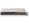
Dell M8428-k 10 Gb Converged Network Switch The Dell M8428-k 10 Gb Converged Network switch module supports FCoE protocols and allows Fibre Channel traffic to travel over 10 Gbps Enhanced Ethernet (DCB) networks. This module consists of: • Four 8 Gbps external autosensing Fibre Channel ports. • - Dell PowerConnect M8428-k | Dell
PowerEdge M1000e Configuration Guide - Page 56
3-5. Dell M8428-k 10 Gb Converged Network Switch 7 1 2 6 3 5 4 1 LED status indicators (12) 3 module status indicator 5 power indicator 7 10 GbEE ports (ports 17-24) 2 serial port (RJ-45 connector) 4 status indicator 6 8 Gb Fibre Channel ports (ports 25-27 and port 0) 56 Configuring the - Dell PowerConnect M8428-k | Dell
PowerEdge M1000e Configuration Guide - Page 57
connectivity to the blades in the enclosure. Figure 3-6. Mellanox M2401G Infiniband Switch Module 1 2 3 4 5 1 Infiniband ports (8) 3 port activity indicators (8) 5 module status indicator 2 port link status indicators (8) 4 module diagnostic power indicator Configuring the I/O Modules 57 - Dell PowerConnect M8428-k | Dell
PowerEdge M1000e Configuration Guide - Page 58
enclosure. This module occupies two I/O module slots. By default, the M3610Q module plugs into I/O module slot C1, but occupies both slots B1 and C1. It can also be plugged into I/O module slot B1 (occupying slots A1 and B1) or slot B2 (occupying slots B2 and C2). 58 Configuring the I/O Modules - Dell PowerConnect M8428-k | Dell
PowerEdge M1000e Configuration Guide - Page 59
Figure 3-7. Mellanox M3601Q Infiniband Switch Module 1 2 3 4 5 1 Infiniband ports (16) 3 port activity indicators (16) 5 module status indicator 2 port link status indicators (16) 4 module diagnostic power indicator Configuring the I/O Modules 59 - Dell PowerConnect M8428-k | Dell
PowerEdge M1000e Configuration Guide - Page 60
enclosure. This switch module is hot-swappable, and may be installed in Fabric B or Fabric C. Figure 3-8. Cisco SFS M7000e Infiniband Switch Module Features 1 2 3 4 1 Infiniband ports (8) 3 diagnostic status indicator 2 port status indicator (8) 4 power indicator 60 Configuring the I/O Modules - Dell PowerConnect M8428-k | Dell
PowerEdge M1000e Configuration Guide - Page 61
Mb Ethernet uplink ports, two 10 Gb uplink ports, and two Stackwise Plus ports. • The Cisco CBS 3032 switch includes four 10/100/1000 Mb Ethernet uplink ports. The two option bays support the following module options: • Cisco X2 10 Gb transceiver modules (CBS 3130X-S only) • Cisco TwinGig converter - Dell PowerConnect M8428-k | Dell
PowerEdge M1000e Configuration Guide - Page 62
Switch Module Features 1 2 3 4 5 6 7 8 1 Stackwise Plus connectors (not enabled in CBS 3032) 3 option bays (2) 5 mode button 7 power indicator 2 10/100/1000 Mb Ethernet connectors (4) 4 Cisco status indicators 6 console port for switch management 8 status/identification indicator 62 Configuring - Dell PowerConnect M8428-k | Dell
PowerEdge M1000e Configuration Guide - Page 63
provides additional stacking and redundancy support. Sixteen internal Gb Ethernet connectors link to the blades in the enclosure. For additional information about the PowerConnect M6220 Ethernet switch module, see the documentation that shipped with the module. Configuring the I/O Modules 63 - Dell PowerConnect M8428-k | Dell
PowerEdge M1000e Configuration Guide - Page 64
10. PowerConnect M6220 Ethernet Switch Module Features 1 2 3 4 5 1 optional module (2) (dual 10 Gb Ethernet uplink module shown) 2 standard 10/100/1000 Mb Ethernet connectors (4) 3 serial connector (USB type-A form 4 power indicator factor) 5 status/identification indicator 64 Configuring the - Dell PowerConnect M8428-k | Dell
PowerEdge M1000e Configuration Guide - Page 65
, the remaining 32 internal ports provide connectivity to the blades within the enclosure with a maximum bandwidth of 1 Gbps each. The PowerConnect M6348 switch also supports: • Two integrated 10 Gb Ethernet SFP+ connectors • Two integrated CX4 connectors for stacking or 10 Gb uplinks • One console - Dell PowerConnect M8428-k | Dell
PowerEdge M1000e Configuration Guide - Page 66
Figure 3-11. PowerConnect M6348 Switch Module 1 2 3 4 5 6 1 standard 10/100/1000 Mb Ethernet connectors (16) 3 CX4 stacking connectors (2) 5 power indicator 2 SFP+ connectors (2) 4 console management connector 6 status/identification indicator 66 Configuring the I/O Modules - Dell PowerConnect M8428-k | Dell
PowerEdge M1000e Configuration Guide - Page 67
and the connect switch-n CMC CLI command. For more information, see the CMC User's Guide. Once an IP address is assigned to the management VLAN or interface and the switch is connected to a management network, both Telnet and http are available through the network. Configuring the I/O Modules 67 - Dell PowerConnect M8428-k | Dell
PowerEdge M1000e Configuration Guide - Page 68
Figure 3-12. PowerConnect M8024 Switch Module 1 2 3 4 5 1 optional module with four SFP+ ports 2 optional module with three CX4 ports 3 serial connector for optional USB 4 power indicator type-A form-factor cable 5 status/identification indicator 68 Configuring the I/O Modules - Dell PowerConnect M8428-k | Dell
PowerEdge M1000e Configuration Guide - Page 69
M4424 SAN I/O Module The Brocade M4424 SAN I/O module includes eight external autosensing Fibre Channel ports (four ports are enabled in the standard configuration and four additional ports may be enabled as an optional upgrade), 16 internal ports, and one serial port with an RJ-45 connector. The - Dell PowerConnect M8428-k | Dell
PowerEdge M1000e Configuration Guide - Page 70
Figure 3-13. Brocade M4424 SAN I/O Module 1 2 3 4 5 6 1 Fibre Channel port (8) 3 Fibre Channel port speed indicator (8) 5 module status indicator 7 status/identification indicator 7 2 Fibre Channel port status indicator (8) 4 serial port (RJ-45 connector) 6 power indicator 70 Configuring the - Dell PowerConnect M8428-k | Dell
PowerEdge M1000e Configuration Guide - Page 71
sec. NOTE: CMC firmware version 1.3 is required to support FC8 mezzanine cards and I/O modules. NOTE: This Fibre Channel switch module includes Short Wave Small Form Factor Pluggable (SFP) optical transceivers. To ensure proper functionality, use only SFPs provided with this module. Configuring the - Dell PowerConnect M8428-k | Dell
PowerEdge M1000e Configuration Guide - Page 72
Figure 3-14. Brocade M5424 FC8 I/O Module 1 2 3 4 5 6 1 Fibre Channel port (8) 3 Fibre Channel port speed indicator (8) 5 module status indicator 7 status/identification indicator 7 2 Fibre Channel port status indicator (8) 4 serial port (RJ-45 connector) 6 power indicator 72 Configuring the - Dell PowerConnect M8428-k | Dell
PowerEdge M1000e Configuration Guide - Page 73
sec. NOTE: CMC firmware version 1.3 is required to support FC8 mezzanine cards and I/O modules. NOTE: This Fibre Channel switch module includes Short Wave Small Form Factor Pluggable (SFP) optical transceivers. To ensure proper functionality, use only SFPs provided with this module. Configuring the - Dell PowerConnect M8428-k | Dell
PowerEdge M1000e Configuration Guide - Page 74
Figure 3-15. Dell 8/4 Gbps FC SAN Module 1 2 3 4 5 6 1 Fibre Channel port (8) 3 Fibre Channel port speed indicator (8) 5 module status indicator 7 status/identification indicator 7 2 Fibre Channel port status indicator (8) 4 serial port (RJ-45 connector) 6 power indicator 74 Configuring the - Dell PowerConnect M8428-k | Dell
PowerEdge M1000e Configuration Guide - Page 75
Dell 10 GbE KR Pass-Through I/O Module The 10 GbE KR pass-through module supports 10 Gb connections and provides a direct connection between the optional internal Ethernet KR mezzanine card or KR network not support 1G mezzanine or network daughter cards in blades. Configuring the I/O Modules 75 - Dell PowerConnect M8428-k | Dell
PowerEdge M1000e Configuration Guide - Page 76
Figure 3-16. Dell 10 GbE KR Pass-Through I/O Module 1 2 4 3 1 SFP+ ports (16) 3 status/identification indicator 2 green/amber indicators (two per port) 4 power indicator 76 Configuring the I/O Modules - Dell PowerConnect M8428-k | Dell
PowerEdge M1000e Configuration Guide - Page 77
Dell 8/4 Gbps Fibre Channel Pass-Through I/O Module The 8G Fibre Channel pass-through module provides a bypass connection between a Fibre Channel mezzanine card in the blade and optical transceivers. The bypass connection enables a direct connection to a Fibre Channel switch or a storage array. The - Dell PowerConnect M8428-k | Dell
PowerEdge M1000e Configuration Guide - Page 78
Figure 3-17. Dell 8/4 Gbps Fibre Channel Pass-Through I/O Module 1 2 4 3 1 Fibre Channel ports (16) 3 status/identification indicator 2 port status indicators 4 power indicator 78 Configuring the I/O Modules - Dell PowerConnect M8428-k | Dell
PowerEdge M1000e Configuration Guide - Page 79
10 Gb Ethernet Pass-Through Module II The Dell 10 Gb Ethernet pass-through module II supports 10 Gb connections and provides a direct connection between ) SFP+ modules. The Ethernet pass-through module does not support 1G mezzanine or network daughter cards in blades. Configuring the I/O Modules 79 - Dell PowerConnect M8428-k | Dell
PowerEdge M1000e Configuration Guide - Page 80
Figure 3-18. 10 Gb Ethernet Pass-Through Module II 1 2 3 1 SFP+ cages (16) 3 status/identification indicator 4 2 green/amber indicators (two per port) 4 power indicator 80 Configuring the I/O Modules - Dell PowerConnect M8428-k | Dell
PowerEdge M1000e Configuration Guide - Page 81
Pass-Through I/O Module The 10 Gb Ethernet pass-through module supports 10 Gb connections and provides a direct connection between the optional multimode (LRM), or DCA SFP+ modules. This module does not support 1G mezzanine or network daughter cards in blades. Configuring the I/O Modules 81 - Dell PowerConnect M8428-k | Dell
PowerEdge M1000e Configuration Guide - Page 82
Figure 3-19. 10 Gb Ethernet Pass-Through I/O Module 1 2 1 SFP+ cages (16) 3 power indicator 3 4 2 green/amber indicators (two per port) 4 status/identification indicator 82 Configuring the I/O Modules - Dell PowerConnect M8428-k | Dell
PowerEdge M1000e Configuration Guide - Page 83
module supports 10/100/1000 Mb connections and provides a direct connection between the optional internal Ethernet mezzanine card in the blade and an external Ethernet device. The Ethernet pass-through modules are hot-swappable and may be installed in any of the three Fabrics. Configuring the - Dell PowerConnect M8428-k | Dell
PowerEdge M1000e Configuration Guide - Page 84
on the Ethernet pass-through module correspond directly to the blade number. For example, blade 5 is connected to port 5 on the Ethernet passthrough module. Integrated network adapter 1 maps to I/O slot A1. Integrated network adapter 2 maps to I/O slot A2. 84 Configuring the I/O Modules - Dell PowerConnect M8428-k | Dell
PowerEdge M1000e Configuration Guide - Page 85
the blade and optical transceivers. The bypass connection enables a direct connection to a Fibre Channel switch or a storage array. The 16 pass-through ports on this module can negotiate speeds of Form Factor Pluggable (SFP) transceivers provided with this module. Configuring the I/O Modules 85 - Dell PowerConnect M8428-k | Dell
PowerEdge M1000e Configuration Guide - Page 86
Figure 3-21. 4G Fibre Channel Pass-Through Module 1 2 3 4 1 SFP Fibre Channel connector (16) 2 Fibre Channel green/amber indicators (two per port) 3 power indicator 4 status/identification indicator 86 Configuring the I/O Modules
-
 1
1 -
 2
2 -
 3
3 -
 4
4 -
 5
5 -
 6
6 -
 7
7 -
8
-
9
-
10
-
11
-
12
-
13
-
14
-
15
-
16
-
17
-
18
-
19
-
20
-
21
-
22
-
23
-
24
-
25
-
26
-
27
-
28
-
29
-
30
-
31
-
32
-
33
-
34
-
35
-
36
-
37
-
38
-
39
-
40
-
41
-
42
-
43
-
44
-
45
-
46
-
47
-
48
-
49
-
50
-
51
-
52
-
53
-
54
-
55
-
56
-
57
-
58
-
59
-
60
-
61
-
62
-
63
-
64
-
65
-
66
-
67
-
68
-
69
-
70
-
71
-
72
-
73
-
74
-
75
-
76
-
77
-
78
-
79
-
80
-
81
-
82
-
83
-
84
-
85
-
86
 |
 |

Dell PowerEdge M1000e
Systems
Configuration Guide