Dell PowerConnect W-IAP108 W-IAP108/109 Installation Guide
Dell PowerConnect W-IAP108 Manual
 |
View all Dell PowerConnect W-IAP108 manuals
Add to My Manuals
Save this manual to your list of manuals |
Dell PowerConnect W-IAP108 manual content summary:
- Dell PowerConnect W-IAP108 | W-IAP108/109 Installation Guide - Page 1
while simultaneously supporting existing 802.11a/b/g wireless services. The W-IAP108 admin. See the included Dell Instant Quick Start Guide for more information. 4. Navigate to the Maintenance . RAP Conversion If your network administrator has instructed you to convert the W-IAP108/WIAP109 to work - Dell PowerConnect W-IAP108 | W-IAP108/109 Installation Guide - Page 2
accordance with the manufacturer's instructions may cause harmful interference to Consult the manufacturer or field service technician for help. The Models Guide Contacting Support Web Site Support Main Site Support Site Dell Documentation dell.com dell.com /support dell.com /support/manuals
-
 1
1 -
 2
2
 |
 |
Dell PowerConnect W-IAP108/109 Instant Access Point
Installation Guide
The Dell PowerConnect W-IAP108 and W-IAP109 are dual-radio, dual-band remote
access points that support the IEEE 802.11n standard for high-performance WLAN.
These access points use MIMO (Multiple-in, Multiple-out) technology and other
high-throughput mode techniques to deliver high-performance, 802.11n 2.4 GHz
and 5 GHz functionality while simultaneously supporting existing 802.11a/b/g
wireless services.
The W-IAP108/W-IAP109 ship with Dell Instant software. Therefore, out of the box,
the W-IAP108/W-IAP109 will operate as a Virtual Controller (VC) or an Instant AP.
However, the W-IAP108/W-IAP109 can be converted to operate as a Remote AP
(RAP). For information about the IAP to RAP conversion, see
RAP Conversion
.
The Dell W-IAP108/W-IAP109 remote access point provides the following
capabilities:
Wireless transceiver
Protocol-independent networking functionality
IEEE 802.11a/b/g/n operation as a wireless access point
IEEE 802.11a/b/g/n operation as a wireless air monitor
Compatibility with IEEE 802.3af and 802.3at
Package Contents
W-IAP108 or W-IAP109 Remote Access Point
W-IAP108/W-IAP109 Mounting Stand
Installation Guide
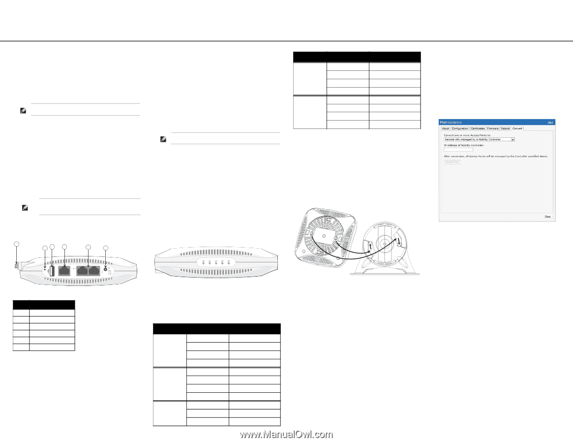
W-IAP108/W-IAP109 Hardware Overview
Figure 1
Ports and Connectors
External Antenna Connectors (W-IAP108 Only)
The W-IAP108 is equipped with two RP-SMA external antenna connectors and
requires the use of two dual-band antennas. These ports are marked ANT0 and
ANT1, matching radio chains 0 and 1.
In order to ensure accurate RF power level setting and reporting in software, as well
as compliance with any regulatory restrictions, the correct gain for antennas used
(adjusted for any additional cabling loss, if applicable) needs to be entered in
software when provisioning the W-IAP108. Two antenna gain numbers are needed
for this; one for each supported band (2.4GHz and 5GHz). These numbers can be
obtained from the antenna datasheet or specifications. Antenna gain for W-IAP109
is hardcoded to the correct values already, so there is no need for any additional
action on that platform.
Reset Button
The reset button can be used to return the AP to factory default settings. To reset
the AP:
1.
Power off the AP.
2.
Press and hold the reset button using a small, narrow object, such as a paperclip.
3.
Power-on the AP without releasing the reset button. The power LED will flash
within 5 seconds.
4.
Release the reset button.
The power LED will flash again within 15 seconds indicating that the reset is
completed. The AP will now continue to boot with the factory default settings.
USB Interface
The W-IAP108/W-IAP109 is equipped with a USB interface for connectivity with
cellular modems.
Console Port
Use the console port to connect to a terminal for direct local management.
ENET 0
For primary network connectivity, W-IAP108/W-IAP109 is equipped with a 10/100/
1000BASE-T (RJ-45) auto-sensing, MDI/MDX Gigabit Ethernet port. This port
supports IEEE 802.3af Power over Ethernet (PoE) compliance, accepting 48VDC as
a standard defined Powered Device (PD) from a Power Sourcing Equipment (PSE)
such as a PoE midspan injector, or network infrastructure that supports PoE.
ENET 1
For secondary network connectivity, W-IAP108/W-IAP109 is equipped with a 10/
100BASE-T (RJ-45) auto-sensing, MDI/MDX Fast Ethernet port.
DC Power Socket
If PoE is not available, an optional AC-DC adapter kit (sold separately) can be used
to power the W-IAP108/W-IAP109.
Figure 2
LEDs
LEDs
PWR: Indicates whether or not the W-IAP108/W-IAP109 is powered-on
ENET0 and ENET1: Indicates the status of the W-IAP108/W-IAP109’s Ethernet
ports
5 GHz: Indicates the status of the 802.11a/n radio
2.4 GHz: Indicates the status of the 802.11b/g/n radio
Installing the AP
Tabletop Mounting
The W-IAP108/W-IAP109 is shipped with a stand to use on flat (i.e. table top)
surfaces. Place the W-IAP108/W-IAP109 in the stand (see
Figure 3
) and place the
stand on a flat, level surface.
To attach the IAP to the stand:
1.
Align the center peg of the stand with recessed hole on the unit.
2.
Align the mounting posts on the back of the AP with corresponding openings on
the stand.
3.
Rotate the AP clockwise until it clicks into place.
Figure 3
Stand Installation
Connecting the Required Cables
The W-IAP108/W-IAP109 must be connected to a network device that has access to
the Internet, such as a router or modem. To complete the installation of the W-
IAP108/W-IAP109:
1.
Connect one end of the provided RJ-45 cable to port E0 on the W-IAP108/W-
IAP109.
2.
Connect the other end of the RJ-45 cable to a free RJ-45 port on your modem or
router.
3.
Attach the provided power adapter to the DC IN port on the W-IAP108/W-
IAP109.
4.
Connect the other end of the power adapter to a power outlet.
The W-IAP108/W-IAP109 is now powered on. To verify this, ensure that the PWR
LED is solid green.
Verifying Successful Installation
Once the W-IAP108/W-IAP109’s PWR LED has come up, the device will take 2 to 3
minutes to complete the boot cycle. Once the boot cycle is complete, you can
connect to your company or corporate network.
RAP Conversion
If your network administrator has instructed you to convert the W-IAP108/W-
IAP109 to work in RAP mode, follow the process below to complete the RAP
conversion.
1.
Power up the W-IAP108/W-IAP109.
2.
Connect to Instant SSID.
3.
Login to the W-IAP108/W-IAP109 by navigating to
and login to the Instant
WebUI. The default username is admin and the default password is admin. See
the included
Dell Instant Quick Start Guide
for more information.
4.
Navigate to the Maintenance tab in the top right.
5.
Click on the Convert tab.
6.
Select Remote APs managed by a Mobility Controller from the drop down
menu.
7.
Enter the IP address of the controller. This is provided by your network
administrator.
8.
Click Convert Now to complete the conversion (see
Figure 4
).
9.
The W-IAP108/W-IAP109 will reboot and begin operating in RAP mode.
Figure 4
IAP-RAP Conversion over the Internet
Note:
The W-IAP108/W-IAP109 requires the use of Instant 3.2. To convert the IAPs
to a RAP, a controller running ArubaOS 6.2 is required.
Note:
Inform your supplier if there are any incorrect, missing, or damaged
parts. If possible, retain the carton, including the original packing materials.
Use these materials to repack and return the unit to the supplier if needed.
Table 1
Ports and Connectors
Callout
Component
1
External Antenna Connector
2
Reset Button
3
USB Interface
4
Console Port
5
ENET 0 and ENET 1
6
DC Power Socket
ENET 1
ENET 0
56V
350mA
1.25A
CONSOLE
1
2
3
4
5
6
Note:
The USB interface is disabled when the W-IAP108/W-IAP109 is powered
from 802.3af PoE.
LED
Color/State
Meaning
PWR
Off
No power to AP
Red steady
System initializing
Green flashing
Device booting, not ready
Green steady
Device ready
ENET0
Off
No link
Amber
10/100 Mbps link
Green
1000 Mbps link
Flashing
Ethernet link activity
ENET1
Off
No link
Green
10/100 Mbps link
Flashing
Ethernet link activity
2.4 GHz
5 GHz
ENET 1
ENET 0
PWR
5 GHz
Off
5 GHz radio is disabled
Amber steady
5 GHz radio enabled in WLAN mode
Green steady
5 GHz radio enabled in 11n mode
Green flashing
5 GHz Air Monitor mode
2.4 GHz
Off
2.4 GHz radio disabled
Amber steady
2.4 GHz radio enabled in WLAN mode
Green steady
2.4 GHz radio enabled in 11n mode
Green flashing
2.4 GHz Air Monitor mode
LED
Color/State
Meaning