Dell PowerEdge M905 Dell PowerEdge M1000e Configuration Guide
Dell PowerEdge M905 Manual
 |
View all Dell PowerEdge M905 manuals
Add to My Manuals
Save this manual to your list of manuals |
Dell PowerEdge M905 manual content summary:
- Dell PowerEdge M905 | Dell
PowerEdge M1000e Configuration Guide - Page 1
Dell PowerEdge M1000e Systems Configuration Guide - Dell PowerEdge M905 | Dell
PowerEdge M1000e Configuration Guide - Page 2
CAUTION indicates potential damage to hardware or loss of data if instructions are not followed. WARNING: A WARNING indicates a potential for Dell Inc. is strictly forbidden. Trademarks used in this text: Dell™, the DELL logo, PowerEdge™, PowerConnect™, and FlexAddress™ are trademarks of Dell - Dell PowerEdge M905 | Dell
PowerEdge M1000e Configuration Guide - Page 3
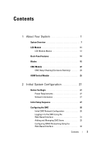
7 LCD Module 11 LCD Module Menus 12 Back-Panel Features 14 Blades 15 CMC Module 22 CMC Daisy Chaining (Enclosure Stacking) . . . . 23 iKVM Switch Module 25 2 Initial System Configuration 27 Before You Begin 27 Power Requirements 27 Network Information 27 Initial Setup Sequence 27 - Dell PowerEdge M905 | Dell
PowerEdge M1000e Configuration Guide - Page 4
the First Boot Device for Servers . . . . . 34 Configuring and Managing Power 35 Installing or Updating the CMC Firmware . . . . . 35 Configuring the Optional iKVM Switch Module . . . . 38 Enabling iKVM Access to the Dell CMC Console 38 Updating the iKVM Firmware 38 Tiering the Avocent iKVM - Dell PowerEdge M905 | Dell
PowerEdge M1000e Configuration Guide - Page 5
Ethernet Switch I/O Module 67 Brocade M4424 SAN I/O Module 69 Brocade M5424 FC8 I/O Module 71 Dell 8/4 Gbps FC SAN Module 73 Pass-Through Modules 75 Dell 10 GbE KR Pass-Through I/O Module . . . . . 75 Dell 8/4 Gbps Fibre Channel Pass-Through I/O Module 77 10 Gb Ethernet Pass-Through Module II - Dell PowerEdge M905 | Dell
PowerEdge M1000e Configuration Guide - Page 6
6 Contents - Dell PowerEdge M905 | Dell
PowerEdge M1000e Configuration Guide - Page 7
-height blades (server modules), eight full-height blades, or a mixture of the two blade types (see Figure 1-1, Figure 1-2, and Figure 1-3). To function as a system, a blade is inserted into a Dell PowerEdge M1000e enclosure (chassis) that supports power supplies, fan modules, a Chassis Management - Dell PowerEdge M905 | Dell
PowerEdge M1000e Configuration Guide - Page 8
Figure 1-1. Blade Numbering-Half-Height Blades 1 2 3 4 56 7 8 9 10 11 12 13 14 15 16 8 About Your System - Dell PowerEdge M905 | Dell
PowerEdge M1000e Configuration Guide - Page 9
Figure 1-2. Blade Numbering-Full Height Blades 1 2 3 4 56 7 8 Figure 1-3. Blade Numbering-Mixed Full-Height and Half-Height Blades 1 2 3 4 56 7 8 13 14 15 16 About Your System 9 - Dell PowerEdge M905 | Dell
PowerEdge M1000e Configuration Guide - Page 10
M1000e enclosure panel. Figure 1-4. Control Panel Features 2 3 1 4 5 1 USB port (mouse only) 2 USB port (keyboard only) 3 video connector 4 system power button 5 system power indicator NOTE: The USB and video ports are functional only if an optional iKVM module is installed. 10 About - Dell PowerEdge M905 | Dell
PowerEdge M1000e Configuration Guide - Page 11
LCD Module The LCD module provides an initial configuration/deployment wizard, as well as access to infrastructure and blade information, and error reporting. See Figure 1-5. Figure 1-5. LCD Module 3 2 1 1 LCD screen 3 selection ("check") button 2 scroll buttons (4) About Your System 11 - Dell PowerEdge M905 | Dell
PowerEdge M1000e Configuration Guide - Page 12
default language and start-up screen for the LCD menu screens using this menu. Server Menu From the Server Menu dialog box, you can highlight each blade in the enclosure using the arrow keys, and view its status. • A blade that is powered off or booting is designated by a gray rectangle. An active - Dell PowerEdge M905 | Dell
PowerEdge M1000e Configuration Guide - Page 13
any errors present. • In the Enclosure Status dialog box, you can view the enclosure status, any error conditions, and power consumption statistics. • The Network Summary screen lists the IP addresses for the CMC, the iDRAC in each blade, and other components in the enclosure. About Your System 13 - Dell PowerEdge M905 | Dell
PowerEdge M1000e Configuration Guide - Page 14
Back-Panel Features The back panel of the M1000e enclosure supports six I/O modules, one or two CMC modules, an optional iKVM module, nine fan modules, and six power supply modules. Figure 1-6 shows a fully configured enclosure. Figure 1-6. Back Panel Features 1 2 3 4 5 6 1 fan modules (9) 3 - Dell PowerEdge M905 | Dell
PowerEdge M1000e Configuration Guide - Page 15
Blades Figure 1-7. Front Panel Features-PowerEdge M910 1 2 6 5 4 3 1 blade-handle release button 2 hard drives (2) 3 blade status/identification indicator 4 USB connectors (3) 5 blade power button 6 blade power indicator About Your System 15 - Dell PowerEdge M905 | Dell
PowerEdge M1000e Configuration Guide - Page 16
Figure 1-8. Front Panel Features-PowerEdge M905 and M805 1 2 6 5 4 3 1 blade handle release button 2 hard drives (2) 3 blade status/identification indicator 4 USB connectors (3) 5 blade power button 6 blade power indicator 16 About Your System - Dell PowerEdge M905 | Dell
PowerEdge M1000e Configuration Guide - Page 17
Figure 1-9. Front Panel Features-PowerEdge M710HD 1 6 5 4 2 3 1 blade power indicator 3 hard drives (2) 5 USB connectors (2) 2 blade handle release button 4 blade status/identification indicator 6 blade power button About Your System 17 - Dell PowerEdge M905 | Dell
PowerEdge M1000e Configuration Guide - Page 18
Figure 1-10. Front Panel Features-PowerEdge M710 1 2 6 5 4 3 1 blade handle release button 3 USB connectors (3) 5 blade power button 2 hard drives (4) 4 blade status/identification indicator 6 blade power indicator 18 About Your System - Dell PowerEdge M905 | Dell
PowerEdge M1000e Configuration Guide - Page 19
-PowerEdge M610x 1 8 7 6 2 5 3 4 1 blade handle release button 2 hard drives (2) 3 expansion-card filler-bracket 4 expansion-card slots (2) retention latch with captive screw 5 blade status/identification indicator 6 USB connectors (2) 7 blade power button 8 blade power indicator - Dell PowerEdge M905 | Dell
PowerEdge M1000e Configuration Guide - Page 20
Figure 1-12. Front Panel Features-PowerEdge M610 1 6 5 4 3 2 1 blade handle release button 2 hard drives (2) 3 blade status/identification indicator 4 USB connectors (2) 5 blade power button 6 blade power indicator 20 About Your System - Dell PowerEdge M905 | Dell
PowerEdge M1000e Configuration Guide - Page 21
Figure 1-13. Front Panel Features-PowerEdge M600 and M605 1 2 6 5 4 3 1 blade handle release button 2 hard drives (2) 3 blade status/identification indicator 4 USB connectors (2) 5 blade power button 6 blade power indicator About Your System 21 - Dell PowerEdge M905 | Dell
PowerEdge M1000e Configuration Guide - Page 22
connector Gb1 3 link indicator (2) 5 DB-9 serial connector for local configuration 7 primary CMC (CMC 1) 9 status/identification indicator 2 Ethernet connector fault indicator 10 power indicator The CMC provides multiple systems management functions for your modular server, including the M1000e - Dell PowerEdge M905 | Dell
PowerEdge M1000e Configuration Guide - Page 23
daisy chaining can be utilized to minimize the number of network connections required for chassis (enclosure) management, such that only one or In a non-redundant CMC, cable all CMC modules in the CMC primary slots together. Figure 1-15 shows four enclosures with redundant CMC modules installed. - Dell PowerEdge M905 | Dell
PowerEdge M1000e Configuration Guide - Page 24
Figure 1-15. CMC Daisy Chaining-Enclosure With Redundant CMC Modules 1 2 3 1 management network segment 2 CMC1-cable from connector Gb1 to network 3 CMC2-cable from connector Gb1 to network 24 About Your System - Dell PowerEdge M905 | Dell
PowerEdge M1000e Configuration Guide - Page 25
session to a given blade is available to both the iDRAC interface and an iKVM (user connected to a blade's console through iDRAC and NOTE: The iKVM USB ports do not support storage devices. - RJ-45 ACI port for tiering with Dell and Avocent analog KVM and KVM over Guide. About Your System 25 - Dell PowerEdge M905 | Dell
PowerEdge M1000e Configuration Guide - Page 26
Figure 1-16 shows the external features of the iKVM module. Figure 1-16. Avocent iKVM Switch Module 2 3 4 5 1 1 identification indicator 2 status indicator 3 ACI port for tiering connection 4 USB connectors (2) for keyboard only and mouse 5 video connector CAUTION: Do not connect the - Dell PowerEdge M905 | Dell
PowerEdge M1000e Configuration Guide - Page 27
information, see the Getting Started Guide and Rack Installation Guide at support.dell.com/manuals. CAUTION: Do not turn on the blades (server modules) until you have configured the switch modules, as described in "Configuring the I/O Modules" on page 47. 2 Connect the power supply units to a PDU - Dell PowerEdge M905 | Dell
PowerEdge M1000e Configuration Guide - Page 28
"Configuring the I/O Modules" on page 47. 7 Once the Ethernet and Fibre Channel switches are configured, you can power on your server blades. address of your choice. For initial configuration instructions, see "Configuring the CMC Network Settings Using the LCD Configuration Wizard" on page 28. To - Dell PowerEdge M905 | Dell
PowerEdge M1000e Configuration Guide - Page 29
. You can access the CLI using the 17th Blade feature on the embedded iKVM module. Blade number 17 is a direct local connection to the CMC. 1 Choose a language from the options presented in the dialog box. 2 Start the LCD Configuration Wizard. 3 Configure the CMC network settings for your network - Dell PowerEdge M905 | Dell
PowerEdge M1000e Configuration Guide - Page 30
. Press and select blade number 17. • Serial connection using an optional null modem cable (115200 bps, 8 data bits, no parity, 1 stop bit, and no flow control). Once you have established a connection to the CMC, you can complete the initial CMC network configuration: 1 Log in to the - Dell PowerEdge M905 | Dell
PowerEdge M1000e Configuration Guide - Page 31
in a few seconds after configuring the network. Logging in to the CMC Using the Web-Based Interface 1 Open a supported Web browser window. For more information, see "Supported Web Browsers" in the CMC User's Guide. 2 Log in to the CMC. - If the CMC is accessed using a specific IP address, type the - Dell PowerEdge M905 | Dell
PowerEdge M1000e Configuration Guide - Page 32
setup. NOTE: The CMC does not support extended ASCII characters, such as or other or as Directory Service user in Microsoft Active Directory or Lightweight Directory Access Protocol Services (LDAP). Managing CMC Users From the Users and User Configuration pages in the Web-based interface, you - Dell PowerEdge M905 | Dell
PowerEdge M1000e Configuration Guide - Page 33
-Based Interface" on page 31. 2 Select Chassis in the system tree. 3 Click the Network configuration have no user information displayed. 4 Click an available user ID number. The User Configuration groups and privileges, see "Adding and Configuring Users" in the CMC User's Guide. 6 Assign the user to a - Dell PowerEdge M905 | Dell
PowerEdge M1000e Configuration Guide - Page 34
for each blade. You can set the default boot device and you can also set a one-time boot device so that you can boot a special image to perform tasks such as running diagnostics or reinstalling an operating system. To set the first boot device for some or all servers in the chassis: 1 Log - Dell PowerEdge M905 | Dell
PowerEdge M1000e Configuration Guide - Page 35
For detailed information on the various power management options, see "Power Management" in the CMC User's Guide. Configuring Power Budget and Redundancy The CMC's power management service optimizes power consumption for the entire chassis (the chassis, servers, I/O modules, iKVM, CMC, and PSUs) and - Dell PowerEdge M905 | Dell
PowerEdge M1000e Configuration Guide - Page 36
revision, use the cmcchangeover command to reset the CMC in the left slot as primary. Downloading the CMC Firmware Before beginning the firmware update, download the latest firmware version from support.dell.com, and save it to your local system. The following software components are included - Dell PowerEdge M905 | Dell
PowerEdge M1000e Configuration Guide - Page 37
console and log in. 2 Type: racadm fwupdate -g -u -a -d -m See the latest Dell Chassis Management Controller User's Guide at support.dell.com/manuals for complete instructions on how to configure and operate the CMC module. Initial System - Dell PowerEdge M905 | Dell
PowerEdge M1000e Configuration Guide - Page 38
Configuring the Optional iKVM Switch Module Enabling iKVM Access to the Dell CMC Console Enabling access to " on page 31. 2 Select Chassis in the system tree. 3 Click the Update tab. The Updatable Components page is displayed. 4 Click the iKVM name. The Firmware Update page is displayed. 5 In the - Dell PowerEdge M905 | Dell
PowerEdge M1000e Configuration Guide - Page 39
dialog box is displayed. 3 Select Slot to display servers numerically by slot number. 4 Enter a screen delay time configure the analog switch: 1 Press to open the OSCAR Main dialog box. 2 Click Setup Devices Device Modify. 3 Select the 16-port option to match the number of blades - Dell PowerEdge M905 | Dell
PowerEdge M1000e Configuration Guide - Page 40
slot number of the blade to which the iKVM switch is now attached should be expanded to display each of the slot locations of the blades the other end of this cable to powered up before the system, it may result in only one blade of blades is blades Dell 2161DS-2 or 4161DS, or a supported - Dell PowerEdge M905 | Dell
PowerEdge M1000e Configuration Guide - Page 41
view, configure, and manage servers in the M1000e enclosure through the iKVM. You can view the servers by name or by slot. The slot number is the chassis slot number the server occupies. The Slot column indicates the slot number in which a server is installed. NOTE: Server names and slot numbers are - Dell PowerEdge M905 | Dell
PowerEdge M1000e Configuration Guide - Page 42
ensure consistency. To resynchronize the server listing: 1 Click Resync in the Server category of the Management Panel (MP). The Resync Wizard launches. 2 Click Next. A warning message appears indicating that the database will be updated to match the current configuration of the console switch. Your - Dell PowerEdge M905 | Dell
PowerEdge M1000e Configuration Guide - Page 43
module. If a server module is moved to a chassis that does not support FlexAddress, the factory assigned WWN/MAC IDs are used. Prior to installing FlexAddress, you can determine the range of MAC addresses contained on a FlexAddress feature card by inserting the SD card into an USB Memory Card Reader - Dell PowerEdge M905 | Dell
PowerEdge M1000e Configuration Guide - Page 44
2.72A2 or M4 later Server Module BIOS (PowerEdge M600) BIOS 2.02 or later (PowerEdge M605) BIOS 2.03 or later PowerEdge M600/M605 LAN on motherboard (LOM) Boot code firmware 4.4.1 or later iSCSI boot firmware 2.7.11 or later iDRAC Version 1.11 or later 44 Initial System Configuration - Dell PowerEdge M905 | Dell
PowerEdge M1000e Configuration Guide - Page 45
Plus. Component Server Module BIOS iDRAC CMC Minimum required version PowerEdge M710HD Version 3.0 or later Version 3.0 or later For more information on the FlexAddress feature, see the following resources: • The CMC Secure Digital (SD) Card Technical Specification document at support.dell.com - Dell PowerEdge M905 | Dell
PowerEdge M1000e Configuration Guide - Page 46
46 Initial System Configuration - Dell PowerEdge M905 | Dell
PowerEdge M1000e Configuration Guide - Page 47
Infiniband switches, Ethernet switches, and Ethernet passthrough modules. Figure 3-1 shows the numbering of the I/O bays and other back-panel features. Figure 3-1. I/O Module Bay Numbering CMC 1 A1 B1 C1 iKVM C2 B2 A2 CMC 2 1 2 3 4 5 6 7 8 9 12 3 4 5 6 Configuring the I/O Modules 47 - Dell PowerEdge M905 | Dell
PowerEdge M1000e Configuration Guide - Page 48
specifically for Fabric B or Fabric C cannot be installed in slots A1 or A2, as indicated by the color-coded label on the faceplate of each module. Fabric B Fabric B is a 1 to 40 Gb/sec redundant fabric, supporting I/O module slots module in the Fabric B slots, a blade must have a matching mezzanine - Dell PowerEdge M905 | Dell
PowerEdge M1000e Configuration Guide - Page 49
Owner's Manual. Identifying Midplane slots A1, A2 Midplane Version 1.1 I/O module slots B1, B2, C1, 1.1 and C2 I/O module slots A1, A2 1.0 I/O module slots B1, B2, C1, 1.0 and C2 See Figure 3-2 and Figure 3-3 to locate the midplane identification labels on the enclosure. Configuring - Dell PowerEdge M905 | Dell
PowerEdge M1000e Configuration Guide - Page 50
Figure 3-2. Identifying Midplane Version 1.1 1 1 midplane identification labels (2) 50 Configuring the I/O Modules - Dell PowerEdge M905 | Dell
PowerEdge M1000e Configuration Guide - Page 51
Figure 3-3. Identifying Midplane Version 1.0 1 1 midplane identification labels (2) Configuring the I/O Modules 51 - Dell PowerEdge M905 | Dell
PowerEdge M1000e Configuration Guide - Page 52
supported). • The I/O module's default IP address (if supported). Switch Modules Configuring on the I/O module configuration page, you must have not saved to a configuration file. To save the IP address configuration permanently, use the NOTE: Do not attempt to configure I/O module network settings for - Dell PowerEdge M905 | Dell
PowerEdge M1000e Configuration Guide - Page 53
have finished, click Apply. 6 Click the Deploy sub-tab. After all I/O modules have been configured and connected, the enclosure's blades can be inserted and booted with full network communication. Dell PowerConnect-KR 8024-k Switch The PowerConnect M8024-k switch provides 16 internal 10 GbE ports - Dell PowerEdge M905 | Dell
PowerEdge M1000e Configuration Guide - Page 54
Figure 3-4. Dell PowerConnect-KR 8024-k Switch 5 1 2 4 3 1 SFP+ ports (4) 3 status/identification indicator 5 expansion slot 2 console management connector 4 power indicator 54 Configuring the I/O Modules - Dell PowerEdge M905 | Dell
PowerEdge M1000e Configuration Guide - Page 55
Gb Converged Network Switch The Dell M8428-k 10 Gb Converged Network switch module supports FCoE protocols and allows internal 10 Gb Enhanced Ethernet (DCB/FCoE) ports that link to the blades in the enclosure. • One serial port with an RJ-45 connector. NOTE C. Configuring the I/O Modules 55 - Dell PowerEdge M905 | Dell
PowerEdge M1000e Configuration Guide - Page 56
3-5. Dell M8428-k 10 Gb Converged Network Switch 7 1 2 6 3 5 4 1 LED status indicators (12) 3 module status indicator 5 power indicator 7 10 GbEE ports (ports 17-24) 2 serial port (RJ-45 connector) 4 status indicator 6 8 Gb Fibre Channel ports (ports 25-27 and port 0) 56 Configuring the - Dell PowerEdge M905 | Dell
PowerEdge M1000e Configuration Guide - Page 57
connectivity to the blades in the enclosure. Figure 3-6. Mellanox M2401G Infiniband Switch Module 1 2 3 4 5 1 Infiniband ports (8) 3 port activity indicators (8) 5 module status indicator 2 port link status indicators (8) 4 module diagnostic power indicator Configuring the I/O Modules 57 - Dell PowerEdge M905 | Dell
PowerEdge M1000e Configuration Guide - Page 58
the blades in the enclosure. This module occupies two I/O module slots. By default, the M3610Q module plugs into I/O module slot C1, but occupies both slots B1 and C1. It can also be plugged into I/O module slot B1 (occupying slots A1 and B1) or slot B2 (occupying slots B2 and C2). 58 Configuring - Dell PowerEdge M905 | Dell
PowerEdge M1000e Configuration Guide - Page 59
Figure 3-7. Mellanox M3601Q Infiniband Switch Module 1 2 3 4 5 1 Infiniband ports (16) 3 port activity indicators (16) 5 module status indicator 2 port link status indicators (16) 4 module diagnostic power indicator Configuring the I/O Modules 59 - Dell PowerEdge M905 | Dell
PowerEdge M1000e Configuration Guide - Page 60
blades in the enclosure. This switch module is hot-swappable, and may be installed in Fabric B or Fabric C. Figure 3-8. Cisco SFS M7000e Infiniband Switch Module Features 1 2 3 4 1 Infiniband ports (8) 3 diagnostic status indicator 2 port status indicator (8) 4 power indicator 60 Configuring - Dell PowerEdge M905 | Dell
PowerEdge M1000e Configuration Guide - Page 61
Modules Your system supports three Cisco Catalyst Blade Switch (CBS) 10/100/1000 Mb Ethernet uplink ports. The two option bays support the following module options: • Cisco X2 10 Gb transceiver modules internal Gb Ethernet connectors link to the blades in the enclosure. For additional information - Dell PowerEdge M905 | Dell
PowerEdge M1000e Configuration Guide - Page 62
Cisco Catalyst Ethernet Switch Module Features 1 2 3 4 5 6 7 8 1 Stackwise Plus connectors (not enabled in CBS 3032) 3 option bays (2) 5 mode button 7 power indicator 2 10/100/1000 Mb Ethernet connectors (4) 4 Cisco status indicators 6 console port for switch management 8 status/identification - Dell PowerEdge M905 | Dell
PowerEdge M1000e Configuration Guide - Page 63
provides additional stacking and redundancy support. Sixteen internal Gb Ethernet connectors link to the blades in the enclosure. For additional information about the PowerConnect M6220 Ethernet switch module, see the documentation that shipped with the module. Configuring the I/O Modules 63 - Dell PowerEdge M905 | Dell
PowerEdge M1000e Configuration Guide - Page 64
Ethernet Switch Module Features 1 2 3 4 5 1 optional module (2) (dual 10 Gb Ethernet uplink module shown) 2 standard 10/100/1000 Mb Ethernet connectors (4) 3 serial connector (USB type-A form 4 power indicator factor) 5 status/identification indicator 64 Configuring the I/O Modules - Dell PowerEdge M905 | Dell
PowerEdge M1000e Configuration Guide - Page 65
internal ports provide connectivity to the blades within the enclosure with a maximum bandwidth of 1 Gbps each. The PowerConnect M6348 switch also supports: • Two integrated 10 Gb Ethernet (two 1 Gbps lanes), higher port density, and server module consolidation. Configuring the I/O Modules 65 - Dell PowerEdge M905 | Dell
PowerEdge M1000e Configuration Guide - Page 66
Figure 3-11. PowerConnect M6348 Switch Module 1 2 3 4 5 6 1 standard 10/100/1000 Mb Ethernet connectors (16) 3 CX4 stacking connectors (2) 5 power indicator 2 SFP+ connectors (2) 4 console management connector 6 status/identification indicator 66 Configuring the I/O Modules - Dell PowerEdge M905 | Dell
PowerEdge M1000e Configuration Guide - Page 67
PowerConnect M8024 switch module incorporates two optional bays that support the following modules: • A 10 Gb Ethernet configure the switch using a terminal application. • Use the iKVM CMC console ("17th blade") and the connect switch-n CMC CLI command. For more information, see the CMC User's Guide - Dell PowerEdge M905 | Dell
PowerEdge M1000e Configuration Guide - Page 68
Figure 3-12. PowerConnect M8024 Switch Module 1 2 3 4 5 1 optional module with four SFP+ ports 2 optional module with three CX4 ports 3 serial connector for optional USB 4 power indicator type-A form-factor cable 5 status/identification indicator 68 Configuring the I/O Modules - Dell PowerEdge M905 | Dell
PowerEdge M1000e Configuration Guide - Page 69
Brocade M4424 SAN I/O Module The Brocade M4424 SAN I/O module includes eight external autosensing Fibre Channel ports (four ports are enabled in the standard configuration and four additional ports may be enabled as an optional upgrade), 16 internal ports, and one serial port with an RJ-45 connector - Dell PowerEdge M905 | Dell
PowerEdge M1000e Configuration Guide - Page 70
I/O Module 1 2 3 4 5 6 1 Fibre Channel port (8) 3 Fibre Channel port speed indicator (8) 5 module status indicator 7 status/identification indicator 7 2 Fibre Channel port status indicator (8) 4 serial port (RJ-45 connector) 6 power indicator 70 Configuring the I/O Modules - Dell PowerEdge M905 | Dell
PowerEdge M1000e Configuration Guide - Page 71
autosensing Fibre Channel ports (four ports are enabled in the standard configuration and four additional ports may be enabled as an optional upgrade sec, 4 Gb/sec, or 2 Gb/sec. NOTE: CMC firmware version 1.3 is required to support FC8 mezzanine cards and I/O modules. NOTE: This Fibre Channel switch - Dell PowerEdge M905 | Dell
PowerEdge M1000e Configuration Guide - Page 72
I/O Module 1 2 3 4 5 6 1 Fibre Channel port (8) 3 Fibre Channel port speed indicator (8) 5 module status indicator 7 status/identification indicator 7 2 Fibre Channel port status indicator (8) 4 serial port (RJ-45 connector) 6 power indicator 72 Configuring the I/O Modules - Dell PowerEdge M905 | Dell
PowerEdge M1000e Configuration Guide - Page 73
The Dell 8/4 Gbps FC SAN module (see Figure 3-15) includes 24 total autosensing Fibre Channel ports (12 ports are enabled in the standard configuration , 4 Gb/sec, or 2 Gb/sec. NOTE: CMC firmware version 1.3 is required to support FC8 mezzanine cards and I/O modules. NOTE: This Fibre Channel switch - Dell PowerEdge M905 | Dell
PowerEdge M1000e Configuration Guide - Page 74
Figure 3-15. Dell 8/4 Gbps FC SAN Module 1 2 3 4 5 6 1 Fibre Channel port (8) 3 Fibre Channel port speed indicator (8) 5 module status indicator 7 status/identification indicator 7 2 Fibre Channel port status indicator (8) 4 serial port (RJ-45 connector) 6 power indicator 74 Configuring the - Dell PowerEdge M905 | Dell
PowerEdge M1000e Configuration Guide - Page 75
copper (DCA) SFP+ modules. The Ethernet pass-through module is hot-swappable and may be installed in Fabric A, B, or C. The pass-through module does not support 1G mezzanine or network daughter cards in blades. Configuring the I/O Modules 75 - Dell PowerEdge M905 | Dell
PowerEdge M1000e Configuration Guide - Page 76
Figure 3-16. Dell 10 GbE KR Pass-Through I/O Module 1 2 4 3 1 SFP+ ports (16) 3 status/identification indicator 2 green/amber indicators (two per port) 4 power indicator 76 Configuring the I/O Modules - Dell PowerEdge M905 | Dell
PowerEdge M1000e Configuration Guide - Page 77
Dell 8/4 Gbps Fibre Channel Pass-Through I/O Module The 8G Fibre Channel pass-through module provides a bypass connection between a Fibre Channel mezzanine card in the blade and optical transceivers Form Factor Pluggable (SFP) transceivers provided with this module. Configuring the I/O Modules 77 - Dell PowerEdge M905 | Dell
PowerEdge M1000e Configuration Guide - Page 78
Figure 3-17. Dell 8/4 Gbps Fibre Channel Pass-Through I/O Module 1 2 4 3 1 Fibre Channel ports (16) 3 status/identification indicator 2 port status indicators 4 power indicator 78 Configuring the I/O Modules - Dell PowerEdge M905 | Dell
PowerEdge M1000e Configuration Guide - Page 79
Dell 10 Gb Ethernet pass-through module II supports 10 Gb connections and provides a direct connection between the optional internal Ethernet mezzanine card in the blade Ethernet pass-through module does not support 1G mezzanine or network daughter cards in blades. Configuring the I/O Modules 79 - Dell PowerEdge M905 | Dell
PowerEdge M1000e Configuration Guide - Page 80
Figure 3-18. 10 Gb Ethernet Pass-Through Module II 1 2 3 1 SFP+ cages (16) 3 status/identification indicator 4 2 green/amber indicators (two per port) 4 power indicator 80 Configuring the I/O Modules - Dell PowerEdge M905 | Dell
PowerEdge M1000e Configuration Guide - Page 81
+ modules at 10 Gbps, you must use either optical SFP+ short reach (SR), long reach multimode (LRM), or DCA SFP+ modules. This module does not support 1G mezzanine or network daughter cards in blades. Configuring the I/O Modules 81 - Dell PowerEdge M905 | Dell
PowerEdge M1000e Configuration Guide - Page 82
Figure 3-19. 10 Gb Ethernet Pass-Through I/O Module 1 2 1 SFP+ cages (16) 3 power indicator 3 4 2 green/amber indicators (two per port) 4 status/identification indicator 82 Configuring the I/O Modules - Dell PowerEdge M905 | Dell
PowerEdge M1000e Configuration Guide - Page 83
module supports 10/100/1000 Mb connections and provides a direct connection between the optional internal Ethernet mezzanine card in the blade and an external Ethernet device. The Ethernet pass-through modules are hot-swappable and may be installed in any of the three Fabrics. Configuring the - Dell PowerEdge M905 | Dell
PowerEdge M1000e Configuration Guide - Page 84
Connectors on the Ethernet pass-through module correspond directly to the blade number. For example, blade 5 is connected to port 5 on the Ethernet passthrough module. Integrated network adapter 1 maps to I/O slot A1. Integrated network adapter 2 maps to I/O slot A2. 84 Configuring the I/O Modules - Dell PowerEdge M905 | Dell
PowerEdge M1000e Configuration Guide - Page 85
pass-through module provides a bypass connection between a Fibre Channel mezzanine card in the blade and optical transceivers. The bypass connection enables a direct connection to a Fibre Channel Form Factor Pluggable (SFP) transceivers provided with this module. Configuring the I/O Modules 85 - Dell PowerEdge M905 | Dell
PowerEdge M1000e Configuration Guide - Page 86
Figure 3-21. 4G Fibre Channel Pass-Through Module 1 2 3 4 1 SFP Fibre Channel connector (16) 2 Fibre Channel green/amber indicators (two per port) 3 power indicator 4 status/identification indicator 86 Configuring the I/O Modules
-
 1
1 -
 2
2 -
 3
3 -
 4
4 -
 5
5 -
 6
6 -
 7
7 -
8
-
9
-
10
-
11
-
12
-
13
-
14
-
15
-
16
-
17
-
18
-
19
-
20
-
21
-
22
-
23
-
24
-
25
-
26
-
27
-
28
-
29
-
30
-
31
-
32
-
33
-
34
-
35
-
36
-
37
-
38
-
39
-
40
-
41
-
42
-
43
-
44
-
45
-
46
-
47
-
48
-
49
-
50
-
51
-
52
-
53
-
54
-
55
-
56
-
57
-
58
-
59
-
60
-
61
-
62
-
63
-
64
-
65
-
66
-
67
-
68
-
69
-
70
-
71
-
72
-
73
-
74
-
75
-
76
-
77
-
78
-
79
-
80
-
81
-
82
-
83
-
84
-
85
-
86
 |
 |

Dell PowerEdge M1000e
Systems
Configuration Guide