Dell PowerEdge Rack Enclosure 4820 User Manual
Dell PowerEdge Rack Enclosure 4820 Manual
 |
View all Dell PowerEdge Rack Enclosure 4820 manuals
Add to My Manuals
Save this manual to your list of manuals |
Dell PowerEdge Rack Enclosure 4820 manual content summary:
- Dell PowerEdge Rack Enclosure 4820 | User Manual - Page 1
Dell™ PowerEdge™ 4210 Installation Guide Guide d'installation Installationshandbuch Guía de instalación - Dell PowerEdge Rack Enclosure 4820 | User Manual - Page 2
- Dell PowerEdge Rack Enclosure 4820 | User Manual - Page 3
Dell™ PowerEdge™ 4210 Installation Guide - Dell PowerEdge Rack Enclosure 4820 | User Manual - Page 4
to hardware or loss of data and tells you how to avoid the problem. CAUTION: A CAUTION indicates a potential for property damage, personal injury, written permission of Dell Inc. is strictly forbidden. Trademarks used in this text: Dell, the DELL logo, and PowerEdge are trademarks of Dell Inc. Other - Dell PowerEdge Rack Enclosure 4820 | User Manual - Page 5
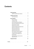
Contents Safety Instructions 5 SAFETY: Rack Mounting of Systems 5 Installation Instructions 6 Rack Requirements 6 Rack Installation 6 Before You Begin 7 Installation Tasks 8 Recommended Tools and Supplies 8 Removing and Replacing the Rack Doors 8 Removing the Front Door 8 Replacing the - Dell PowerEdge Rack Enclosure 4820 | User Manual - Page 6
4 Contents - Dell PowerEdge Rack Enclosure 4820 | User Manual - Page 7
and warranties in connection with such combinations. • System rack kits are intended to be installed in a rack by trained service technicians. If you install the kit in any other rack, be sure that the rack meets the specifications of a Dell rack. Dell™ PowerEdge™ 4210 Installation Guide 5 - Dell PowerEdge Rack Enclosure 4820 | User Manual - Page 8
Electronics Association (CEA) Standard CEA-310-E, International Electrotechnical Commission (IEC) 297, and Deutsche Industrie Norm (DIN) 41494. Rack Installation Before attempting this installation, you should read through this entire procedure carefully. 6 Dell™ PowerEdge™ 4210 Installation Guide - Dell PowerEdge Rack Enclosure 4820 | User Manual - Page 9
The weight of more than one extended system could cause the rack to tip over and cause injury. The stabilizer feet help prevent the rack from tipping over when a system or other component is pulled out of the rack with the slide assemblies fully extended. Dell™ PowerEdge™ 4210 Installation Guide 7 - Dell PowerEdge Rack Enclosure 4820 | User Manual - Page 10
rear door panels Recommended Tools and Supplies You may need the following tools and supplies to install the rack: • #2 Phillips screwdriver • Flat head screwdriver • 12-mm wrench • Needle-nose pliers • open the front door all the way (see Figure 1-1). 8 Dell™ PowerEdge™ 4210 Installation Guide - Dell PowerEdge Rack Enclosure 4820 | User Manual - Page 11
body 2 hinge pin 4 hinge-pin housing 3 While holding the hinge pin out of the door's hinge-pin housing, pull the door slightly away from the rack so that the door clears the hinge body. 4 Release the hinge pin. Dell™ PowerEdge™ 4210 Installation Guide 9 - Dell PowerEdge Rack Enclosure 4820 | User Manual - Page 12
in reverse. Opening and Removing the Back Doors CAUTION: Because of the size and weight of the rack cabinet doors, never attempt to remove or install them by yourself. 1 Open the back doors. release the left door (see Figure 1-2). d Open the left door. 10 Dell™ PowerEdge™ 4210 Installation Guide - Dell PowerEdge Rack Enclosure 4820 | User Manual - Page 13
Back Door 1 2 1 pinch latch 2 door-latch button 2 Remove the right door. a While supporting the door, pull the pin for the top hinge out of the door's hinge-pin housing (see b Repeat step a for the bottom hinge. c Pull the door away from the rack. Dell™ PowerEdge™ 4210 Installation Guide 11 - Dell PowerEdge Rack Enclosure 4820 | User Manual - Page 14
. Laying the door flat with the outer surface facing upward helps prevent damage to its cosmetic coating. e Repeat steps a through d for the left door. 12 Dell™ PowerEdge™ 4210 Installation Guide - Dell PowerEdge Rack Enclosure 4820 | User Manual - Page 15
of the rack cabinet support rails and to reverse the direction that the front door opens. 1 Unlock the locks near the left and right edges of the panel (see Figure 1-4). Figure 1-4. Removing a Side Panel 1 2 3 1 side panel (2) 3 handles (2) 2 locks (2) Dell™ PowerEdge™ 4210 Installation Guide - Dell PowerEdge Rack Enclosure 4820 | User Manual - Page 16
instructions, see "Removing the Side Panels." 3 Reverse the top hinge body. a Pull the hinge pin upward slightly so that you can access the retention clip (see Figure 1-5). b Using the needle-nose pliers, remove the retention clip, and slide the hinge pin out of the hinge body. 14 Dell™ PowerEdge - Dell PowerEdge Rack Enclosure 4820 | User Manual - Page 17
hinge pin, retention clip, and spring in a safe location. e Using the 4-mm Allen wrench, remove the Allen bolt that secures the hinge body to the rack, and place the bolt with the hinge pin, retention clip, and spring. Dell™ PowerEdge™ 4210 Installation Guide 15 - Dell PowerEdge Rack Enclosure 4820 | User Manual - Page 18
now on the right side of the hinge body (see Figure 1-6). Figure 1-6. Reversing the Top and Bottom Hinges 1 2 3 4 5 7 1 hinge pin 3 spring 5 hinge post 7 front of rack 6 2 top hinge body 4 retention clip 6 bottom hinge body 16 Dell™ PowerEdge™ 4210 Installation Guide - Dell PowerEdge Rack Enclosure 4820 | User Manual - Page 19
1-6). c Locate the bottom bolt hole in the right side of the rack, and use the Allen bolt to fasten the hinge body to the right side of the rack. 5 Rotate the front door 180 degrees so that its hinge-pin housings are on the right side (see Figure 1-7). Dell™ PowerEdge™ 4210 Installation Guide 17 - Dell PowerEdge Rack Enclosure 4820 | User Manual - Page 20
horizontal frame member by aligning the holes of the catch with the holes of the frame member and then reinserting the two #2 Phillips screws. 18 Dell™ PowerEdge™ 4210 Installation Guide - Dell PowerEdge Rack Enclosure 4820 | User Manual - Page 21
: Always level the rack and install the stabilizing feet before you install your systems. A fully loaded rack may tip over if your rack is resting on an uneven floor surface and the leveling and stabilizing feet are not supporting the weight of the rack. Dell™ PowerEdge™ 4210 Installation Guide 19 - Dell PowerEdge Rack Enclosure 4820 | User Manual - Page 22
, tighten the hex nut clockwise with a 12-mm wrench (see Figure 1-8). 3 Repeat steps 1 and 2 for the remaining leveling feet. 4 Ensure that the rack is level. Figure 1-8. Adjusting the Leveling Feet 1 2 3 1 leveling foot stem 3 leveling pad 2 hex nut 20 Dell™ PowerEdge™ 4210 Installation Guide - Dell PowerEdge Rack Enclosure 4820 | User Manual - Page 23
the front stabilizer foot against the base of the rack frame and align its holes with the corresponding holes in the frame. 4 Use a 5-mm Allen wrench and the provided Allen bolts to secure the front stabilizer foot to the rack as shown in Figure 1-9. Dell™ PowerEdge™ 4210 Installation Guide 21 - Dell PowerEdge Rack Enclosure 4820 | User Manual - Page 24
: 1 Remove the side panel. 2 On the side of the rack frame's bottom rail, locate the three threaded holes (see Figure 1-10). 3 Position the stabilizer foot against the base of the rack frame and align its holes with the corresponding holes in the frame. 22 Dell™ PowerEdge™ 4210 Installation Guide - Dell PowerEdge Rack Enclosure 4820 | User Manual - Page 25
to the rack frame. NOTE: Unless you need to couple two or more racks, you may now install systems into the rack. Refer to the white numbered labels on the front and back of the rack mounting rails for information on installing components in the rack. Dell™ PowerEdge™ 4210 Installation Guide 23 - Dell PowerEdge Rack Enclosure 4820 | User Manual - Page 26
systems mounted in the rack. • Cable clips mounted on the frame uprights keep cables out of the way and help prevent cords from becoming tangled. Figure 1-11. Cable-Routing Options 2 1 1 cable-routing channels (4) 3 cable exit route 2 cable raceway 24 Dell™ PowerEdge™ 4210 Installation Guide - Dell PowerEdge Rack Enclosure 4820 | User Manual - Page 27
: To protect cables from abrasion, ensure that the plastic grommets are installed in the rack ceiling holes before routing cables to a cable raceway. Some systems may require additional space Optional Door Kit With Removable Panels 1 1 captive screws Dell™ PowerEdge™ 4210 Installation Guide 25 - Dell PowerEdge Rack Enclosure 4820 | User Manual - Page 28
1 Unpack and set up both racks. 2 Unpack the coupling kit, shown in Figure 1-13. The contents of the rack coupling kit include: • Four gasket strips • Four hexagonal spacers • Eight Allen screws • A stamped-metal crescent wrench • A T-handle Allen wrench 26 Dell™ PowerEdge™ 4210 Installation Guide - Dell PowerEdge Rack Enclosure 4820 | User Manual - Page 29
will be inserted into the racks (see Figure 1-14). NOTE: Do not cover the square holes in the rack frame with the gasket strips. It does not matter on which rack you place the gasket strips, as long as the strips protect both racks from being scratched. Dell™ PowerEdge™ 4210 Installation Guide 27 - Dell PowerEdge Rack Enclosure 4820 | User Manual - Page 30
Figure 1-14. Installing the Hexagonal Spacers 1 Allen screws (8) 3 gasket strips (4) 1 2 3 2 hexagonal spacers (4) 28 Dell™ PowerEdge™ 4210 Installation Guide - Dell PowerEdge Rack Enclosure 4820 | User Manual - Page 31
Leveling Feet." c Install the four hexagonal spacers on the front and back of the racks with the provided Allen screws, as shown in Figure 1-14. d Use the stamped metal crescent wrench to hold each hexagonal spacer in turn and tighten the Allen screws. Dell™ PowerEdge™ 4210 Installation Guide 29 - Dell PowerEdge Rack Enclosure 4820 | User Manual - Page 32
30 Dell™ PowerEdge™ 4210 Installation Guide - Dell PowerEdge Rack Enclosure 4820 | User Manual - Page 33
opening, 10 removing, 11 C cables routing, 24 coupling two racks, 26 D doors removing, 8 F front door removing, 8, 10 L leveling feet, 19 R rack mount precautions, 7 rack stabilizer feet, 7, 21 routing cables, 24 S safety instructions, 5 side panels removing, 13-14 stabilizer feet installing front - Dell PowerEdge Rack Enclosure 4820 | User Manual - Page 34
32 Index - Dell PowerEdge Rack Enclosure 4820 | User Manual - Page 35
Dell™ PowerEdge™ 4210 Guide d'installation - Dell PowerEdge Rack Enclosure 4820 | User Manual - Page 36
de ce document, de quelque manière que ce soit, sans l'autorisation écrite de Dell Inc. est strictement interdite. Marques utilisées dans ce document : Dell, le logo DELL et PowerEdge sont des marques de Dell Inc. D'autres marques et noms commerciaux peuvent être utilisés dans ce document pour faire - Dell PowerEdge Rack Enclosure 4820 | User Manual - Page 37
46 Remise en place des panneaux latéraux. . . . . . 47 Inversion de la porte avant (optionnel 47 Fixation des cales du rack 52 Installation des pieds stabilisateurs du rack . . . . 54 Acheminement des câbles 57 Retrait des panneaux de la porte du kit de porte optionnel 59 Association de deux - Dell PowerEdge Rack Enclosure 4820 | User Manual - Page 38
36 Table des matières - Dell PowerEdge Rack Enclosure 4820 | User Manual - Page 39
vous incombe de veiller à ce que la combinaison finale système/rack soit conforme à toutes les normes de sécurité en vigueur ainsi qu'aux normes électriques locales. Dell décline toute responsabilité et toutes garanties liées à ce type de combinaisons. Guide d'installation Dell™ PowerEdge™ 4210 37 - Dell PowerEdge Rack Enclosure 4820 | User Manual - Page 40
service expérimentés pour l'installation d'un rack de 42 unités (U). Elles comprennent notamment des informations sur l'assemblage du rack, l'association de deux racks de 42 U et l'acheminement des câbles à l'intérieur du rack. Le rack Norm (DIN) 41494. 38 Guide d'installation Dell™ PowerEdge™ 4210 - Dell PowerEdge Rack Enclosure 4820 | User Manual - Page 41
un rack qui n'est pas équipé de stabilisateurs avant et latéraux peut provoquer le basculement du rack, et comporte dans certaines situations un risque de blessures. Installez toujours les pieds stabilisateurs avant d'installer les composants dans le rack. Guide d'installation Dell™ PowerEdge™ 4210 - Dell PowerEdge Rack Enclosure 4820 | User Manual - Page 42
en place des pieds stabilisateurs 6 Acheminement des câbles à l'intérieur du rack 7 Association de deux racks (optionnel) 8 Retrait des panneaux de porte arrière compacts Outils et fournitures dans le kit) • Clés des portes et panneaux latéraux du rack 40 Guide d'installation Dell™ PowerEdge™ 4210 - Dell PowerEdge Rack Enclosure 4820 | User Manual - Page 43
Retrait et remise en place des portes du rack PRÉCAUTION : Les portes de l'armoire à rack sont lourdes et volumineuses ; ne tentez jamais de les retirer ou de les installer sans Le clip de retenue de la broche empêche la charnière de sortir du gond. Guide d'installation Dell™ PowerEdge™ 4210 41 - Dell PowerEdge Rack Enclosure 4820 | User Manual - Page 44
rack pour la faire sortir de ses gonds. 4 Relâchez la broche de la charnière. 5 Soulevez la porte afin de libérer la barre de charnière inférieure. PRÉCAUTION : La porte étant lourde et volumineuse, nous vous recommandons de la poser à plat une fois retirée. 42 Guide d'installation Dell™ PowerEdge - Dell PowerEdge Rack Enclosure 4820 | User Manual - Page 45
l'ordre inverse. Ouverture et retrait des portes arrière PRÉCAUTION : Les portes de l'armoire à rack sont lourdes et volumineuses ; ne tentez jamais de les retirer ou de les installer sans assistance. 1 à la Figure 1-2). d Ouvrez la porte de gauche. Guide d'installation Dell™ PowerEdge™ 4210 43 - Dell PowerEdge Rack Enclosure 4820 | User Manual - Page 46
ère sont conçues pour ne pas pouvoir se détacher des gonds. b Répétez l'étape a pour la charnière inférieure. c Tirez la porte hors du rack. 44 Guide d'installation Dell™ PowerEdge™ 4210 - Dell PowerEdge Rack Enclosure 4820 | User Manual - Page 47
de gauche. Remise en place des portes arrière Pour remettre les portes arrière en place, suivez les étapes de retrait dans l'ordre inverse. Guide d'installation Dell™ PowerEdge™ 4210 45 - Dell PowerEdge Rack Enclosure 4820 | User Manual - Page 48
pour l'installation des systèmes dans le rack, l'ouverture des côtés facilite l'installation des assemblages de glissières et des rails de support, ainsi que l'inversion du sens d' latéral 1 2 3 1 panneau latéral (2) 3 poignées (2) 2 verrous (2) 46 Guide d'installation Dell™ PowerEdge™ 4210 - Dell PowerEdge Rack Enclosure 4820 | User Manual - Page 49
charnière supérieure au rack. Pour inverser le sens de l'ouverture de la porte, procédez selon les étapes suivantes : 1 Retirez la porte avant. Pour obtenir des instructions, reportez-vous à la section glisser la broche de la charnière hors du gond. Guide d'installation Dell™ PowerEdge™ 4210 47 - Dell PowerEdge Rack Enclosure 4820 | User Manual - Page 50
te 6 pans qui fixe le gond au rack, puis mettez-le de côté avec la broche, le clip de retenue et le ressort. f Faites pivoter le gond de 180 degrés de sorte que les trous de la broche se retrouvent du côté droit du gond (reportez-vous à la Figure 1-6). 48 Guide d'installation Dell™ PowerEdge™ 4210 - Dell PowerEdge Rack Enclosure 4820 | User Manual - Page 51
g Localisez le trou du boulon supérieur sur le côté droit du rack et fixez le gond au côté droit du rack à l'aide du boulon à tête 6 pans. h Insérez le ressort entre les trous supérieur et inférieur de la broche de la charnière situés sur le gond. Guide d'installation Dell™ PowerEdge™ 4210 49 - Dell PowerEdge Rack Enclosure 4820 | User Manual - Page 52
droit du rack et fixez le gond au côté droit du rack à l'aide du boulon à tête 6 pans. 5 Faites pivoter la porte avant de 180 degrés de sorte que les logements de la broche de la charnière se retrouvent du côté droit (reportez-vous à la Figure 1-7). 50 Guide d'installation Dell™ PowerEdge™ 4210 - Dell PowerEdge Rack Enclosure 4820 | User Manual - Page 53
élément de cadre horizontal central en alignant les trous du crampon sur ceux de l'élément de cadre et réinsérez les deux vis cruciformes no. 2. Guide d'installation Dell™ PowerEdge™ 4210 51 - Dell PowerEdge Rack Enclosure 4820 | User Manual - Page 54
CAUTION : Avant d'installer les systèmes à l'intérieur du rack, calez-le toujours et installez les pieds stabilisateurs. Un rack plein peut basculer s'il repose sur un sol inégal et que les cales et les pieds stabilisateurs ne supportent pas son poids. 52 Guide d'installation Dell™ PowerEdge™ 4210 - Dell PowerEdge Rack Enclosure 4820 | User Manual - Page 55
puissiez pas installer les pieds stabilisateurs. Or ceux-ci empêchent le rack de basculer. 1 À l'aide d'un tournevis, abaissez la cale que le rack est bien calé. Figure 1-8. Réglage des cales 1 2 3 1 tige de cale 3 pied de cale 2 écrou hexagonal Guide d'installation Dell™ PowerEdge™ 4210 53 - Dell PowerEdge Rack Enclosure 4820 | User Manual - Page 56
stabilisateur avant contre la base du cadre du rack et alignez ses trous sur les trous correspondants du cadre. 4 À l'aide d'une clé 6 pans de 5 mm et des boulons 6 pans fournis, fixez le pied stabilisateur avant au rack comme illustré à la Figure 1-9. 54 Guide d'installation Dell™ PowerEdge™ 4210 - Dell PowerEdge Rack Enclosure 4820 | User Manual - Page 57
latéral. 2 Sur le côté du rail inférieur du cadre du rack, localisez les trois trous taraudés (reportez-vous à la Figure 1-10). 3 Placez le pied stabilisateur contre la base du cadre du rack et alignez ses trous sur les trous correspondants du cadre. Guide d'installation Dell™ PowerEdge™ 4210 55 - Dell PowerEdge Rack Enclosure 4820 | User Manual - Page 58
rack, vous pouvez maintenant installer des systèmes à l'intérieur du rack. Reportez-vous aux étiquettes blanches numérotées situées en haut et en bas des rails de montage du rack pour obtenir des informations sur l'installation d'appareils dans le rack. 56 Guide d'installation Dell™ PowerEdge - Dell PowerEdge Rack Enclosure 4820 | User Manual - Page 59
• Quatre canaux d'acheminement des câbles à l'intérieur de chaque collerette du rack permettent d'acheminer les câbles de l'unité de distribution d'alimentation (PDU) vers 3 1 canaux d'acheminement des câbles (4) 2 chemin de câbles 3 sortie des câbles Guide d'installation Dell™ PowerEdge™ 4210 57 - Dell PowerEdge Rack Enclosure 4820 | User Manual - Page 60
vérifiez que les passe-fils en plastique inclus sont bien installés dans les orifices du haut du rack avant d'acheminer les câbles vers un chemin de câble. Il se peut que certains systèmes aient porte optionnel avec panneaux retirables » à la page 59) 58 Guide d'installation Dell™ PowerEdge™ 4210 - Dell PowerEdge Rack Enclosure 4820 | User Manual - Page 61
de la porte comme suit : 1 Installez les portes selon les instructions fournies dans le kit de porte. 2 Ouvrez les portes du rack et localisez les panneaux en haut de chaque porte. 3 Desserrez . 5 Répétez les étapes 3 et 4 pour l'autre panneau de porte. Guide d'installation Dell™ PowerEdge™ 4210 59 - Dell PowerEdge Rack Enclosure 4820 | User Manual - Page 62
6 pans 2 entretoise hexagonale (4) 4 clé à molette estampée 3 Retirez les portes et les panneaux latéraux des deux racks. Reportez-vous aux sections Retrait de la porte avant , Ouverture et retrait des portes arrière et Retrait des panneaux latéraux. 60 Guide d'installation Dell™ PowerEdge™ 4210 - Dell PowerEdge Rack Enclosure 4820 | User Manual - Page 63
Figure 1-14). REMARQUE : Ne recouvrez pas les trous carrés du cadre du rack avec les bandes de joint. Le choix du rack sur lequel les bandes de joint sont placées importe peu, l'important étant que les bandes protègent les deux racks des égratignures. Guide d'installation Dell™ PowerEdge™ 4210 61 - Dell PowerEdge Rack Enclosure 4820 | User Manual - Page 64
Figure 1-14. Installation des entretoises hexagonales 1 2 3 1 vis à 6 pans (8) 3 bandes de joint (4) 2 entretoises hexagonales (4) 62 Guide d'installation Dell™ PowerEdge™ 4210 - Dell PowerEdge Rack Enclosure 4820 | User Manual - Page 65
les quatre entretoises hexagonales à l'avant et à l'arrière des racks à l'aide des vis à 6 pans fournies, comme illustré à la Figure 1-14. d À l'aide de la clé à molette estampée, maintenez chaque entretoise hexagonale et serrez les vis à 6 pans. Guide d'installation Dell™ PowerEdge™ 4210 63 - Dell PowerEdge Rack Enclosure 4820 | User Manual - Page 66
64 Guide d'installation Dell™ PowerEdge™ 4210 - Dell PowerEdge Rack Enclosure 4820 | User Manual - Page 67
câbles acheminement, 57 porte arrière ouverture, 43 retrait, 44 porte avant retrait, 41, 43 portes retrait, 41 précautions de montage du rack, 39 O outils et fournitures, 40 P panneaux latéraux retrait, 46-47 pieds stabilisateurs installation du pied stabilisateur avant, 54 installation du pied - Dell PowerEdge Rack Enclosure 4820 | User Manual - Page 68
66 Index - Dell PowerEdge Rack Enclosure 4820 | User Manual - Page 69
Dell™ PowerEdge™ 4210 Installationshandbuch - Dell PowerEdge Rack Enclosure 4820 | User Manual - Page 70
ältigung oder Wiedergabe in jeglicher Weise ist ohne schriftliche Genehmigung von Dell Inc. strengstens untersagt. In diesem Text verwendete Marken: Dell, das DELL Logo und PowerEdge sind Marken von Dell Inc. Andere in diesem Dokument möglicherweise verwendete Marken und Handelsbezeichnungen dienen - Dell PowerEdge Rack Enclosure 4820 | User Manual - Page 71
Entfernen der Seitenwände 79 Austauschen der Seitenwände 80 Umdrehen der Vordertür (optional 80 Einstellen der höhenverstellbaren Füße des Racks 85 Befestigen der RackStabilisierungsstandfüße 87 Kabelführung 90 Entfernen der Türverkleidung aus dem zusätzlichen Türen-Bausatz 93 Verbinden von - Dell PowerEdge Rack Enclosure 4820 | User Manual - Page 72
70 Inhalt - Dell PowerEdge Rack Enclosure 4820 | User Manual - Page 73
Kombinationen ab. • System-Rack-Kits müssen von geschulten Servicetechnikern in einem Rack installiert werden. Wenn der Einbausatz in ein anderes Rack eingebaut wird, ist zuvor sicherzustellen, daß das Rack die Anforderungen eines Dell Racks erfüllt. Dell™ PowerEdge™ 4210 Installationshandbuch 71 - Dell PowerEdge Rack Enclosure 4820 | User Manual - Page 74
die Freigabevorrichtung für die Komponentenschienen und beim Einschieben und Herausziehen von Komponenten aus dem Rack vorsichtig vor; Sie können sich an den Laufschienen die Finger einklemmen. • Sie diese gesamte Vorgehensweise sorgfältig durch. 72 Dell™ PowerEdge™ 4210 Installationshandbuch - Dell PowerEdge Rack Enclosure 4820 | User Manual - Page 75
System kann das Rack umkippen und Verletzungen verursachen. Die Stabilisierungsstandfüße dienen dazu, das Umkippen des Racks zu verhindern, wenn ein System oder eine andere Komponente bis zum äußersten Anschlag der Laufschienen aus dem Rack gezogen wird. Dell™ PowerEdge™ 4210 Installationshandbuch - Dell PowerEdge Rack Enclosure 4820 | User Manual - Page 76
Installieren der Stabilisierungsstandfüße 6 Durchführen von Kabeln durch das Rack 7 Verbinden von zwei Racks (optional) 8 Entfernen von dichtbestückten rückwärtigen Abdeckungen öffnen Sie die Vordertür anschließend vollständig (siehe Abbildung 1-1). 74 Dell™ PowerEdge™ 4210 Installationshandbuch - Dell PowerEdge Rack Enclosure 4820 | User Manual - Page 77
4 Scharnierstifthalterung 3 Halten Sie den Scharnierstift in seiner Halterung in der Tür und ziehen Sie die Tür leicht vom Rack fort, so dass die Tür das Scharnier freigibt. 4 Lösen Sie den Sicherungsring und ziehen Sie den Scharnierstift heraus. Dell™ PowerEdge™ 4210 Installationshandbuch 75 - Dell PowerEdge Rack Enclosure 4820 | User Manual - Page 78
1-2). b Öffnen Sie die rechte Tür. c Drücken Sie die Stifte der linken Türverriegelung zusammen, um die linke Tür zu entriegeln (siehe Abbildung 1-2). d Öffnen Sie die linke Tür. 76 Dell™ PowerEdge™ 4210 Installationshandbuch - Dell PowerEdge Rack Enclosure 4820 | User Manual - Page 79
Scharnierstifthalterung der Tür entsteht ein Klicken. Die Scharnierstifte verhindern das Herausheben der Tür aus dem Scharnier. b Wiederholen Sie Schritt a beim unteren Scharnier. c Ziehen Sie die Tür aus dem Rack. Dell™ PowerEdge™ 4210 Installationshandbuch 77 - Dell PowerEdge Rack Enclosure 4820 | User Manual - Page 80
die Schritte a bis d für die linke Tür. Einsetzen der Hintertüren Führen Sie zum Einsetzen der Hintertüren die Schritte zum Entfernen in umgekehrter Reihenfolge aus. 78 Dell™ PowerEdge™ 4210 Installationshandbuch - Dell PowerEdge Rack Enclosure 4820 | User Manual - Page 81
die Seitenwände entfernen. Obwohl es zum Installieren von Systemen im Rack nicht unbedingt erforderlich ist, die Seitenwände abzunehmen, erleichtert dies Griffe (2) 2 Verriegelungen (2) 2 Kippen Sie das obere Ende der Seitenwand ein wenig nach außen. Dell™ PowerEdge™ 4210 Installationshandbuch 79 - Dell PowerEdge Rack Enclosure 4820 | User Manual - Page 82
benötigen vielleicht eine Trittleiter, um die Inbusschraube zu erreichen, mit der das obere Scharnier am Rack befestigt ist. Führen Sie die folgenden Schritte aus, um die Seite, nach der sich die und ziehen Sie den Scharnierstift aus dem Scharnier. 80 Dell™ PowerEdge™ 4210 Installationshandbuch - Dell PowerEdge Rack Enclosure 4820 | User Manual - Page 83
Sicherungsring und die Feder gut auf. e Entfernen Sie mit dem 4-mm-Inbusschlüssel die Inbusschraube, mit der das Scharnier am Rack befestigt ist, und bewahren Sie die Schraube zusammen mit dem Scharnierstift, dem Sicherungsring und der Feder gut auf. Dell™ PowerEdge™ 4210 Installationshandbuch 81 - Dell PowerEdge Rack Enclosure 4820 | User Manual - Page 84
Seite des Scharniers befinden (siehe Abbildung 1-6). Abbildung 1-6. Umsetzen des oberen und unteren Scharniers 1 2 3 4 5 6 7 1 Scharnierstift 3 Feder 5 Scharnierbolzen 7 Vorderseite des Racks 2 oberes Scharnier 4 Sicherungsring 6 unteres Scharnier 82 Dell™ PowerEdge™ 4210 Installationshandbuch - Dell PowerEdge Rack Enclosure 4820 | User Manual - Page 85
der rechten Rackseite und schrauben Sie das Scharnier mit der Inbusschraube an der rechten Seite des Racks fest. 5 Drehen Sie die Vordertür um 180 Grad, sodass sich die Scharnierstifthalterungen auf der rechten Seite befinden (siehe Abbildung 1-7). Dell™ PowerEdge™ 4210 Installationshandbuch 83 - Dell PowerEdge Rack Enclosure 4820 | User Manual - Page 86
Rahmenteil. Bringen Sie dazu die Löcher des Türverschlusses in Übereinstimmung mit den Löchern auf dem Rahmenteil und drehen Sie dann die beiden Inbusschrauben ein. 84 Dell™ PowerEdge™ 4210 Installationshandbuch - Dell PowerEdge Rack Enclosure 4820 | User Manual - Page 87
des Racks gleichmäßig von allen Füßen getragen wird und verhindert, dass das Rack nach einer Richtung hin kippen kann. Wenn die höhenverstellbaren Füße nicht alle fest auf dem Boden aufliegen, könnte das Rack das Gleichgewicht verlieren und umkippen. Dell™ PowerEdge™ 4210 Installationshandbuch - Dell PowerEdge Rack Enclosure 4820 | User Manual - Page 88
üße möglicherweise nicht befestigen. Diese sind aber als Kippschutz für das Rack notwendig. 1 Drehen Sie mit einem Schraubendreher den höhenverstellbaren Fuß die übrigen höhenverstellbaren Füße. 4 Stellen Sie sicher, dass das Rack waagerecht steht. 86 Dell™ PowerEdge™ 4210 Installationshandbuch - Dell PowerEdge Rack Enclosure 4820 | User Manual - Page 89
stehenden Rack. • Befestigen Sie Stabilisierungsstandfüße vorne an allen nebeneinander in einer Reihe aufgestellten Racks und installieren Sie einen linken oder rechten Stabilisierungsstandfuß an den beiden an den Enden der Reihe aufgestellten Racks. Dell™ PowerEdge™ 4210 Installationshandbuch - Dell PowerEdge Rack Enclosure 4820 | User Manual - Page 90
Sie mit einem 5-mm-Inbusschlüssel und den mitgelieferten Inbusschrauben den vordere Stabilisierungsstandfuß am Rack, wie in Abbildung 1-9 gezeigt. Abbildung 1-9. Befestigen des vorderen Stabilisierungsstandfußes 1 1 vorderer Stabilisierungsstandfuß 88 Dell™ PowerEdge™ 4210 Installationshandbuch - Dell PowerEdge Rack Enclosure 4820 | User Manual - Page 91
und bringen Sie seine Löcher mit den entsprechenden Löchern im Rahmen zur Deckung. Abbildung 1-10. Befestigen des seitlichen Stabilisierungsstandfußes 1 1 Befestigungsfläche des Stabilisierungsstandfußes Dell™ PowerEdge™ 4210 Installationshandbuch 89 - Dell PowerEdge Rack Enclosure 4820 | User Manual - Page 92
Rackflansch ermöglichen Ihnen das Verlegen der Kabel der Leistungsverteilungseinheit (PDU) zu den im Rack installierten Systemen. • Kabelklammern an den senkrecht laufenden Rahmenteilen sorgen für sicheren Halt und verhindern das Verwirren von Kabeln. 90 Dell™ PowerEdge™ 4210 Installationshandbuch - Dell PowerEdge Rack Enclosure 4820 | User Manual - Page 93
le (4) 3 Kabeldurchführung 3 2 Kabelkanal Sie können Kabel auf zwei Wegen standardmäßignach außerhalb des Racks legen: • Durch die Aussparung am Fußende der Hintertüren (siehe Abbildung 1-11) • Nach oben führen, um die Kabel vor Abrieb zu schützen. Dell™ PowerEdge™ 4210 Installationshandbuch 91 - Dell PowerEdge Rack Enclosure 4820 | User Manual - Page 94
Kabelführung zu haben: ANMERKUNG: Einen zusätzlichen Türen-Bausatz können Sie bei Dell bestellen. Sehen Sie dazu in den Bestellanweisungen nach, die Ihrem System beigepackt sind. ren-Bausatz mit abnehmbaren Verkleidungen 1 1 unverlierbare Schrauben 92 Dell™ PowerEdge™ 4210 Installationshandbuch - Dell PowerEdge Rack Enclosure 4820 | User Manual - Page 95
aus wie in Abbildung 1-13. Der Rack-Verbindungs-Bausatz enthält: • Vier Schutzstreifen • Vier sechseckige Abstandstücke • Acht Inbusschrauben • Ein gestanzter verstellbarer Metallschraubenschlüssel • Ein Sechskantschraubenschlüssel mit Knebelgriff Dell™ PowerEdge™ 4210 Installationshandbuch 93 - Dell PowerEdge Rack Enclosure 4820 | User Manual - Page 96
Abstandstücke in die Racks gesteckt werden. (siehe Abbildung 1-14). ANMERKUNG: Verdecken Sie die rechteckigen Löcher im Rackrahmen nicht mit den Schutzstreifen. Es ist egal, auf welches Rack sie die Schutzstreifen platzieren, solange sie beide Racks gegen Kratzer schützen. 94 Dell™ PowerEdge™ 4210 - Dell PowerEdge Rack Enclosure 4820 | User Manual - Page 97
Abbildung 1-14. Anbringen der sechseckigen Abstandstücke 1 2 1 Inbusschrauben (8) 3 Schutzstreifen (4) 3 2 sechseckige Abstandstücke (4) Dell™ PowerEdge™ 4210 Installationshandbuch 95 - Dell PowerEdge Rack Enclosure 4820 | User Manual - Page 98
den mitgelieferten Inbusschrauben an den Vorder- und Rückseiten der Racks, wie in Abbildung 1-14 gezeigt. d Halten Sie mit dem gestanzten verstellbaren Metallschraubenschlüssel die sechseckigen Abstandhalter fest und drehen Sie die Inbusschrauben ein. 96 Dell™ PowerEdge™ 4210 Installationshandbuch - Dell PowerEdge Rack Enclosure 4820 | User Manual - Page 99
der vorderen Stabilisierungsstandfüße, 87 Befestigen des seitlichen Stabilisierungsstandfußes, 89 T Türen entfernen, 74 K Kabel Kabelführung, 90 R Rack-Stabilisierungsstandfüße, 73, 87 S Seitenwände entfernen, 79 Entfernen der, 80 Sicherheitshinweise, 71 V Verlegen von Kabeln, 90 Vordert - Dell PowerEdge Rack Enclosure 4820 | User Manual - Page 100
Stichwortverzeichnis 98 - Dell PowerEdge Rack Enclosure 4820 | User Manual - Page 101
Dell™ PowerEdge™ 4210 - Dell PowerEdge Rack Enclosure 4820 | User Manual - Page 102
2007 Dell Inc Dell Inc Dell、DELL PowerEdge は、Dell Inc Dell Inc 2007 年 10 月 P/N FX668 Rev. A00 - Dell PowerEdge Rack Enclosure 4820 | User Manual - Page 103
目次 103 103 104 104 104 104 105 105 106 106 108 108 110 110 111 111 116 117 119 121 2 122 125 目次 101 - Dell PowerEdge Rack Enclosure 4820 | User Manual - Page 104
102 目次 - Dell PowerEdge Rack Enclosure 4820 | User Manual - Page 105
1 2 警告 : 1 2 1 Dell™ PowerEdge™ 4210 103 - Dell PowerEdge Rack Enclosure 4820 | User Manual - Page 106
設置手順 42 U 2 つの 42 U 42 U 42 U ANSI EIA)規格 ANSI/EIA-310-D-92 CEA)規格 CEA-310-E IEC)297 DIN)41494 1 104 Dell™ PowerEdge™ 4210 - Dell PowerEdge Rack Enclosure 4820 | User Manual - Page 107
2 1 2 3 4 5 6 7 2 8 HD 12 mm 4 mm 5 mm Dell™ PowerEdge™ 4210 105 - Dell PowerEdge Rack Enclosure 4820 | User Manual - Page 108
さい。 1 1-1 2 1-1 106 Dell™ PowerEdge™ 4210 - Dell PowerEdge Rack Enclosure 4820 | User Manual - Page 109
図 1-1 1 2 3 4 1 3 2 4 3 4 5 6 Dell™ PowerEdge™ 4210 107 - Dell PowerEdge Rack Enclosure 4820 | User Manual - Page 110
1 a 1-2 b c 1-2 を参 照)。 d 1-2 1 2 1 2 108 Dell™ PowerEdge™ 4210 - Dell PowerEdge Rack Enclosure 4820 | User Manual - Page 111
2 a 1-3 b c 図 1-3 1 3 2 1 3 2 Dell™ PowerEdge™ 4210 109 - Dell PowerEdge Rack Enclosure 4820 | User Manual - Page 112
d e a から d 1 1-4 図 1-4 1 2 3 110 Dell™ PowerEdge™ 4210 - Dell PowerEdge Rack Enclosure 4820 | User Manual - Page 113
1 2) 3 2) 2 2) 2 3 4 1-4 5 6 7 1 6 メモ : 4 mm 1 2 3 a 1-5 b Dell™ PowerEdge™ 4210 111 - Dell PowerEdge Rack Enclosure 4820 | User Manual - Page 114
図 1-5 4 3 5 2 1 6 1 3 5 2 4 6 c d e 4 mm f 180 1-6 112 Dell™ PowerEdge™ 4210 - Dell PowerEdge Rack Enclosure 4820 | User Manual - Page 115
図 1-6 1 2 3 4 5 6 7 1 3 5 7 2 4 6 g Dell™ PowerEdge™ 4210 113 - Dell PowerEdge Rack Enclosure 4820 | User Manual - Page 116
h i j 4 a b 180 1-6 c 5 180 1-7 114 Dell™ PowerEdge™ 4210 - Dell PowerEdge Rack Enclosure 4820 | User Manual - Page 117
図 1-7 6 7 a 2 つの 2 b 180 c 2 つの 2 8 a b 2 c Dell™ PowerEdge™ 4210 115 - Dell PowerEdge Rack Enclosure 4820 | User Manual - Page 118
d 180 e f 手順 b 4 4 9.5 mm 9.5 mm 1 2 12 mm 1-8 3 1 および 2 4 116 Dell™ PowerEdge™ 4210 - Dell PowerEdge Rack Enclosure 4820 | User Manual - Page 119
図 1-8 1 2 3 1 3 2 1 1 2 Dell™ PowerEdge™ 4210 117 - Dell PowerEdge Rack Enclosure 4820 | User Manual - Page 120
3 4 図 1-9 5 mm 図 1-9 1 1 1 2 3 1-10 3 118 Dell™ PowerEdge™ 4210 - Dell PowerEdge Rack Enclosure 4820 | User Manual - Page 121
図 1-10 1 1 4 5 mm 2 42 U 1-11 4 PDU Dell™ PowerEdge™ 4210 119 - Dell PowerEdge Rack Enclosure 4820 | User Manual - Page 122
図 1-11 2 1 1 4) 3 2 2 1-11 • 4 1-11 120 Dell™ PowerEdge™ 4210 - Dell PowerEdge Rack Enclosure 4820 | User Manual - Page 123
HD 3 DELL 121 図 1-12 1 1 ネジ 1 2 3 一度に 1 4 5 手順 3 および 4 Dell™ PowerEdge™ 4210 121 - Dell PowerEdge Rack Enclosure 4820 | User Manual - Page 124
2 1 2 1-13 • 4 4 8 T 図 1-13 3 1 2 4 5 1 4) 3 8) 5 T 2 4) 4 スパナ 3 4 4 4 1 1-14 122 Dell™ PowerEdge™ 4210 - Dell PowerEdge Rack Enclosure 4820 | User Manual - Page 125
図 1-14 1 8) 3 4) 1 2 3 2 4) Dell™ PowerEdge™ 4210 123 - Dell PowerEdge Rack Enclosure 4820 | User Manual - Page 126
5 a 2 b 2 c 図 1-14 4 d 124 Dell™ PowerEdge™ 4210 - Dell PowerEdge Rack Enclosure 4820 | User Manual - Page 127
索引 番号 2 122 あ 103 け 119 119 そ 110-111 と 106 は 108 109 こ 105 す 116 118 117 ら 105, 117 104 せ 106, 108 索引 125 - Dell PowerEdge Rack Enclosure 4820 | User Manual - Page 128
126 索引 - Dell PowerEdge Rack Enclosure 4820 | User Manual - Page 129
Dell™ PowerEdge™ 4210 Guía de instalación - Dell PowerEdge Rack Enclosure 4820 | User Manual - Page 130
Queda prohibida su reproducción en cualquier medio sin la autorización por escrito de Dell Inc. Marcas comerciales utilizadas en este texto: Dell, el logotipo DELL y PowerEdge son marcas comerciales de Dell Inc. Otras marcas y otros nombres comerciales pueden utilizarse en este documento para hacer - Dell PowerEdge Rack Enclosure 4820 | User Manual - Page 131
Contenido Instrucciones de seguridad 131 SEGURIDAD: Montaje de estantes para los sistemas 131 Instrucciones de instalación 132 Requisitos para el estante 132 Instalación de estantes 133 Antes de comenzar 133 Tareas de instalación 134 Herramientas y materiales recomendados . . . . 134 - Dell PowerEdge Rack Enclosure 4820 | User Manual - Page 132
130 Contenido - Dell PowerEdge Rack Enclosure 4820 | User Manual - Page 133
tiene certificado de seguridad como unidad independiente y como componente para usar en un mueble de estante Dell mediante el kit de estante del cliente. La instalación de su sistema y del kit de ste cumpla con las especificaciones de un estante Dell. Dell™ PowerEdge™ 4210 Guía de instalación 131 - Dell PowerEdge Rack Enclosure 4820 | User Manual - Page 134
electrónica de consumo, CEA) CEA-310-E, International Electrotechnical Commission (Comisión electrotécnica internacional, IEC) 297 y la Norma de la industria alemana (DIN) 41494. 132 Dell™ PowerEdge™ 4210 Guía de instalación - Dell PowerEdge Rack Enclosure 4820 | User Manual - Page 135
que podría causar daños físicos a personas en determinadas circunstancias. Por lo tanto, instale siempre la pata estabilizadora antes de instalar componentes en el estante. Dell™ PowerEdge™ 4210 Guía de instalación 133 - Dell PowerEdge Rack Enclosure 4820 | User Manual - Page 136
puertas de gabinete del estante, nunca intente retirarlas o instalarlas usted mismo. PRECAUCIÓN: guarde las puertas donde no puedan dañar a nadie si caen accidentalmente. 134 Dell™ PowerEdge™ 4210 Guía de instalación - Dell PowerEdge Rack Enclosure 4820 | User Manual - Page 137
bisagra se salga de sus sitio. Ilustración 1-1. Retirar la puerta frontal 1 2 3 4 1 Botón del pestillo 3 Cuerpo de bisagra 2 Pasador de bisagra 4 Cubierta de pasador de bisagra Dell™ PowerEdge™ 4210 Guía de instalación 135 - Dell PowerEdge Rack Enclosure 4820 | User Manual - Page 138
la puerta derecha (ver Ilustración 1-2). b Abra la puerta derecha. c Presione el pestillo de la puerta izquierda para liberarla (ver Ilustración 1-2). d Abra la puerta izquierda. 136 Dell™ PowerEdge™ 4210 Guía de instalación - Dell PowerEdge Rack Enclosure 4820 | User Manual - Page 139
están diseñadas para prevenir que se salgan del pasador de la bisagra. b Repita el paso A para la bisagra trasera. c Saque la puerta del estante. Dell™ PowerEdge™ 4210 Guía de instalación 137 - Dell PowerEdge Rack Enclosure 4820 | User Manual - Page 140
A hasta el D para la puerta izquierda. Sustitución de las puertas posteriores Para sustituir las puertas posteriores, realice de forma inversa los pasos para extraerlas. 138 Dell™ PowerEdge™ 4210 Guía de instalación - Dell PowerEdge Rack Enclosure 4820 | User Manual - Page 141
. 1 Desbloquee los pestillos que se encuentran cerca de los extremos izquierdos y derechos del panel (ver Ilustración 1-4). Ilustración 1-4. Extraer un panel lateral 1 2 3 1 Panel lateral (2) 3 Manijas (2) 2 Pestillos (2) Dell™ PowerEdge™ 4210 Guía de instalación 139 - Dell PowerEdge Rack Enclosure 4820 | User Manual - Page 142
ón 1-5). b Con unos alicates de punta plana, extraiga el gancho de retención y deslice el pasador de la bisagra hacia fuera del cuerpo de la bisagra. 140 Dell™ PowerEdge™ 4210 Guía de instalación - Dell PowerEdge Rack Enclosure 4820 | User Manual - Page 143
que sujeta el cuerpo de la bisagra en el estante y coloque el tornillo con el pasador de la bisagra, el gancho de retención y el muelle. Dell™ PowerEdge™ 4210 Guía de instalación 141 - Dell PowerEdge Rack Enclosure 4820 | User Manual - Page 144
de bisagra 3 Muelle 5 Puesto de la bisagra 7 Parte frontal del estante 6 2 Cuerpo de la bisagra superior 4 Gancho de retención 6 Cuerpo de la bisagra inferior 142 Dell™ PowerEdge™ 4210 Guía de instalación - Dell PowerEdge Rack Enclosure 4820 | User Manual - Page 145
del estante. 5 Gire 180 grados la puerta frontal, de modo que las cubiertas del pasador de la bisagra queden en el lado derecho (ver Ilustración 1-7). Dell™ PowerEdge™ 4210 Guía de instalación 143 - Dell PowerEdge Rack Enclosure 4820 | User Manual - Page 146
nuevo miembro del cuadro horizontal alineando los orificios del retén con los orificios del miembro del cuadro, y luego reinsertando los dos tornillos Phillips del n.º 2. 144 Dell™ PowerEdge™ 4210 Guía de instalación - Dell PowerEdge Rack Enclosure 4820 | User Manual - Page 147
e instale las patas estabilizadoras. Un estante totalmente cargado puede caerse si se apoya en una superficie irregular y las patas niveladoras y estabilizadoras no soportan su peso. Dell™ PowerEdge™ 4210 Guía de instalación 145 - Dell PowerEdge Rack Enclosure 4820 | User Manual - Page 148
patas niveladoras. 4 Asegúrese de que el estante está nivelado. Ilustración 1-8. Ajustar las patas niveladoras 1 2 3 1 Raíz de pata niveladora 3 Relleno de nivelación 2 Tuerca hexagonal 146 Dell™ PowerEdge™ 4210 Guía de instalación - Dell PowerEdge Rack Enclosure 4820 | User Manual - Page 149
del cuadro. 4 Utilice la llave Allen de 5 mm. y los tornillos correspondientes para asegurar la pata estabilizadora frontal al estante, tal y como de indica en Ilustración 1-9. Dell™ PowerEdge™ 4210 Guía de instalación 147 - Dell PowerEdge Rack Enclosure 4820 | User Manual - Page 150
cadena (ver Ilustración 1-10). 3 Coloque la pata estabilizadora frontal contra la base del cuadro del estante y alinee los orificios con los correspondientes del cuadro. 148 Dell™ PowerEdge™ 4210 Guía de instalación - Dell PowerEdge Rack Enclosure 4820 | User Manual - Page 151
estante. Consulte las etiquetas blancas numeradas en la parte frontal y trasera de los rieles de montaje para informarse sobre cómo instalar componentes en el estante. Dell™ PowerEdge™ 4210 Guía de instalación 149 - Dell PowerEdge Rack Enclosure 4820 | User Manual - Page 152
y evita que se enreden. Ilustración 1-11. Opciones de enrutamiento de cables 2 1 3 1 4 canales de enrutamiento de cables 2 Canal conductor de cables 3 Vía de salida de cables 150 Dell™ PowerEdge™ 4210 Guía de instalación - Dell PowerEdge Rack Enclosure 4820 | User Manual - Page 153
por parte de Dell. Consulte la información de pedidos que se incluye en el embalaje de su sistema. • A través del espacio que aparece en la parte superior de las puertas al extraer los paneles (ver "Paneles extraíbles con kit de puerta opcional" en la página 152) Dell™ PowerEdge™ 4210 Guía de - Dell PowerEdge Rack Enclosure 4820 | User Manual - Page 154
uno. 4 Agarre el lateral del panel y tire hacia arriba para desmontarlos de la puerta. 5 Repita los pasos 3 y 4 en el otro panel de la puerta. 152 Dell™ PowerEdge™ 4210 Guía de instalación - Dell PowerEdge Rack Enclosure 4820 | User Manual - Page 155
su protección, en uno de los estantes adyacentes a las cuatro ubicaciones en las que se insertarán los espaciadores hexagonales en los estantes (ver Ilustración 1-14). Dell™ PowerEdge™ 4210 Guía de instalación 153 - Dell PowerEdge Rack Enclosure 4820 | User Manual - Page 156
las correas protejan los dos estantes contra posibles ralladuras. Ilustración 1-14. Instalación de los espaciadores hexagonales 1 2 1 Tornillos tipo Allen (8) 3 Cintas para juntas (4) 3 2 Espaciadores hexagonales (4) 154 Dell™ PowerEdge™ 4210 Guía de instalación - Dell PowerEdge Rack Enclosure 4820 | User Manual - Page 157
le han proporcionado, como se indica en Ilustración 1-14. d Utilice la llave ajustable de metal para sujetar cada espaciador hexagonal y apriete los tornillos tipo Allen. Dell™ PowerEdge™ 4210 Guía de instalación 155 - Dell PowerEdge Rack Enclosure 4820 | User Manual - Page 158
156 Dell™ PowerEdge™ 4210 Guía de instalación - Dell PowerEdge Rack Enclosure 4820 | User Manual - Page 159
Índice A acoplar dos estantes, 153 C cables canalización, 150 cables de canalización, 150 H herramientas y materiales, 134 I instrucciones de seguridad, 131 patas estabilizadoras instalar la pata estabilizadora lateral, 148 patas niveladoras, 145 precauciones de montaje en estante, 133 puerta - Dell PowerEdge Rack Enclosure 4820 | User Manual - Page 160
158 Índice - Dell PowerEdge Rack Enclosure 4820 | User Manual - Page 161
- Dell PowerEdge Rack Enclosure 4820 | User Manual - Page 162
Printed in China. Imprimé en Chine. Gedruckt in China. Impreso en China Printed on Recycled Paper. www.dell.com | support.dell.com
-
 1
1 -
 2
2 -
 3
3 -
 4
4 -
 5
5 -
 6
6 -
 7
7 -
8
-
9
-
10
-
11
-
12
-
13
-
14
-
15
-
16
-
17
-
18
-
19
-
20
-
21
-
22
-
23
-
24
-
25
-
26
-
27
-
28
-
29
-
30
-
31
-
32
-
33
-
34
-
35
-
36
-
37
-
38
-
39
-
40
-
41
-
42
-
43
-
44
-
45
-
46
-
47
-
48
-
49
-
50
-
51
-
52
-
53
-
54
-
55
-
56
-
57
-
58
-
59
-
60
-
61
-
62
-
63
-
64
-
65
-
66
-
67
-
68
-
69
-
70
-
71
-
72
-
73
-
74
-
75
-
76
-
77
-
78
-
79
-
80
-
81
-
82
-
83
-
84
-
85
-
86
-
87
-
88
-
89
-
90
-
91
-
92
-
93
-
94
-
95
-
96
-
97
-
98
-
99
-
100
-
101
-
102
-
103
-
104
-
105
-
106
-
107
-
108
-
109
-
110
-
111
-
112
-
113
-
114
-
115
-
116
-
117
-
118
-
119
-
120
-
121
-
122
-
123
-
124
-
125
-
126
-
127
-
128
-
129
-
130
-
131
-
132
-
133
-
134
-
135
-
136
-
137
-
138
-
139
-
140
-
141
-
142
-
143
-
144
-
145
-
146
-
147
-
148
-
149
-
150
-
151
-
152
-
153
-
154
-
155
-
156
-
157
-
158
-
159
-
160
-
161
-
162
 |
 |

Dell™ PowerEdge™ 4210
Installation Guide
Guide d'installation
Installationshandbuch
インストールガイ ド
Guía de instalación