Dell PowerEdge Rack Enclosure 4820 Cabling PowerEdge T610
Dell PowerEdge Rack Enclosure 4820 Manual
 |
View all Dell PowerEdge Rack Enclosure 4820 manuals
Add to My Manuals
Save this manual to your list of manuals |
Dell PowerEdge Rack Enclosure 4820 manual content summary:
- Dell PowerEdge Rack Enclosure 4820 | Cabling PowerEdge T610 - Page 1
Cable Routing Procedures for Dell™ PowerEdge™ T610 Systems A Dell™ Technical White Paper Dell™ │ Datacenter Infrastructure Engineering By Chris Kitten and Jose L. Flores March 2011 - Dell PowerEdge Rack Enclosure 4820 | Cabling PowerEdge T610 - Page 2
ANY KIND. © 2011 Dell Inc. All rights reserved. Reproduction of this material in any manner whatsoever without the express written permission of Dell Inc. is strictly forbidden. For more information, contact Dell. Dell, the DELL logo, the DELL badge, and PowerEdge are trademarks of Dell Inc. Page ii - Dell PowerEdge Rack Enclosure 4820 | Cabling PowerEdge T610 - Page 3
Cables Through the Strain Reliefs 3 1.3 Installation of the CMA ...3 Section 2: Cabling a Dell™ PowerEdge™ T610 System Without a CMA 5 2.1 Routing the Cables ...5 Section 3: Replacing a Power Supply on a PowerEdge™ T610 System With a CMA 6 Table of Figures Figure 1: System with Cables Installed - Dell PowerEdge Rack Enclosure 4820 | Cabling PowerEdge T610 - Page 4
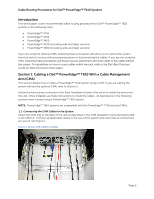
Practices Guide for Rack Enclosures white paper. Section 1: Cabling a Dell™ PowerEdge™ T610 With a Cable Management Arm (CMA) This section details how to cable a PowerEdge™ T610 system using a CMA. If you are cabling the system without the optional CMA, refer to Section 2. Follow the instructions - Dell PowerEdge Rack Enclosure 4820 | Cabling PowerEdge T610 - Page 5
must be partially disconnected in order to remove the lower power supply. Refer to Section 3 for details on power supply replacement. NOTE: For guidelines on how to route cables within the rack, refer to the Dell Best Practices Guide for Rack Enclosures white paper. NOTE: If you are installing fiber - Dell PowerEdge Rack Enclosure 4820 | Cabling PowerEdge T610 - Page 6
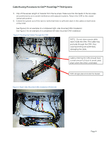
for Dell™ PowerEdge™ T610 Systems 5. Clip off the excess length of material from the tie wraps. Make sure that the heads of the tie wraps are positioned so as to avoid interference with adjacent systems. Return the CMA to the closed (retracted) position. 6. Extend the system out of the rack to - Dell PowerEdge Rack Enclosure 4820 | Cabling PowerEdge T610 - Page 7
Dell™ PowerEdge™ T610 systems is optional. Without the CMA installed, the system must be powered down and all cables disconnected before it can be removed from the rack the Rack Installation Instructions. See Figure 6 for an example of data cables secured to the left CMA bracket and power cables - Dell PowerEdge Rack Enclosure 4820 | Cabling PowerEdge T610 - Page 8
closed (retracted) position. 1. Swing the CMA to its service position. 2. Disengage the strain relief and disconnect the power cord from the power supply. 3. Disconnect the inner CMA attachment housing from the rail as shown in Figure 8. 4. While supporting the CMA with one hand, remove and replace
-
 1
1 -
 2
2 -
 3
3 -
 4
4 -
 5
5 -
 6
6 -
 7
7 -
8
 |
 |

Cable Routing Procedures for
Dell™ PowerEdge™ T610 Systems
A Dell
™
Technical White Paper
Dell
™
│
Datacenter Infrastructure Engineering
By Chris Kitten and Jose L. Flores
March 2011