Dell PowerEdge XR4510c PowerEdge XR4510c Installation and Service Manual
Dell PowerEdge XR4510c Manual
 |
View all Dell PowerEdge XR4510c manuals
Add to My Manuals
Save this manual to your list of manuals |
Dell PowerEdge XR4510c manual content summary:
- Dell PowerEdge XR4510c | PowerEdge XR4510c Installation and Service Manual - Page 1
Dell PowerEdge XR4510c Installation and Service Manual December 2022 Rev. A00 - Dell PowerEdge XR4510c | PowerEdge XR4510c Installation and Service Manual - Page 2
use of your product. CAUTION: A CAUTION indicates either potential damage to hardware or loss of data and tells you how to avoid the problem. WARNING: A WARNING indicates a potential for property damage, personal injury, or death. © 2022 Dell Inc. or its subsidiaries. All rights reserved. Dell - Dell PowerEdge XR4510c | PowerEdge XR4510c Installation and Service Manual - Page 3
Code and Service Tag 11 System information label...12 Chapter 3: Technical specifications 14 Sled dimensions ...14 System weight...15 Processor specifications...15 Cooling fan specifications...15 Supported operating systems...15 System battery specifications...15 Memory specifications...16 Storage - Dell PowerEdge XR4510c | PowerEdge XR4510c Installation and Service Manual - Page 4
45 Boot Manager...45 PXE boot...45 Chapter 7: Minimum configuration to POST 46 Chapter 8: Installing and removing system components 47 Safety instructions...47 Before working inside your system ...47 After working inside your system...48 Recommended tools...48 XR4510c sled...48 Sled installation - Dell PowerEdge XR4510c | PowerEdge XR4510c Installation and Service Manual - Page 5
Diagnostics from the Dell Lifecycle Controller 81 System diagnostic controls...82 Chapter 12: Getting help...83 Recycling or End-of-Life service information...83 Contacting Dell Technologies...83 Accessing system information by using QRL...83 Quick Resource Locator for PowerEdge XR4510c system 84 - Dell PowerEdge XR4510c | PowerEdge XR4510c Installation and Service Manual - Page 6
1 About this document This document provides an overview about the system, information about installing and replacing components, diagnostic tools, and guidelines to be followed while installing certain components. 6 About this document - Dell PowerEdge XR4510c | PowerEdge XR4510c Installation and Service Manual - Page 7
The PowerEdge XR4510c system is a 1U half-width, 1-processor server sled that supports: ● One 3rd Generation Intel Xeon D Scalable processor with up to 20 cores XR4510c • NIC indicator codes • Locating the Express Service Code and Service Tag • System information label System configurations - front - Dell PowerEdge XR4510c | PowerEdge XR4510c Installation and Service Manual - Page 8
Description information, see the Integrated Dell Remote Access Controller User's Guide at www.dell.com/ poweredgemanuals. Enables you to connect a Indicates if the system is powered on or off. Press the power button to manually power on or off the system. NOTE: When XR4510c is installed in the - Dell PowerEdge XR4510c | PowerEdge XR4510c Installation and Service Manual - Page 9
. For more information, see the Integrated Dell Remote Access Controller User's Guide at www.dell.com/ poweredgemanuals. The Information tag is a slideout label Description Connector cover for the sled Power Interposer Board (PIB). Supports 3 Standard (STD) cooling fans. Enables you to connect to - Dell PowerEdge XR4510c | PowerEdge XR4510c Installation and Service Manual - Page 10
System configurations - inside view for PowerEdge XR4510c Figure 3. Inside view of the PowerEdge XR4510c sled 1. Connector cover 3. System board 5. Network I/O ports 7. Information Tag 9. M.2 BOSS N1 Card 11. Fan 2. Fan bracket 4. Processor 6. Sled handle 8. M.2 Riser Module 10. Fan guard 10 - Dell PowerEdge XR4510c | PowerEdge XR4510c Installation and Service Manual - Page 11
, and activity is off. Indicates that the NIC identity is enabled through the NIC configuration utility. Locating the Express Service Code and Service Tag The unique Express Service Code and Service Tag are used to identify the system. The information tag is located on the rear of the system that - Dell PowerEdge XR4510c | PowerEdge XR4510c Installation and Service Manual - Page 12
Tag of your system 1. Information tag (bottom view) 2. iDRAC MAC address information label 3. Information tag (top view) 4. Express Service Tag label Alternatively, the Service Tag information is located on a label on the left wall of the chassis. System information label The system information - Dell PowerEdge XR4510c | PowerEdge XR4510c Installation and Service Manual - Page 13
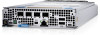
Figure 7. Mechanical overview and ports information Dell PowerEdge XR4510c system configurations and features 13 - Dell PowerEdge XR4510c | PowerEdge XR4510c Installation and Service Manual - Page 14
are outlined in this section. Topics: • Sled dimensions • System weight • Processor specifications • Cooling fan specifications • Supported operating systems • System battery specifications • Memory specifications • Storage controller specifications • Drives • Ports and connectors specifications - Dell PowerEdge XR4510c | PowerEdge XR4510c Installation and Service Manual - Page 15
fan specifications Fan type Standard (STD) fans (60 mm cable length) Label color No label Label image Supported operating systems The PowerEdge XR4510c system supports the following operating systems: ● Azure Stack HCI ● Canonical Ubuntu Server LTS ● Microsoft Windows Server with Hyper-V ● Red - Dell PowerEdge XR4510c | PowerEdge XR4510c Installation and Service Manual - Page 16
-N1): 2 x M.2 SSDs as internal boot. Drives The PowerEdge XR4510c system supports up to 4 x M.2 SSDs (M.2 2280 and M.2 22110) installed on USB 3.0-compliant One port NIC port specifications The PowerEdge XR4510c system supports up to four Network Interface Controller (NIC) ports embedded on the - Dell PowerEdge XR4510c | PowerEdge XR4510c Installation and Service Manual - Page 17
LAN on Motherboard Specifications 10 GbE x 4 (max 50 Gb), 25 GbE x 4 (max 100 Gb) Serial connector specifications The PowerEdge XR4510c system supports one Micro-USB debug port for Universal Asynchronous Receiver or Transmitter (UART), in front of the system. Display port The PowerEdge XR4510c - Dell PowerEdge XR4510c | PowerEdge XR4510c Installation and Service Manual - Page 18
Table 13. Operating and non-operating temperature considerations Configuration Temperature range Operating temperature range -5 to 55°C with a startup temperature of 0°C Non-operating temperature range -40 to 85°C Environmental Considerations The PowerEdge XR4510c system is targeted for edge - Dell PowerEdge XR4510c | PowerEdge XR4510c Installation and Service Manual - Page 19
1 (Max ASHRAE A4 (Max 50°C) 45°C) Yes Yes Yes Yes Yes Yes Yes Yes Yes Yes Yes Yes Yes Yes Yes Table 17. M.2 Support Thermal Limitation for XR4000r Chassis (RAF Configurations) M.2 Type Edge 2 (Max 55°C) Riser Module Edge 1 (Max 50°C) ASHRAE A4 (Max 45°C) BOSS Module Edge - Dell PowerEdge XR4510c | PowerEdge XR4510c Installation and Service Manual - Page 20
Not Not Yes Not Not Yes Not Not Yes 480GB Supporte Supported Supported Supported Supported Supporte d d Micron Not Not Yes Not Not Yes Not Not Yes 800GB Supporte Supported Supported Supported Supported Supporte d d Micron Not Not Yes Not Not Yes Not Not Yes - Dell PowerEdge XR4510c | PowerEdge XR4510c Installation and Service Manual - Page 21
Hynix Not Not Yes Not Not Yes Not Not Yes 480GB Supporte Supported Supported Supported Supported Supporte d d Hynix Not Not Yes Not Not Yes Not Not Yes 800GB Supporte Supported Supported Supported Supported Supporte d d Hynix Not Not Yes Not Not Yes Not Not Yes - Dell PowerEdge XR4510c | PowerEdge XR4510c Installation and Service Manual - Page 22
(Normal Air Flow Direction) Configurations: ● CPU TDP greater than 120W are not supported within A4. ● Nvidia A30 card is not supported above 45°C environment temperature. ● Nvidia A2 GPU card is not supported above 45°C environment temperature. ● In redundant mode, two power supplies are required - Dell PowerEdge XR4510c | PowerEdge XR4510c Installation and Service Manual - Page 23
for initial setup and configuration of the Dell system. The section also provides general steps to set up the system and the reference guides for detailed information. Topics: • Setting up the system • iDRAC configuration • Options to download drivers and firmware Setting up the system Perform the - Dell PowerEdge XR4510c | PowerEdge XR4510c Installation and Service Manual - Page 24
at https://www.dell.com/idracmanuals or for system specific Integrated Dell Remote Access Controller User's Guide, go to https://www.dell.com/poweredgemanuals > Product Support page of your system > Documentation. NOTE: To determine the most recent iDRAC release for your platform and for latest - Dell PowerEdge XR4510c | PowerEdge XR4510c Installation and Service Manual - Page 25
API Guide available at https://developer.dell.com. Options to download drivers and firmware You can download firmware from the Dell support site. For information about downloading firmware, see the Downloading drivers and firmware section. You can also choose any one of the following options - Dell PowerEdge XR4510c | PowerEdge XR4510c Installation and Service Manual - Page 26
at https://www.dell.com/idracmanuals or for system specific Integrated Dell Remote Access Controller User's Guide, go to https://www.dell.com/ poweredgemanuals > Product Support page of your system > Documentation. NOTE: To determine the most recent iDRAC release for your platform and for latest - Dell PowerEdge XR4510c | PowerEdge XR4510c Installation and Service Manual - Page 27
firmware. Steps 1. Go to www.dell.com/support/drivers. 2. Enter the Service Tag of the system in the Enter a Dell Service Tag, Dell EMC Product ID or Model field, and then press Enter. NOTE: If you do not have the Service Tag, click Browse all products, and navigate to your product. 3. On - Dell PowerEdge XR4510c | PowerEdge XR4510c Installation and Service Manual - Page 28
enable or disable various iDRAC parameters by using the iDRAC settings utility. For more information about this utility, see Integrated Dell Remote Access Controller User's Guide at www.dell.com/ poweredgemanuals. 28 Pre-operating system management applications - Dell PowerEdge XR4510c | PowerEdge XR4510c Installation and Service Manual - Page 29
Tag Settings Description Enables you to configure device settings for devices such as storage controllers or network cards. Enables you to configure the System Service Tag. System BIOS To view the System BIOS screen, power on the system, press F2, and click System Setup Main Menu > System BIOS - Dell PowerEdge XR4510c | PowerEdge XR4510c Installation and Service Manual - Page 30
is available and is set to Optimizer Mode, by default. Options such as Fault Resilient Mode and NUMA Fault Resilient Mode are available for support when the Advanced RAS capability processor is installed on the system. Specifies the current state of the memory operating mode. Enables or disables the - Dell PowerEdge XR4510c | PowerEdge XR4510c Installation and Service Manual - Page 31
. This option is set to Enabled by default. This option is set to Disabled by default. It is enabled for Secure Launch (Firmware Protection) support on Windows 2022. Optimizes the system for applications that need high utilization of sequential memory access. This option is set to Enabled by default - Dell PowerEdge XR4510c | PowerEdge XR4510c Installation and Service Manual - Page 32
Controls the number of enabled cores in each processor. This option is set to All by default. Limit CPU physical address to 46 bits to support older HyperV. If enabled, automatically disables TME-MT. This option is set to Enabled by default. Specifies the maximum core frequency of the processor. 32 - Dell PowerEdge XR4510c | PowerEdge XR4510c Installation and Service Manual - Page 33
It also enables you to specify the boot order. The Boot Settings only support UEFI mode. ● UEFI: The Unified Extensible Firmware Interface (UEFI) is a consists of data tables with platform related information, boot and runtime service calls that are available to the operating system and its loader. - Dell PowerEdge XR4510c | PowerEdge XR4510c Installation and Service Manual - Page 34
Boot Settings. Table 32. Boot Settings details Option Boot Mode Description Enables you to set the boot mode of the system. If the operating system supports UEFI, you can set this option to UEFI. Setting this field to BIOS allows compatibility with non-UEFI operating systems. This option is set to - Dell PowerEdge XR4510c | PowerEdge XR4510c Installation and Service Manual - Page 35
boot order if you want to boot from a USB key or an optical drive. The following instructions may vary if you have selected BIOS for Boot Mode. NOTE: Changing the drive boot sequence is only supported in BIOS boot mode. Steps 1. On the System Setup Main Menu screen, click System BIOS > Boot - Dell PowerEdge XR4510c | PowerEdge XR4510c Installation and Service Manual - Page 36
is on the PCIe riser 1b. NOTE: Internal USB port is only effective for T150, but T350/R350/R250 are not because hardware does not support. iDRAC Direct USB Port I/OAT DMA Engine Embedded Video Controller The iDRAC Direct USB port is managed by iDRAC exclusively with no host visibility. This - Dell PowerEdge XR4510c | PowerEdge XR4510c Installation and Service Manual - Page 37
. The slot bifurcation field is accessible when set to Manual bifurcation Control and is grayed out when set to Platform Default Bifurcation and Auto Discovery of Bifurcation. NOTE: The slot bifurcation supports on PCIe slot only, does not support slot type from Paddle card to Riser and Slimline - Dell PowerEdge XR4510c | PowerEdge XR4510c Installation and Service Manual - Page 38
Table 38. Serial Communication details (continued) Option Description The options available for System without serial COM port (DB9) are On without Console Redirection, On with Console Redirection, Off. This option is set to Off by default. The options available for System with serial COM port ( - Dell PowerEdge XR4510c | PowerEdge XR4510c Installation and Service Manual - Page 39
Enabled (OS controlled) or when set to Autonomous (if hardware controlled is supported), the processor can operate in all available Power States to save power, is set to Balanced Performance by default. Enables the Monitor/Mwait instructions in the processor. This option is set to Enabled for all - Dell PowerEdge XR4510c | PowerEdge XR4510c Installation and Service Manual - Page 40
performing encryption and decryption by using the Advanced Encryption Standard Instruction Set (AES-NI). This option is set to Enabled Off by default. It is set On for Secure Launch (Firmware Protection) support on Windows 2022. Memory Encryption Enables or disables the Intel Total Memory - Dell PowerEdge XR4510c | PowerEdge XR4510c Installation and Service Manual - Page 41
is set to Random, the system creates a random delay for power up. When this option is set to User Defined, the system delay time is manually to power up. User Defined Delay (120 s to 600 Sets the User Defined Delay option when the User Defined option for AC Power s) Recovery Delay - Dell PowerEdge XR4510c | PowerEdge XR4510c Installation and Service Manual - Page 42
Table 42. System Security details (continued) Option Description Secure Boot Policy Summary Specifies the list of certificates and hashes that secure boot uses to authenticate images. Creating a system and setup password Prerequisites Ensure that the password jumper is enabled. The password - Dell PowerEdge XR4510c | PowerEdge XR4510c Installation and Service Manual - Page 43
Deleting or changing system and setup password Prerequisites NOTE: You cannot delete or change an existing system or setup password if the Password Status is set to Locked. Steps 1. To enter System Setup, press F2 immediately after turning on or restarting your system. 2. On the System Setup Main - Dell PowerEdge XR4510c | PowerEdge XR4510c Installation and Service Manual - Page 44
features on the iDRAC settings needs the iDRAC Enterprise License upgrade. For more information about using iDRAC, see Dell Integrated Dell Remote Access Controller User's Guide at https:// www.dell.com/idracmanuals. 44 Pre-operating system management applications - Dell PowerEdge XR4510c | PowerEdge XR4510c Installation and Service Manual - Page 45
Lifecycle Controller is started during the boot sequence and functions independently of the operating system. NOTE: Certain platform configurations may not support the full set of features provided by the Dell Lifecycle Controller. For more information about setting up the Dell Lifecycle Controller - Dell PowerEdge XR4510c | PowerEdge XR4510c Installation and Service Manual - Page 46
7 Minimum configuration to POST The components listed below are the minimum configuration to POST: ● One memory module (DIMM) ● One power supply unit ● XR4000r or XR4000z chassis (Power Interposer Board, cables) ● System board ● XR4510c sled 46 Minimum configuration to POST - Dell PowerEdge XR4510c | PowerEdge XR4510c Installation and Service Manual - Page 47
only perform troubleshooting and simple repairs as authorized in your product documentation, or as directed by the online or telephone service and support team. Damage due to servicing that is not authorized by Dell is not covered by your warranty. Read and follow the safety instructions that are - Dell PowerEdge XR4510c | PowerEdge XR4510c Installation and Service Manual - Page 48
blank in all the empty slots. Operating the enclosure without a blank results in overheating. Removing a sled blank Prerequisites Follow the safety guidelines listed in Safety instructions. Steps Pull the sled blank to remove it from the enclosure. 48 Installing and removing system components - Dell PowerEdge XR4510c | PowerEdge XR4510c Installation and Service Manual - Page 49
Figure 9. Removing a sled blank from XR4000r Figure 10. Removing the sled blank from XR4000z Next steps Install a sled or a sled blank. Installing a sled blank Prerequisites Follow the safety guidelines listed in Safety instructions. Installing and removing system components 49 - Dell PowerEdge XR4510c | PowerEdge XR4510c Installation and Service Manual - Page 50
11. Installing a sled blank on XR4000r Figure 12. Installing the sled blank on XR4000z Removing the sled Prerequisites Follow the safety guidelines listed in Safety instructions. 50 Installing and removing system components - Dell PowerEdge XR4510c | PowerEdge XR4510c Installation and Service Manual - Page 51
sled out of the enclosure. NOTE: The numbers on the image do not depict the exact steps. The numbers are for representation of sequence. CAUTION: Support the system with both hands while sliding it out of the enclosure. Figure 13. Removing the sled from XR4000r Figure 14. Removing the sled from - Dell PowerEdge XR4510c | PowerEdge XR4510c Installation and Service Manual - Page 52
Next steps Installing the sled Installing the sled Prerequisites Follow the safety guidelines listed in Safety instructions. Steps 1. Pull the blue lever on the sled to free the sled handle. 2. Holding the sled with both hands, align the sled along the sled- - Dell PowerEdge XR4510c | PowerEdge XR4510c Installation and Service Manual - Page 53
Figure 16. Installing the sled into XR4000z Sled cover Removing the sled cover Prerequisites 1. Follow the safety guidelines listed in the Safety instructions. 2. Power off the sled, and any attached peripherals. 3. Follow the steps for Removing a sled. 4. Place the sled on the flat surface with the - Dell PowerEdge XR4510c | PowerEdge XR4510c Installation and Service Manual - Page 54
sled cover Prerequisites 1. Follow the safety guidelines listed in the Safety instructions. 2. Ensure that all internal cables are connected and routed properly the system. Steps 1. Align the tabs on the system cover with the guide slots on the system, as both sides of the top cover have the slots - Dell PowerEdge XR4510c | PowerEdge XR4510c Installation and Service Manual - Page 55
fan Prerequisites 1. Follow the safety guidelines listed in Safety instructions. 2. Follow the procedure listed in Before working inside your fan module. 2. Slightly pull back the fan handle to disengage it from the guiding pin and then lift to release the fan handle. 3. Disconnect the fan cable - Dell PowerEdge XR4510c | PowerEdge XR4510c Installation and Service Manual - Page 56
fan Prerequisites 1. Follow the safety guidelines listed in Safety Instructions. 2. Follow the procedure listed in Before working inside your Natural air-flow (NAF). 6. Pull down the fan handle and push to engage the guiding pin until it clicks into place. NOTE: The numbers on the image do not depict - Dell PowerEdge XR4510c | PowerEdge XR4510c Installation and Service Manual - Page 57
System memory System memory guidelines The PowerEdge XR4510c system supports DDR4 registered DIMMs (RDIMMs) and LRDIMMs. System memory holds the instructions that are executed by the processor. Your system contains 4 memory sockets organized into 4 channels to the processor. Memory channels are - Dell PowerEdge XR4510c | PowerEdge XR4510c Installation and Service Manual - Page 58
performance. ● Odd memory configuration with 3 RDIMMs is not supported. ● Supported RDIMM and LRDIMM configurations are 1, 2, 4 DIMMs. Removing a memory module Prerequisites 1. Follow the safety guidelines listed in Safety instructions. 2. Follow the procedure listed in Before working inside your - Dell PowerEdge XR4510c | PowerEdge XR4510c Installation and Service Manual - Page 59
blank is similar to that of the memory module. . Installing a memory module Prerequisites 1. Follow the safety guidelines listed in Safety instructions. 2. Follow the procedure listed in Before working inside your system. Steps 1. Locate the appropriate memory module socket. CAUTION: Handle each - Dell PowerEdge XR4510c | PowerEdge XR4510c Installation and Service Manual - Page 60
test in system diagnostics. BOSS-N1 card Removing the BOSS-N1 card Prerequisites 1. Follow the safety guidelines listed in the Safety instructions. 2. Follow the procedure listed in Before working inside your system. Steps 1. Using a Phillips 1 screwdriver, loosen the screw that secures the BOSS - Dell PowerEdge XR4510c | PowerEdge XR4510c Installation and Service Manual - Page 61
BOSS-N1 card 2. Replace the M.2 SSD module . Installing the BOSS-N1 card Prerequisites 1. Follow the safety guidelines listed in the Safety instructions. 2. Follow the procedure listed in Before working inside your system. 3. Steps 1. Align and insert the BOSS-N1 card connector with the connector - Dell PowerEdge XR4510c | PowerEdge XR4510c Installation and Service Manual - Page 62
-N1 card Next steps After working inside your system. Removing the M.2 SSD module Prerequisites 1. Follow the safety guidelines listed in Safety instructions. 2. Follow the procedure listed in Before working inside your system. 3. Remove the BOSS-N1 card. Steps 1. Using the Phillips 1 screwdriver - Dell PowerEdge XR4510c | PowerEdge XR4510c Installation and Service Manual - Page 63
After working inside your system. M.2 riser module Removing the M.2 riser module Prerequisites 1. Follow the safety guidelines listed in Safety instructions. 2. Follow the procedure listed in Before working inside your system. Steps 1. Using a Phillips 2 screwdriver, loosen the two captive screws - Dell PowerEdge XR4510c | PowerEdge XR4510c Installation and Service Manual - Page 64
. Removing the M.2 riser Next steps Replace the M.2 Riser. Installing the M.2 riser module Prerequisites 1. Follow the safety guidelines listed in Safety instructions. 2. Follow the procedure listed in Before working inside your system. Steps 1. Align the M.2 module with the system board and insert - Dell PowerEdge XR4510c | PowerEdge XR4510c Installation and Service Manual - Page 65
module Next steps Replace the M.2 SSD module. Installing the M.2 SSD module on the M.2 riser Prerequisites 1. Follow the safety guidelines listed in Safety instructions. 2. Follow the procedure listed in Before working inside your system. 3. Remove the latch on the snap clip and rotate the latch to - Dell PowerEdge XR4510c | PowerEdge XR4510c Installation and Service Manual - Page 66
I/O board Prerequisites 1. Follow the safety guidelines listed in Safety instructions. 2. Follow the procedure listed in Before working inside your the Phillips 2 screwdriver, loosen the blue thumbscrew. CAUTION: Follow the guiding pin to prevent damage to the Network I/O board. 2. Disconnect the - Dell PowerEdge XR4510c | PowerEdge XR4510c Installation and Service Manual - Page 67
Board Install the Network I/O Board Prerequisites 1. Follow the safety guidelines listed in Safety instructions. 2. Follow the procedure listed in Before working inside your system. Steps 1. the 1U sled by aligning it with the help of the guiding pin. Installing and removing system components 67 - Dell PowerEdge XR4510c | PowerEdge XR4510c Installation and Service Manual - Page 68
Board and ensure it is installed correctly. CAUTION: Follow the guiding pin to prevent damage to the Network I/O board. NOTE your system. System battery This is a service technician replaceable part only. Replacing the to the manufacturer's instructions. See the Safety instructions that came with - Dell PowerEdge XR4510c | PowerEdge XR4510c Installation and Service Manual - Page 69
Figure 35. Removing the system battery CAUTION: To avoid damage to the battery connector, you must firmly support the connector while installing or removing a battery. 2. To install a new system battery: a. Push the battery holder clip away. NOTE: Ensure that the + side of the - Dell PowerEdge XR4510c | PowerEdge XR4510c Installation and Service Manual - Page 70
are still incorrect, see Getting help section. System board This is a service technician replaceable part only. Removing the system board Prerequisites CAUTION: If the sled. 1. Follow the safety guidelines listed in Safety instructions. 2. Follow the procedure listed in Before working inside your - Dell PowerEdge XR4510c | PowerEdge XR4510c Installation and Service Manual - Page 71
c. Memory modules d. M.2 BOSS card e. M.2 Riser card f. Network I/O Board g. Disconnect all cables from the system board. CAUTION: Take care not to damage the system identification button while removing the system board from the system. Steps 1. Using a Phillips 2 screwdriver, remove the two screws - Dell PowerEdge XR4510c | PowerEdge XR4510c Installation and Service Manual - Page 72
label in the Information tag with the iDRAC MAC address label of the replacement system board 1. Follow the safety guidelines listed in Safety instructions. 2. Follow the procedure listed in Before working inside your system. 3. If you are replacing the system board, remove all the components that - Dell PowerEdge XR4510c | PowerEdge XR4510c Installation and Service Manual - Page 73
Figure 39. Installing the system board 5. Using a Phillips 2 screwdriver, tighten the screws that secure the connector cover to the system board. Figure 40. Installing the connector cover Next steps 1. Replace the following components: a. Trusted platform module (TPM). NOTE: The TPM Module must be - Dell PowerEdge XR4510c | PowerEdge XR4510c Installation and Service Manual - Page 74
b. If the service tag is not backed up in the backup flash device, enter the system service tag manually. See the Manually update the Service Tag by using information, see the Integrated Dell Remote Access Controller User's Guide available at https://www.dell.com/idracmanuals 5. Follow the - Dell PowerEdge XR4510c | PowerEdge XR4510c Installation and Service Manual - Page 75
Trusted Platform Module This is a service technician replaceable part only. Upgrading the Trusted Platform Module Removing the TPM Prerequisites NOTE: ● Ensure the operating system is compatible with the TPM version you - Dell PowerEdge XR4510c | PowerEdge XR4510c Installation and Service Manual - Page 76
Figure 41. Installing the TPM Initializing TPM for users Steps 1. Initialize the TPM. For more information, see Initializing the TPM for users. 2. The TPM Status changes to Enabled, Activated. Initializing the TPM 2.0 for users Steps 1. While booting your system, press F2 to enter System Setup. 2. - Dell PowerEdge XR4510c | PowerEdge XR4510c Installation and Service Manual - Page 77
9 Upgrade Kits The table lists the available After Point Of Sale [APOS] kits. Table 49. Upgrade kits Kits Related links to service instructions Trusted Platform Module (TPM) See Installing the TPM M.2 SSDs See Installing the M.2 SSD module on M.2 riser Network I/O Board See Installing the - Dell PowerEdge XR4510c | PowerEdge XR4510c Installation and Service Manual - Page 78
10 DIP Switches This topic provides some basic and specific information about DIP switches. DIP switches on the system board help to disable the system and reset the passwords. To set the switches correctly, you must know the location on the system board. Topics: • System board DIP switches • System - Dell PowerEdge XR4510c | PowerEdge XR4510c Installation and Service Manual - Page 79
only perform troubleshooting and simple repairs as authorized in your product documentation, or as directed by the online or telephone service and support team. Damage due to servicing that is not authorized by Dell is not covered by your warranty. Read and follow the safety instructions that are - Dell PowerEdge XR4510c | PowerEdge XR4510c Installation and Service Manual - Page 80
Steps 1. Power off the compute sled and remove the compute sled from chassis. 2. Move the DIP switch on the system board from switches 1 and 2 to switches 2 and 3. NOTE: Use a plastic scribe to change the DIP switch settings. NOTE: The existing passwords are not disabled (erased) until the system - Dell PowerEdge XR4510c | PowerEdge XR4510c Installation and Service Manual - Page 81
is to test the system hardware without using additional equipment or risking data loss. If you are unable to fix the issue yourself, service and support personnel can use the diagnostics results to help you solve the issue. Topics: • Dell Embedded System Diagnostics Dell Embedded System Diagnostics - Dell PowerEdge XR4510c | PowerEdge XR4510c Installation and Service Manual - Page 82
System diagnostic controls Table 51. System diagnostic controls Menu Configuration Results System health Event log Description Displays the configuration and status information of all detected devices. Displays the results of all tests that are run. Provides the current overview of the system - Dell PowerEdge XR4510c | PowerEdge XR4510c Installation and Service Manual - Page 83
components, visit www.dell.com/recyclingworldwide and select the relevant country. Contacting Dell Technologies Dell provides online and telephone based support and service options. If you do not have an active internet connection, you can find Dell contact information on your purchase invoice - Dell PowerEdge XR4510c | PowerEdge XR4510c Installation and Service Manual - Page 84
Installation and Service Manual, and mechanical overview ● The system service tag to Support to troubleshoot the issue. ● Proactive contact - A Dell Technical Support agent contacts you about the support case and helps you resolve the issue. The available benefits vary depending on the Dell Service - Dell PowerEdge XR4510c | PowerEdge XR4510c Installation and Service Manual - Page 85
For information about understanding Remote Access Controller Admin (RACADM) subcommands and supported RACADM interfaces, see the RACADM CLI Guide for iDRAC. For information about Redfish and its protocol, supported schema, and Redfish Eventing implemented in iDRAC, see the Redfish API - Dell PowerEdge XR4510c | PowerEdge XR4510c Installation and Service Manual - Page 86
www.dell.com/poweredgemanuals For information about setting up, using, and troubleshooting OpenManage, see the Dell OpenManage Server Administrator User's Guide. www.dell.com/openmanagemanuals > OpenManage Server Administrator For information about installing and using Dell Secure Connect Gateway
-
 1
1 -
 2
2 -
 3
3 -
 4
4 -
 5
5 -
 6
6 -
 7
7 -
8
-
9
-
10
-
11
-
12
-
13
-
14
-
15
-
16
-
17
-
18
-
19
-
20
-
21
-
22
-
23
-
24
-
25
-
26
-
27
-
28
-
29
-
30
-
31
-
32
-
33
-
34
-
35
-
36
-
37
-
38
-
39
-
40
-
41
-
42
-
43
-
44
-
45
-
46
-
47
-
48
-
49
-
50
-
51
-
52
-
53
-
54
-
55
-
56
-
57
-
58
-
59
-
60
-
61
-
62
-
63
-
64
-
65
-
66
-
67
-
68
-
69
-
70
-
71
-
72
-
73
-
74
-
75
-
76
-
77
-
78
-
79
-
80
-
81
-
82
-
83
-
84
-
85
-
86
 |
 |

Dell PowerEdge XR4510c
Installation and Service Manual
December 2022
Rev. A00