Dell Vostro 14 3446 Dell Vostro 14 3446 Owners Manual
Dell Vostro 14 3446 Manual
 |
View all Dell Vostro 14 3446 manuals
Add to My Manuals
Save this manual to your list of manuals |
Dell Vostro 14 3446 manual content summary:
- Dell Vostro 14 3446 | Dell Vostro 14 3446 Owners Manual - Page 1
Dell Vostro 14 - 3446 Owner's Manual Regulatory Model: P52G Regulatory Type: P52G001 - Dell Vostro 14 3446 | Dell Vostro 14 3446 Owners Manual - Page 2
potential damage to hardware or loss of data and tells you how to avoid the problem. WARNING: A WARNING indicates a potential for property damage, personal injury, or death. Copyright © 2014 Dell Inc. All rights reserved. This product is protected by U.S. and international copyright and intellectual - Dell Vostro 14 3446 | Dell Vostro 14 3446 Owners Manual - Page 3
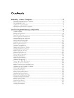
the WLAN Card...15 Installing the WLAN Card...16 Removing the Keyboard...16 Installing the Keyboard...17 Removing the Palmrest...18 Installing the Palmrest...19 Removing the Coin-Cell Battery...20 Installing the Coin-cell battery...20 Removing the Input/Output (I/0) Board 20 Installing the Input - Dell Vostro 14 3446 | Dell Vostro 14 3446 Owners Manual - Page 4
and Setup Password 39 Deleting or Changing an Existing System and/or Setup Password 39 4 Diagnostics...41 Enhanced Pre-Boot System Assessment (ePSA) Diagnostics 41 5 Specifications...43 Specifications...43 6 Contacting Dell...49 Contacting Dell...49 - Dell Vostro 14 3446 | Dell Vostro 14 3446 Owners Manual - Page 5
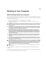
only perform troubleshooting and simple repairs as authorized in your product documentation, or as directed by the online or telephone service and support team. Damage due to servicing that is not authorized by Dell is not covered by your warranty. Read and follow the safety instructions that came - Dell Vostro 14 3446 | Dell Vostro 14 3446 Owners Manual - Page 6
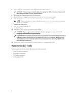
avoid damaging the system board, you must remove the main battery before you service the computer. 7. Remove the main battery. 8. Turn the computer top-side up. 9. Open any installed ExpressCards or Smart Cards from the appropriate slots. Recommended Tools The procedures in this document may require - Dell Vostro 14 3446 | Dell Vostro 14 3446 Owners Manual - Page 7
- Using a touch-enabled device: a. Swipe in from the right edge of the screen, opening the Charms menu and select Settings. b. Select the - Using a mouse: computer, use only the battery designed for this particular Dell computer. Do not use batteries designed for other Dell computers. 1. Connect any - Dell Vostro 14 3446 | Dell Vostro 14 3446 Owners Manual - Page 8
5. Turn on your computer. 8 - Dell Vostro 14 3446 | Dell Vostro 14 3446 Owners Manual - Page 9
2 Removing and Installing Components This section provides detailed information on how to remove or install the components from your computer. System Overview Figure 1. Front View 1. display 3. palmrest assembly 2. keyboard 9 - Dell Vostro 14 3446 | Dell Vostro 14 3446 Owners Manual - Page 10
Figure 2. Back View 1. battery 2. access panel 3. optical-disk drive Figure 3. Inside View - Back 1. memory module 3. hard drive 10 2. WLAN card - Dell Vostro 14 3446 | Dell Vostro 14 3446 Owners Manual - Page 11
Board View 1. I/O board 3. coin-cell battery 5. system fan 2. speakers 4. system board 6. power connector Removing the Battery 1. Follow the procedures in Before Working Inside Your Computer. 2. Slide the release latches outwards to unlock the battery and lift the battery to remove it from the - Dell Vostro 14 3446 | Dell Vostro 14 3446 Owners Manual - Page 12
Installing the Battery 1. Insert the battery into the battery slot and press to lock in place. 2. Follow the procedures in After Working Inside Your Computer. Removing Your Computer. Removing the Access Panel 1. Follow the procedures in Before Working Inside Your Computer. 2. Remove the battery. 12 - Dell Vostro 14 3446 | Dell Vostro 14 3446 Owners Manual - Page 13
chassis. 3. Follow the procedures in After Working Inside Your Computer. Removing the Hard Drive 1. Follow the procedures in Before Working Inside Your Computer. 2. Remove the battery. 3. Remove the access panel. 13 - Dell Vostro 14 3446 | Dell Vostro 14 3446 Owners Manual - Page 14
Drive 1. Slide the hard drive into the connector and then tighten the screw to secure it to the chassis. 2. Install: a. access panel b. battery 3. Follow the procedures in After Working Inside Your Computer. Removing the Memory Module 1. Follow the procedures in Before Working Inside Your Computer - Dell Vostro 14 3446 | Dell Vostro 14 3446 Owners Manual - Page 15
Memory Module 1. Insert the memory module into the socket and press to lock the securing clips. 2. Install the access panel. 3. Install the battery. 4. Follow the procedures in After Working Inside Your Computer. Removing the WLAN Card 1. Follow the procedures in Before Working Inside Your Computer - Dell Vostro 14 3446 | Dell Vostro 14 3446 Owners Manual - Page 16
into its slot and tighten the screw to secure it to the system board. 2. Connect the two connectors (black cable to the black triangle and white cable to the white triangle). 3. Install: a. access panel b. battery 4. Follow the procedures in After Working Inside Your Computer. Removing the Keyboard - Dell Vostro 14 3446 | Dell Vostro 14 3446 Owners Manual - Page 17
up to remove it from the computer. Installing the Keyboard 1. Connect the keyboard cable to the connector on the system board. 2. Slide the keyboard into the retaining slots. 3. Press the top edge to lock the keyboard in place. 4. Install the battery. 5. Follow the procedures in After Working Inside - Dell Vostro 14 3446 | Dell Vostro 14 3446 Owners Manual - Page 18
Removing the Palmrest 1. Follow the procedures in Before Working Inside Your Computer. 2. Remove the battery. 3. Remove the keyboard. 4. Turn the computer over and remove the screws at the base of the computer. Then, release the tabs securing the base cover. 5. Turn the computer - Dell Vostro 14 3446 | Dell Vostro 14 3446 Owners Manual - Page 19
over and press at the edges to lock into the retaining tabs. 5. Tighten the screws at the base of the computer. 6. Install: a. keyboard b. memory module c. hard-disk drive d. WLAN card e. access panel f. optical-disk drive g. battery 7. Follow the procedures in After Working Inside Your Computer. 19 - Dell Vostro 14 3446 | Dell Vostro 14 3446 Owners Manual - Page 20
Push the coin-cell release latch and pull the coin-cell battery to remove it from the computer. Installing the Coin-cell battery 1. Insert the coin-cell battery and press to lock. 2. Install: a. palmrest assembly b. keyboard c. memory module d. hard-disk drive e. WLAN card f. access panel g. optical - Dell Vostro 14 3446 | Dell Vostro 14 3446 Owners Manual - Page 21
the chassis. 2. Connect the I/O board connector to the system board. 3. Install: a. palmrest assembly b. keyboard c. memory module d. hard-disk drive e. WLAN card f. access panel g. optical-disk drive h. battery 4. Follow the procedures in After Working Inside Your Computer. Removing the Speakers - Dell Vostro 14 3446 | Dell Vostro 14 3446 Owners Manual - Page 22
3. Disconnect the speaker connector from the system board (1) and release the speaker cables from the retaining tabs (2). 4. Release the speaker assembly from the retaining clips (1) and remove the speakers from the chassis (2). Installing the Speakers 1. Insert the speakers into the chassis and - Dell Vostro 14 3446 | Dell Vostro 14 3446 Owners Manual - Page 23
the System Board 1. Follow the procedures in Before Working Inside Your Computer. 2. Remove: a. battery b. optical disk drive c. access panel d. hard-disk drive e. memory module f. keyboard g. palmrest assembly 3. Disconnect the following cables from the system board: a. speaker and power connector - Dell Vostro 14 3446 | Dell Vostro 14 3446 Owners Manual - Page 24
4. Remove the screws securing the system board to the chassis. Then, disconnect and remove the following: a. I/O board cable (1) and (2) b. LVDS connector (3) c. LVDS cable(4) 5. Lift and remove the system board from the chassis. Installing the System Board 1. Insert the system board into the - Dell Vostro 14 3446 | Dell Vostro 14 3446 Owners Manual - Page 25
. Removing the Display Assembly 1. Follow the procedures in Before Working Inside Your Computer. 2. Remove: a. battery b. optical disk drive c. access panel d. hard-disk drive e. memory module f. keyboard g. palmrest assembly h. system board 3. Un-thread the WLAN cable and remove the screws securing - Dell Vostro 14 3446 | Dell Vostro 14 3446 Owners Manual - Page 26
4. Place the display panel on a stable surface and gently pry the display bezel away from the panel. 5. Remove the screws securing the display hinges to the display assembly. Then, lift and remove the display hinges away from the display assembly. 26 - Dell Vostro 14 3446 | Dell Vostro 14 3446 Owners Manual - Page 27
display assembly. 3. Tighten the screws to secure the display hinges to the display assembly. 4. Align and press in the display bezel to the display assembly. 5. Guide the WLAN cables through their tabs and then tighten the display hinge screws to secure the display assembly. 27 - Dell Vostro 14 3446 | Dell Vostro 14 3446 Owners Manual - Page 28
Removing the Camera 1. Follow the procedures in Before Working Inside Your Computer. 2. Remove: a. battery b. optical disk drive c. access panel d. hard-disk drive e. memory module f. keyboard g. palmrest assembly h. system board i. display assembly 3. Disconnect the camera connector. Then, release - Dell Vostro 14 3446 | Dell Vostro 14 3446 Owners Manual - Page 29
. 2. Connect the camera connector. 3. Install: a. display bezel b. display assembly c. palmrest assembly d. keyboard e. memory module f. hard-disk drive g. WLAN card h. access panel i. optical-disk drive j. battery 4. Follow the procedures in After Working Inside Your Computer. Removing the Heatsink - Dell Vostro 14 3446 | Dell Vostro 14 3446 Owners Manual - Page 30
the cooling fan's connector to the system board. 3. Install: a. system board b. palmrest assembly c. keyboard d. memory module e. hard-disk drive f. WLAN card g. access panel h. optical-disk drive i. battery 4. Follow the procedures in After Working Inside Your Computer. Removing the Power Connector - Dell Vostro 14 3446 | Dell Vostro 14 3446 Owners Manual - Page 31
connector into its slot on the chassis and guide the cable into the retaining tabs. 2. Connect the power connector cable to the system board. 3. Install: a. palmrest assembly b. keyboard c. memory module d. hard-disk drive e. WLAN card f. access panel g. optical-disk drive h. battery 4. Follow the - Dell Vostro 14 3446 | Dell Vostro 14 3446 Owners Manual - Page 32
32 - Dell Vostro 14 3446 | Dell Vostro 14 3446 Owners Manual - Page 33
and boot directly to a specific device (for example: optical drive or hard drive). During the Power-on Self Test (POST), when the Dell logo appears, you can: display the ePSA diagnostics screen. The boot sequence screen also displays the option to access the System Setup screen. Navigation Keys The - Dell Vostro 14 3446 | Dell Vostro 14 3446 Owners Manual - Page 34
Moves to the previous page till you view the main screen. Pressing in the main screen displays a message that prompts you to save any unsaved Table 2. Main Options Option System Time System Date BIOS Version Product Name Service Tag Asset Tag CPU Type Description Allows you to reset the time - Dell Vostro 14 3446 | Dell Vostro 14 3446 Owners Manual - Page 35
model number and capacity of the hard drive. Displays the model number and capacity of the optical drive. Displays the type of the AC adapter. Displays the system memory installed on the computer. Displays the extended memory on the computer. Displays the memory speed. The Advanced tab allows you - Dell Vostro 14 3446 | Dell Vostro 14 3446 Owners Manual - Page 36
Option Integrated NIC USB Emulation USB Wake Support SATA Operation Adapter Warnings Function Key Behavior Battery Health Miscellaneous Devices External USB Ports Microphone Camera Internal Bluetooth Internal WLAN Media Card Reader Optical Drive Boot Disable USB debug Description Enable or disable - Dell Vostro 14 3446 | Dell Vostro 14 3446 Owners Manual - Page 37
The Security tab displays the security status and allows you to manage the security features of the computer. Table 4. Security Options Option Unlock Setup Status Admin Password System Password HDD Password State Password Change Password Bypass Computrace Secure Boot Mode Description This field - Dell Vostro 14 3446 | Dell Vostro 14 3446 Owners Manual - Page 38
computer. 2. Go to dell.com/support. 3. Enter the Service Tag or Express Service Code and click Submit. NOTE: To locate the Service Tag, click Where is my Service Tag? NOTE: If you cannot find your Service Tag, click Detect My Product. Proceed with the instructions on screen. 4. If you are unable - Dell Vostro 14 3446 | Dell Vostro 14 3446 Owners Manual - Page 39
immediately after a power-on or re-boot. 1. In the System BIOS or System Setup screen, select System Security and press . The System Security screen appears. 2. In the System Security screen, verify that Password Status is Unlocked. 3. Select System Password , enter your system password, and - Dell Vostro 14 3446 | Dell Vostro 14 3446 Owners Manual - Page 40
40 - Dell Vostro 14 3446 | Dell Vostro 14 3446 Owners Manual - Page 41
View error messages that inform you of problems encountered during testing CAUTION: Use the system error messages. NOTE: Some tests for specific devices require user interaction. Always ensure that the key as the Dell logo appears. 3. On the boot menu screen, select the Diagnostics option. The - Dell Vostro 14 3446 | Dell Vostro 14 3446 Owners Manual - Page 42
42 - Dell Vostro 14 3446 | Dell Vostro 14 3446 Owners Manual - Page 43
Specifications Specifications NOTE: Offerings may vary by region. For more information regarding the configuration of your computer, click Start (Start icon) → Help and Support • 4th Generation Intel Core i3 Processor (U-Processor Line) • 4th Generation Intel Core i5 Processor (U-Processor Line) • - Dell Vostro 14 3446 | Dell Vostro 14 3446 Owners Manual - Page 44
Video Feature Video type Video Controller: UMA Discrete Data bus: External display support Table 11. Camera Feature Camera Resolution Video Resolution (maximum) Diagonal viewing angle Table 12. Communication Feature Network adapter Wireless Table 13. Ports and Connectors Feature Audio Video Network - Dell Vostro 14 3446 | Dell Vostro 14 3446 Owners Manual - Page 45
supports Microsoft Kernel Debugging. The ports are identified in the documentation shipped with your computer. Media card reader one 3-in-1 slot Hz 40° / 40° 10° / 30° 0.2265 mm x 0.2265 mm Table 15. Keyboard Feature Number of keys: Description US 102, Brazil 105, UK 103 and Japan 106 Table 16. - Dell Vostro 14 3446 | Dell Vostro 14 3446 Owners Manual - Page 46
Feature Type Dimensions: Height Width Depth Weight Life span Voltage Temperature range: Operating Non-Operating Coin-cell battery Table 18. AC Adapter Feature Type Input voltage Input current (maximum) Input frequency Output power Output current Rated output voltage Temperature range: Operating - Dell Vostro 14 3446 | Dell Vostro 14 3446 Owners Manual - Page 47
Table 20. Environmental Feature Temperature: Operating Storage Relative humidity (maximum): Operating Storage Altitude (maximum): Operating Non-Operating Airborne contaminant level Description 0 °C to 40 °C (32 °F to 104 °F) -40 °C to 65 °C (-40 °F to 149 °F) 10 % to 90 % (non-condensing) 0 % to 95 - Dell Vostro 14 3446 | Dell Vostro 14 3446 Owners Manual - Page 48
48 - Dell Vostro 14 3446 | Dell Vostro 14 3446 Owners Manual - Page 49
options. Availability varies by country and product, and some services may not be available in your area. To contact Dell for sales, technical support, or customer service issues: 1. Visit dell.com/support 2. Select your support category. 3. Verify your country or region in the Choose a Country
-
 1
1 -
 2
2 -
 3
3 -
 4
4 -
 5
5 -
 6
6 -
 7
7 -
8
-
9
-
10
-
11
-
12
-
13
-
14
-
15
-
16
-
17
-
18
-
19
-
20
-
21
-
22
-
23
-
24
-
25
-
26
-
27
-
28
-
29
-
30
-
31
-
32
-
33
-
34
-
35
-
36
-
37
-
38
-
39
-
40
-
41
-
42
-
43
-
44
-
45
-
46
-
47
-
48
-
49
 |
 |

Dell Vostro 14 – 3446
Owner's Manual
Regulatory Model: P52G
Regulatory Type: P52G001