Dell W-7005 Controller Installation Guide
Dell W-7005 Manual
 |
View all Dell W-7005 manuals
Add to My Manuals
Save this manual to your list of manuals |
Dell W-7005 manual content summary:
- Dell W-7005 | Controller Installation Guide - Page 1
Guide (this document, printed) Quick Start Guide (printed) Dell Software License Agreement (printed) Dell Safety, Environmental, and Regulatory Information (printed) Dell Warranty and Support Note: Service to all Dell Networking products should be performed by trained service personnel only - Dell W-7005 | Controller Installation Guide - Page 2
of used batteries according to the instructions. Japan VCCI This is a Class manual. Dell Networking W-7005 Controller Installation Guide Contacting Dell Web Site Support Main Site Contact Dell Support Site Dell Documentation dell.com dell.com/contactdell dell.com/support dell.com/support/manuals
-
 1
1 -
 2
2
 |
 |
Dell Networking W-7005 Controller
Installation Guide
The Dell Networking W-7005 Controller is a wireless LAN controller that connects,
controls, and intelligently integrates wireless Access Points (APs) and Air Monitors
(AMs) into a wired LAN system. The W-7005 controller includes four ethernet ports,
one Console port, one Mini-USB console port, and one USB port. This device
supports up to 16 APs and 1024 users.
Package Contents
W-7005 Controller
Mini-USB Console Cable
Installation Guide (this document, printed)
Quick Start Guide (printed)
Dell Software License Agreement (printed)
Dell Safety, Environmental, and Regulatory Information (printed)
Dell Warranty and Support Information (printed)
W-7005 Components
This section introduces the different components and their location in the W-7005
controller.
Figure 1
shows the front panel of the W-7005 controller and
Figure 2
shows the back panel of the W-7005 controller.
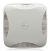
Figure 1
Front Panel of the W-7005 Controller
Figure 2
Back Panel of the W-7005 Controller
Ethernet Ports
The W-7005 controller is equipped with four 10/100/1000BASE-T Gigabit Ethernet
ports (0 to 3). Gigabit Ethernet uses all eight wires and each pair is bi-directional,
which means, the same pair is used for both data transmission and data reception.
Figure 3
illustrates the Gigabit Ethernet port pin-out for an RJ-45 connector. The
pins paired on a 10/100/1000BASE-T Gigabit Ethernet port are: 1/2, 3/6, 4/5, and 7/8.
Figure 3
Gigabit Ethernet Port Pin-Out
Ethernet Port LEDs
Each 10/100/1000BASE-T Ethernet port is equipped with two LEDs that allow basic
monitoring of link/port status and activity.
LINK/ACT
: Placed on the left side of the port, this LED displays the link status
and activity of the port.
STATUS
: Placed on the right side of the port, this LED displays the status of the
port based on the CLI.
The following table describes the LED behavior for each mode:
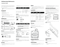
Console Port
The serial console port allows connecting the controller to a serial terminal or a
laptop for direct local management. This port is an RJ-45 female connector with
pinouts described in
Figure 4
. Connect it directly to a terminal or terminal server
using an Ethernet cable.
Figure 4
Serial Console Port Pin-Out
The communication settings for the Console port are shown in the following table:
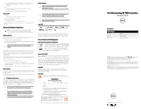
Serial Console Port Adaptor
A modular adaptor can be used to convert the female RJ-45 connector to a male DB9
connector. See
Figure 5
for complete details.
Figure 5
RJ-45 (Female) to DB9 (Male) Modular Adapter Conversion
Mini-USB Console Connector
The W-7005 controller is equipped with one Mini-USB (type B) connector that
provides console access for direct local access. If both Mini-USB and RJ-45 Console
ports are connected, the Mini-USB connection takes precedence over the RJ-45
Console connection.
Mini-USB Driver
To use the Mini-USB console port, install the Dell Mini-USB driver on the computer
that will manage the W-7005 controller. The driver is available on
download.dell-
pcw.com
under Tools & Resources.
USB Interface
The W-7005 controller is equipped with one USB 2.0 interface. A USB storage device
can be used to save and upload configurations to the controller.
Power and Status LEDs
The front panel also includes power and status LEDs that provide basic monitoring
of the overall status of the W-7005 controller
Kensington Security Slot
The W-7005 controller is equipped with a Kensington security slot for additional
security.
DC Power Socket
The AC-DC adapter kit with the following specification is used to power the W-7005
controller:
12V/ 2A power interface
Center-positive 1.7/4.0 mm circular plug, 9.5 mm length
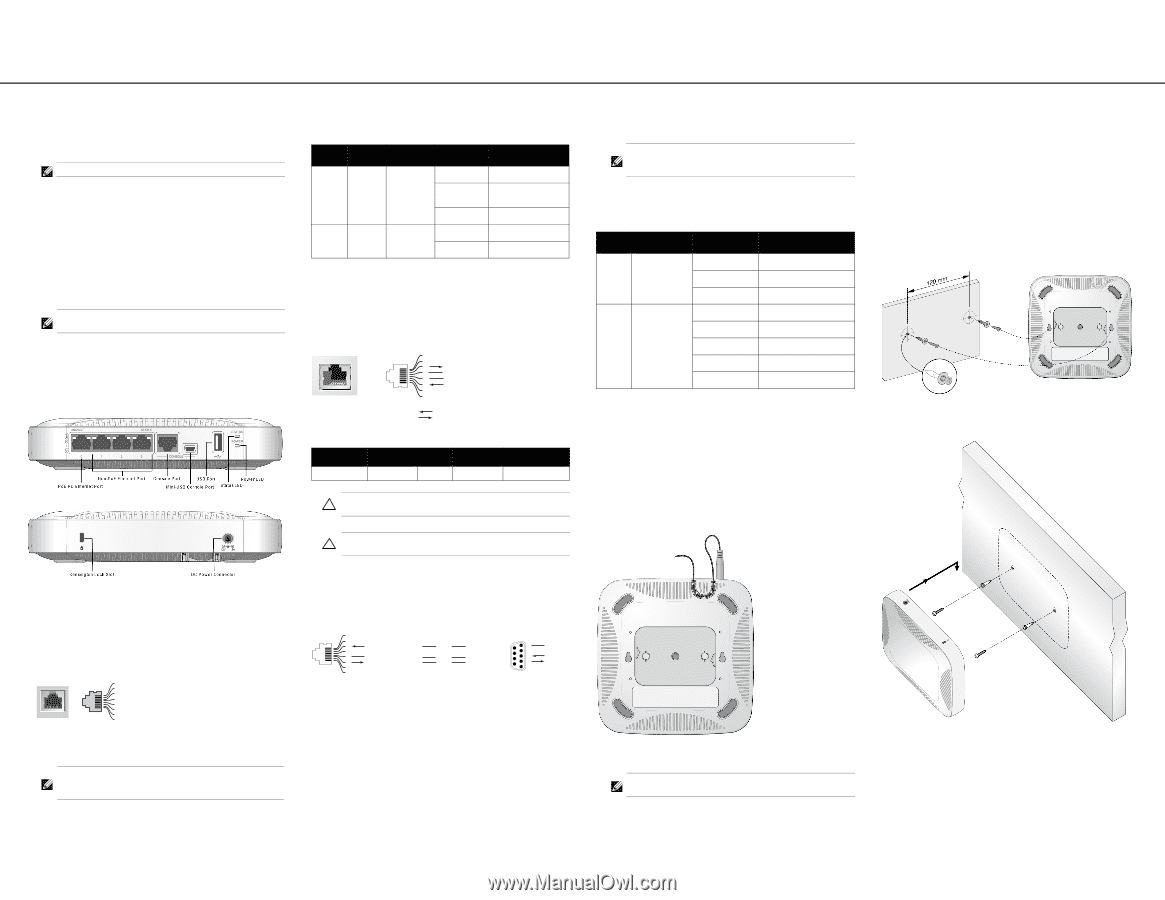
Make sure to securely route the DC cable through the slot provided. See
Figure 6
.
Figure 6
DC Cable Routing Slot
Installing the W-7005 Controller
Installation Recommendations
For proper air circulation, leave at least 10 cm (4 inches) clearance for the vents
on the left, right, front, and rear side of the controller.
Leave additional space in front and rear side of the controller to access power
cords, network cables, and indicator LEDs.
Avoid placing anything that covers the vents on top of the controller. Covering
the vents can lead to overheating of the controller.
Avoid placing this controller on any other device because the heat dissipated from
the other device may overheat the controller.
Installation Using the Integrated Wall-Mounting Slots
The keyhole-shaped slots on the bottom of the controller can be used to attach the
device upright (front port facing downwards) to an indoor wall or shelf.
Since the ports are on the front of the device, make sure to mount the controller in
such a way that there is a clear path to the Ethernet port, such as a pre-drilled hole in
the mounting surface.
1.
At the mounting location, install two screws on the wall or shelf, 120 mm apart. If
you are attaching the device to drywall, it is recommended that you use
appropriate wall anchors (not included). See
Figure 7
.
Figure 7
Mounting Using the Integrated Wall-Mounting Slots
2.
Align the mounting slots on the bottom of the controller over the screws and slide
the unit into place. See
Figure 8
.
Figure 8
Wall Mounting W-7005
Product Specifications
Physical
Device Dimensions (HxWxD): 4.09 cm x 20 cm x 20 cm
Device Weight: 2.03 lbs (0.92 kg)
Electrical
Ethernet:
4 x 10/100/1000BASE-T auto-sensing Ethernet RJ-45 Interfaces
MDI/MDX
Note:
The W-7005 controller requires Dell Networking W-Series AOS 6.4.1.0 or later.
Note:
Optional accessories are available for use with the W-7005 controller and are
sold separately. Contact your Dell sales representative for details and assistance.
Note:
In the W-7005 controller, the orange numbering on port 0 indicates that it is a
PoE powered device (PoE-PD) port and the gray numbering on ports 1, 2, and 3
indicate that they are non-PoE ports.
1000Base-T Gigabit
Ethernet Port
RJ-45 Female
Pin-Out
Signal Name
1
2
3
4
5
6
7
8
BI_DC+
BI_DC-
BI_DD+
BI_DD-
BI_DA+
BI_DA-
BI_DB+
BI_DB-
Function
Bi-directional pair +C
Bi-directional pair -C
Bi-directional pair +D
Bi-directional pair -D
Bi-directional pair +A
Bi-directional pair -A
Bi-directional pair +B
Bi-directional pair -B
LED
Function
Mode
Indicator
Status
LINK/ACT
Link status
N/A
Green (Solid)
Link has been established
Green (Blinking)
Port is transmitting or
receiving data
Off
No link on port
STATUS
Port status
Speed
Green (Solid)
1000 Mbps
Off
10/100 Mbps
Baud Rate
Data Bits
Parity
Stop Bits
Flow Control
9600
8
None
1
None
Caution:
The CONSOLE port is compatible only with RS-232 devices. Non-RS-232
devices, such as APs, are not supported.
Caution:
Do not connect the Console port to an Ethernet switch or a PoE power
source. This may damage the controller.
Serial
Console Port
1
2
3
4
5
6
7
8
TxD
GND
RxD
RJ-45 Female
Pin-Out
Direction
Input
Output
GND
3
4
5
2
5
6
3
RJ-45
DB-9
Internal
Connections
TxD
GND
RxD
1
2
3
4
5
6
7
8
TxD
GND
RxD
RJ-45 Female
Pin-Out
DB-9 Male
Pin-Out
TxD
RxD
Ground
5
4
3
2
1
9
8
7
6
Note:
If the W-7005 controller is powered from IEEE 802.3at PSE, then the USB port
remains enabled. If the W-7005 controller is powered from IEEE 802.3af PSE, then the
USB port is automatically disabled.
LED
Function
Indicator
Status
Power
System powers
Green (Solid)
Powered from DC adapter
Amber (Solid)
Powered from PoE source
Off
Power Off
Status
System status
Green (Solid)
Operational
Green (Blinking)
Device is loading software
Amber (Blinking)
Major Alarm
Amber (Solid)
Critical Alarm
Off
No power
Note:
Service to all Dell Networking products should be performed by trained service
personnel only.