EVGA 112-CK-NF75-K1 Installation Guide
EVGA 112-CK-NF75-K1 Manual
 |
View all EVGA 112-CK-NF75-K1 manuals
Add to My Manuals
Save this manual to your list of manuals |
EVGA 112-CK-NF75-K1 manual content summary:
- EVGA 112-CK-NF75-K1 | Installation Guide - Page 1
- EVGA 112-CK-NF75-K1 | Installation Guide - Page 2
, Pentium EE, Pentium, and Celeron Socket 775 CPU's. (up to 1066Mhz FSB on 610i motherboards) ‰ Cooling fan and heat sink for the microprocessor ‰ System memory support: Supports single channel DDR2 533/667/800, (800MHz not supported on 610i Motherboards ) ‰ Power Supply The power supply requirement - EVGA 112-CK-NF75-K1 | Installation Guide - Page 3
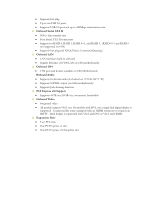
1394 • 1394 port and header available on 630i Motherboards Onboard Audio • Supports 8-channel audio (6-channel on 112-CK-NF71-T1) • Supports S/PDIF output (on 630i motherboards) • Supports Jack-Sensing function ‰ PCI Express x16 Support • Supports 4 GB/sec (8 GB/sec concurrent) bandwidth ‰ Onboard - EVGA 112-CK-NF75-K1 | Installation Guide - Page 4
section will guide you through the installation of the motherboard. The topics covered in this section are: ‰ Preparing the motherboard • Installing the CPU • Installing the CPU fan • Installing the memory ‰ Installing the motherboard ‰ Connecting cables and setting switches Safety Instructions To - EVGA 112-CK-NF75-K1 | Installation Guide - Page 5
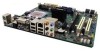
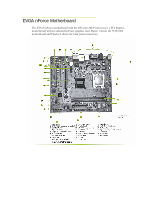
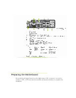
EVGA nForce Motherboard The EVGA nForce motherboard with the 600 series MCP processor is a PCI Express motherboard with an onboard GeForce graphics card. Figure 1 shows the 7150/630i motherboard and Figures 2 shows the back panel connectors. - EVGA 112-CK-NF75-K1 | Installation Guide - Page 6
Preparing the Motherboard The motherboard shipped in the box does not contain a CPU or memory. You need to purchase a CPU, a CPU heat sink/fan assembly, and memory module(s) to complete this installation. - EVGA 112-CK-NF75-K1 | Installation Guide - Page 7
you remove the CPU, you have a motherboard. Follow the instruction that came with your fan assembly. Be sure that the fan orientation is correct for your chassis type and your fan assembly. Installing Memory DIMMs Your new motherboard has two 1.8V 240-pin slots for DDR2 memory. These slots support - EVGA 112-CK-NF75-K1 | Installation Guide - Page 8
Also make sure the CPU Fan assembly is aligned with the vents on the covers. Installing the I/O Shield The motherboard kit comes with an according to the fan assembly instruction. 5. Secure the motherboard with a minimum of six screws. Power Connections This motherboard requires an ATX power supply - EVGA 112-CK-NF75-K1 | Installation Guide - Page 9
8-pin ATX 12V power connection, is used to provide power to the CPU. Align the pins to the connector and press firmly until seated. It connector is used to connect the Serial ATA II device to the motherboard. These connectors support the thin Serial ATA II cables for primary storage devices. The - EVGA 112-CK-NF75-K1 | Installation Guide - Page 10
a USB bracket. Audio The audio connector supports the HD audio standard. Most cases come - Analog port 2 - left channel (Headphone) 10 SENSE2_RETURN - Jack CPU fan cable can be either a 3-pin or a 4-pin connector. Connect a 3-pin connector to pins 1, 2, and 3 on the motherboard connector. CPU - EVGA 112-CK-NF75-K1 | Installation Guide - Page 11
a full list of PCI Express x16 graphics card supported by this motherboard, go to www.evga.com/products/. PCI Slots The two PCI slots support many expansion cards such as a LAN card, any hardware configurations in the BIOS setup if needed. Boot from your OS disk. Once your operating system is installed - EVGA 112-CK-NF75-K1 | Installation Guide - Page 12
Keyboard Init Initialized the mouse Check Check the integrity of the ROM,BIOS and message EEPROM Check Flash type and copy flash Write/erase routines Test and Reset CMOS Load Chipset Defaults Initialize onboard clock generator CPU ID and initialize L1/L2 cache Initialize first 120 interrupt vectors - EVGA 112-CK-NF75-K1 | Installation Guide - Page 13
registers Init PNP Shadow system/video BIOS Gen Init onboard clock generator and sensor Setup BIOS DATA AREA (BDA) Chipset programming and CPU Speed detect Initialize Video Test Video Memory and display Logos Early Keyboard Reset Test DMA channel 0 Test DMA channel 1 Test DMA Page Registers Test - EVGA 112-CK-NF75-K1 | Installation Guide - Page 14
4A Reserved 4B Reserved 4C Reserved 4D Reserved 4E Init APIC 4F Reserved 50 USB init Initialize 51 Reserved 52 Memory Test 53 Reserved 54 Reserved 55 CPU display 56 Reserved 57 PnP Init 58 Reserved 59 Setup Virus 5A Reserved 5B Awdflash Load 5C Reserved 5D - EVGA 112-CK-NF75-K1 | Installation Guide - Page 15
Reserved HDD Write Protect Reserved Reserved POST error check 80 Reserved 81 Reserved 82 Security 85 USB Final Init 86 Reserved 87 Reserved 88 Reserved 89 Setup ACPI tables 8A Reserved 8B C0 Base CPU test Description Initialize floppy disk drive Install FDD and setup BIOS data - EVGA 112-CK-NF75-K1 | Installation Guide - Page 16
Code(hex) C1 C2 C3 C4 C5 C6 FF Name Memory Presence Early Memory Extend Memory Special Display Early Shadow Cache presence Boot Description Base memory detect Board Initialization Turn on extended memory, cache initialization First display initialization Early shadow enable for fast boot External - EVGA 112-CK-NF75-K1 | Installation Guide - Page 17
-
 1
1 -
 2
2 -
 3
3 -
 4
4 -
 5
5 -
 6
6 -
 7
7 -
8
-
9
-
10
-
11
-
12
-
13
-
14
-
15
-
16
-
17
 |
 |
