EVGA Z68 SLI Micro User Guide
EVGA Z68 SLI Micro Manual
 |
View all EVGA Z68 SLI Micro manuals
Add to My Manuals
Save this manual to your list of manuals |
EVGA Z68 SLI Micro manual content summary:
- EVGA Z68 SLI Micro | User Guide - Page 1
- EVGA Z68 SLI Micro | User Guide - Page 2
EVGA Z68/P67 Motherboard - EVGA Z68 SLI Micro | User Guide - Page 3
EVGA Z68/P67 Motherboard Table of Contents - EVGA Z68 SLI Micro | User Guide - Page 4
EVGA Z68/P67 Motherboard - EVGA Z68 SLI Micro | User Guide - Page 5
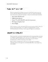
EVGA Z68/P67 Motherboard Thank you for purchasing the EVGA Z68/P67 Motherboard. This board is based off of the new Intel Z68/P67 chipset with native support for SATA III/6G for the performance you demand, delivered when you need it. As always this board comes with the added bonus of EVGA's industry - EVGA Z68 SLI Micro | User Guide - Page 6
to install and connect your new EVGA Z68/P67 Motherboard. However, it does not contain the following items that must be purchased separately to make the motherboard functional. Intel Socket 1155 Processor DDR3 System Memory Socket 775 or 1155/1156 CPU cooler for the processor PCI Express - EVGA Z68 SLI Micro | User Guide - Page 7
EVGA Z68/P67 Motherboard Size EATX form factor of 12 inches x 10.3 inches Microprocessor support Intel Socket 1155 Processor Operating systems: Supports Windows XP/Vista/7 32 and 64 bit Contains Intel Z68/P67 chipset System Memory support Supports Dual channel DDR3-2133+. Officially - EVGA Z68 SLI Micro | User Guide - Page 8
EVGA Z68/P67 Motherboard SATA ports up to 3.0 Gb/s (300 M/s) data transfer rate SATA ports up to 6.0 Gb/s (600 M/s) data transfer rate Support for RAID 0, RAID 1, RAID 0+1, RAID5 and RAID 10 ESATA (optional) Onboard LAN Supports 10/100/1000 Mbit/sec Ethernet Onboard IEEE 1394a (Firewire) - EVGA Z68 SLI Micro | User Guide - Page 9
are included with the EVGA Z68/P67 Motherboard: The EVGA Z68/P67 Motherboard This PCI-E motherboard contains the Intel Z68/P67 chipset and is SLI-ready. - Visual Guide Helps to quickly and visually guide you through the hardware installation of the motherboard. - I/O Shield Installs in the system - EVGA Z68 SLI Micro | User Guide - Page 10
EVGA Z68/P67 Motherboard - I/O Shield Fan (Optional) Exhausts Air from the IO Shield out of the rear of the case. Attaches to IO Shield. - 2-Port SATA Power Cables Allows a Molex power connector to adapt to a SATA power connector. - 2-Port USB 2.0 / 1394a Firewire Bracket Provides two additional USB - EVGA Z68 SLI Micro | User Guide - Page 11
EVGA Z68/P67 Motherboard - EVGauge (Optional) Analog Gauge that represents your CPU frequency in real time. - ECP Panel (Optional) Allows monitoring of post codes and remote control of PCIe slot disable, voltages and CMOS reset all on one bay mounted panel. - Installation CD Contains drivers and - EVGA Z68 SLI Micro | User Guide - Page 12
EVGA Z68/P67 Motherboard This section will guide you through the installation of the motherboard. The topics covered in this section are: Preparing the motherboard Installing the CPU Installing the CPU fan Installing the memory Installing the motherboard Connecting cables To reduce the - EVGA Z68 SLI Micro | User Guide - Page 13
EVGA Z68/P67 Motherboard Be very careful when handling the CPU. Hold the processor only by the edges and do not touch the bottom of the processor. Use the following procedure to install the CPU onto the motherboard: Unhook the socket lever by pushing down and away from the socket. Pull the socket - EVGA Z68 SLI Micro | User Guide - Page 14
EVGA Z68/P67 Motherboard Align the notches in the processor with the notches on the socket. Lower the processor straight down into the socket with out tilting or sliding it into the socket. Note: Make sure the CPU is fully seated and level in the socket. Close the load plate over the CPU and - EVGA Z68 SLI Micro | User Guide - Page 15
EVGA Z68/P67 Motherboard Your new motherboard has four 240-pin slots for DDR3 memory. These slots support 1GB, 2GB and 4GB DDR3 DIMMs. There must be at least one memory slot populated to ensure normal operation. Use the following the recommendations for installing memory. (See Figure 1 on page for - EVGA Z68 SLI Micro | User Guide - Page 16
EVGA Z68/P67 Motherboard The sequence of installing the motherboard into a system case depends on the chassis you are using and if you are replacing an existing motherboard or working with an empty system case. Determine if it would be easier to make all the connections prior to this step or to - EVGA Z68 SLI Micro | User Guide - Page 17
EVGA Z68/P67 Motherboard Most system cases have a base with mounting studs or spacers to allow the motherboard to be secured to the chassis and help to prevent short circuits. If there are studs that do not align with a mounting hole on the motherboard, it is recommended that you remove that stud to - EVGA Z68 SLI Micro | User Guide - Page 18
EVGA Z68/P67 Motherboard Expansion slots CMOS Clear Button PW1 is the main power supply connector located along the edge of the board next to the DIMM slots. Make sure that the power supply cable and pins are properly aligned with the connector on the motherboard. Firmly plug the power supply - EVGA Z68 SLI Micro | User Guide - Page 19
EVGA Z68/P67 Motherboard PW12-1 & PW12-2, the 8-pin ATX 12V power connection, is used to provide power to the CPU. Align the pins to the connector and press firmly until seated. The BIOS Select Switch is located directly to the right of the PC speaker on the lower edge of the mainboard. This jumper - EVGA Z68 SLI Micro | User Guide - Page 20
EVGA Z68/P67 Motherboard The front panel header on this motherboard is one connector used to connect the following four cables. (see Table 2 for pin definitions): PWRLED Attach the front panel power LED cable to these two pins of the connector. The Power LED indicates the system's status. When - EVGA Z68 SLI Micro | User Guide - Page 21
EVGA Z68/P67 Motherboard The IEEE 1394a expansion cable bracket is provided in the box but if you do not require the additional external connections, you do not need to install it. Secure the bracket to either the front or rear panel of the system case (not all system cases are equipped with the - EVGA Z68 SLI Micro | User Guide - Page 22
EVGA Z68/P67 Motherboard This motherboard contains six (6) USB 2.0 ports that are exposed on the rear panel of the chassis (Figure 2). The motherboard also contains two 10-pin internal header connectors onboard that can be used to connect an optional external bracket containing up to four (4) USB - EVGA Z68 SLI Micro | User Guide - Page 23
EVGA Z68/P67 Motherboard The audio connector supports HD audio standard and provides two kinds of audio output choices: the Front Audio and the Rear Audio. The Front Audio supports re-tasking function. Table 5. Front Audio Connector Connector Front Audio Connector 10 9 8 7 6 5 4 3 2 1 - EVGA Z68 SLI Micro | User Guide - Page 24
EVGA Z68/P67 Motherboard There are PCI-E x1 slots that are designed to accommodate less bandwidthintensive cards, such as a modem, sound or LAN card. These PCI-E slots are reserved for Graphics Cards and PCI-E x1, x4, x8 and x16 devices. The design of this motherboard supports multiple Graphics Card - EVGA Z68 SLI Micro | User Guide - Page 25
EVGA Z68/P67 Motherboard These onboard buttons include RESET, POWER and Clear CMOS. These functions allow you to easily reset the system, turn on/off the system, or clear the CMOS. The motherboard uses the CMOS RAM to store all the set parameters. The CMOS can be cleared by pressing the Clear CMOS - EVGA Z68 SLI Micro | User Guide - Page 26
EVGA Z68/P67 Motherboard Provides two-digit POST codes to show why the system may be failing to boot. It is useful during troubleshooting situations. This Debug LED will also display current CPU socket temperatures after the system has fully booted into the Operating System. Debug LED with CPU - EVGA Z68 SLI Micro | User Guide - Page 27
and drivers: Chipset Drivers Audio Drivers RAID Drivers LAN Drivers Matrix Storage USB 3.0 Drivers EVGA E-LEET User's Manual 1. Insert the EVGA Z68/P67 installation CD for the motherboard included in the kit. 2. The CD will autorun, install the drivers and utilities listed on - EVGA Z68 SLI Micro | User Guide - Page 28
EVGA Z68/P67 Motherboard This section provides the AMI POST Codes (Table 6) for the EVGA Z68/P67 Motherboard during system boot up. The POST Codes are displayed on the Debug LED readout located directly onboard the motherboard. This Debug LED will also display current CPU temperatures after the - EVGA Z68 SLI Micro | User Guide - Page 29
EVGA Z68/P67 Motherboard 1C 1D- OEM pre-memory initialization codes 2A 2B Memory initialization. Serial Presence Detect (SPD) data reading 2C Memory initialization. Memory presence detection 2D Memory initialization. Programming memory timing information 2E Memory initialization. Configuring memory - EVGA Z68 SLI Micro | User Guide - Page 30
EVGA Z68/P67 Motherboard is failed 5A Internal CPU error 5B reset PPI is not available 5C- Reserved for future AMI error codes 5F E0 S3 Resume is stared (S3 Resume PPI is called by the DXE IPL) E1 S3 Boot Script execution E2 Video repost E3 OS S3 wake vector call E4- Reserved for future AMI progress - EVGA Z68 SLI Micro | User Guide - Page 31
EVGA Z68/P67 Motherboard 71 South Bridge DXE SMM initialization is started 72 South Bridge devices initialization 73- South Bridge DXE Initialization (South Bridge 77 module specific) 78 ACPI module initialization 79 CSM initialization 7A- Reserved for future AMI DXE codes 7F 80- OEM DXE - EVGA Z68 SLI Micro | User Guide - Page 32
EVGA Z68/P67 Motherboard AD Ready To Boot event AE Legacy Boot event AF Exit Boot Services event B0 Runtime Set Virtual Address MAP Begin B1 Runtime Set Virtual Address MAP End B2 Legacy Option ROM Initialization B3 System Reset B4 USB hot plug B5 PCI bus hot plug B6 Clean-up of NVRAM B7 - EVGA Z68 SLI Micro | User Guide - Page 33
EVGA Z68/P67 Motherboard 1337 - This is reserved for EVGA level elite AC - Alternating Current ACPI - Advanced Configuration and Power Interface AFR - Alternate Frame Rendering APIC - Advanced Programmable Interrupt Controller ACPI - Advanced Configuration and Power Interface BCLK - Base Clock (or - EVGA Z68 SLI Micro | User Guide - Page 34
EVGA Z68/P67 Motherboard FSB - Front Side Bus - For The Win! GHz - Gigahertz GPU - Graphics Processing Institute of Electrical and Electronics Engineers IGP - Integrated Graphics Processors IMC - Integrated memory controller IRQ - Interrupt Request JBOD - Just a Bunch of Disks JEDEC - Joint - EVGA Z68 SLI Micro | User Guide - Page 35
Peripheral Component Interconnect PCIe - Peripheral Component Interconnect Express PCI-x - Peripheral Component Interconnect Extended POST - Power on Control Protocol/Internet Protocol USB - Universal Serial Bus VDroop - V-core Voltage Drop VGA - Video Graphics Array EVGA Z68/P67 Motherboard - EVGA Z68 SLI Micro | User Guide - Page 36
EVGA Z68/P67 Motherboard instructions shielded service names may be trademarks or service marks of others. EVGA owned, controlled by price of the materials (or replacement of the materials at EVGA Corporation's option). All information furnished is believed to be accurate and reliable. However, EVGA
-
 1
1 -
 2
2 -
 3
3 -
 4
4 -
 5
5 -
 6
6 -
 7
7 -
8
-
9
-
10
-
11
-
12
-
13
-
14
-
15
-
16
-
17
-
18
-
19
-
20
-
21
-
22
-
23
-
24
-
25
-
26
-
27
-
28
-
29
-
30
-
31
-
32
-
33
-
34
-
35
-
36
 |
 |