Electrolux EFMG627UIW Wiring Diagram English
Electrolux EFMG627UIW Manual
 |
View all Electrolux EFMG627UIW manuals
Add to My Manuals
Save this manual to your list of manuals |
Electrolux EFMG627UIW manual content summary:
- Electrolux EFMG627UIW | Wiring Diagram English - Page 1
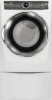
Dryer Tech Data Sheet 1 Safety items throughout this manual are labeled with a WARNING or CAUTION based on the or property damage. CAUTION Unless otherwise directed, disconnect electrical current before servicing. 1 2 3 Rotary Dial Cycle Select Dryer User Interface 4 5 Canada 1-800-265-8352 - Electrolux EFMG627UIW | Wiring Diagram English - Page 2
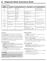
2 Diagnostic Mode Tests/Demo Mode Diagnostic Mode Tests Mode Number pre-test (select models) Test Name Components Under Test Test Conditions Displayed Feedback Lights, Buttons LED indicators LCD screen Button response Motor, NO HEAT, HUM ON Motor, NTC1 ctrl heater, HUM ON, NTC1 temp on - Electrolux EFMG627UIW | Wiring Diagram English - Page 3
safe relay closed, motor sensing detects voltage on motor 1. Motor short circuit to ground (motor or wiring) 2. Electrical noise 3. Line safe relay problem (main board failure) 4. Motor relay open or short Motor relay driven but start sensing not congruent 1. Motor fault 2. Main board fault Drum - Electrolux EFMG627UIW | Wiring Diagram English - Page 4
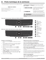
4 Fiche technique de la sécheuse Ce manuel est destiné aux techniciens de service qualifiés seulement. Table des matières Fiche technique de la sécheuse 4 Essais en est désactivée « », ou débranchez l'appareil. Aux É.-U. : 1-877-435-3287 www.electroluxappliances.com Au Canada : 1-800-265-8352 - Electrolux EFMG627UIW | Wiring Diagram English - Page 5
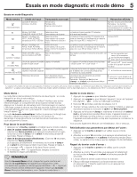
Essais en mode diagnostic et mode démo 5 Essais en mode Diagnostic Mode numéro Libellé de l'essai Composants sous essai Conditions d'essai Rétroaction affichée essai préliminaire Lampes et témoins lumineux, boutons Témoins DEL Panneau ACL Réponse des boutons Numéro de la touche enfoncée. - Electrolux EFMG627UIW | Wiring Diagram English - Page 6
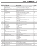
6 Codes d'erreur de la sécheuse Codes d'erreur de la sécheuse Erreur code 34 35 36 41 42 51 52 53 54 61 63 64 65 67 71 72 73 74 91 92 93 94 97 9C 9E H1/B1 H2/B2 H3/B3 H4/B4 HA/BD HE / BE HF/BF F1 F6 Description des erreurs Raisons possibles Affichage signalement Les valeurs de capteur - Electrolux EFMG627UIW | Wiring Diagram English - Page 7
7 Pruebas del modo de diagnóstico 8 Códigos de error de la secadora 9 Esquema de cableados 10 Los elementos de seguridad de este manual están marcados con la etiqueta ADVERTENCIA o PRECAUCIÓN dependiendo del tipo de riesgo según se describe a continuación: Este símbolo alerta de situaciones que - Electrolux EFMG627UIW | Wiring Diagram English - Page 8
8 Pruebas del modo de diagnóstico Pruebas del modo de diagnóstico Número de modo Nombre de la prueba Componentes sujetos a prueba Condiciones de la prueba Respuesta mostrada pre-prueba Luces, botones Indicadores LED Pantalla LCD Botón de respuesta Número de la tecla pulsada. Nota: este nú - Electrolux EFMG627UIW | Wiring Diagram English - Page 9
Códigos de error de la secadora 9 Códigos de error de la secadora Código Descripción del error de error Posible causa Pantalla notificación 34 Los valores del sensor capacitivo leídos por el Compruebe el cableado entre el control principal y el conjunto del sensor capacitivo No control - Electrolux EFMG627UIW | Wiring Diagram English - Page 10
PELIGRO DE DESCARGA ELÉCTRICA To avoid electrical shock, disconnect Pour éviter tout choc électrique, débranchez Para evitar descargas eléctricas, desconecte electrical current before servicing. le courant électrique avant l'entretien. la corriente eléctrica antes de dar servicio. - Electrolux EFMG627UIW | Wiring Diagram English - Page 11
PELIGRO DE DESCARGA ELÉCTRICA To avoid electrical shock, disconnect Pour éviter tout choc électrique, débranchez Para evitar descargas eléctricas, desconecte electrical current before servicing. le courant électrique avant l'entretien. la corriente eléctrica antes de dar servicio. - Electrolux EFMG627UIW | Wiring Diagram English - Page 12
PELIGRO DE DESCARGA ELÉCTRICA To avoid electrical shock, disconnect Pour éviter tout choc électrique, débranchez Para evitar descargas eléctricas, desconecte electrical current before servicing. le courant électrique avant l'entretien. la corriente eléctrica antes de dar servicio. - Electrolux EFMG627UIW | Wiring Diagram English - Page 13
PELIGRO DE DESCARGA ELÉCTRICA To avoid electrical shock, disconnect Pour éviter tout choc électrique, débranchez Para evitar descargas eléctricas, desconecte electrical current before servicing. le courant électrique avant l'entretien. la corriente eléctrica antes de dar servicio. - Electrolux EFMG627UIW | Wiring Diagram English - Page 14
14 Notes | Remarques | Notas - Electrolux EFMG627UIW | Wiring Diagram English - Page 15
Notes | Remarques | Notas 15 - Electrolux EFMG627UIW | Wiring Diagram English - Page 16
16 Notes | Remarques | Notas
-
 1
1 -
 2
2 -
 3
3 -
 4
4 -
 5
5 -
 6
6 -
 7
7 -
8
-
9
-
10
-
11
-
12
-
13
-
14
-
15
-
16
 |
 |
1
Canada 1-800-265-8352
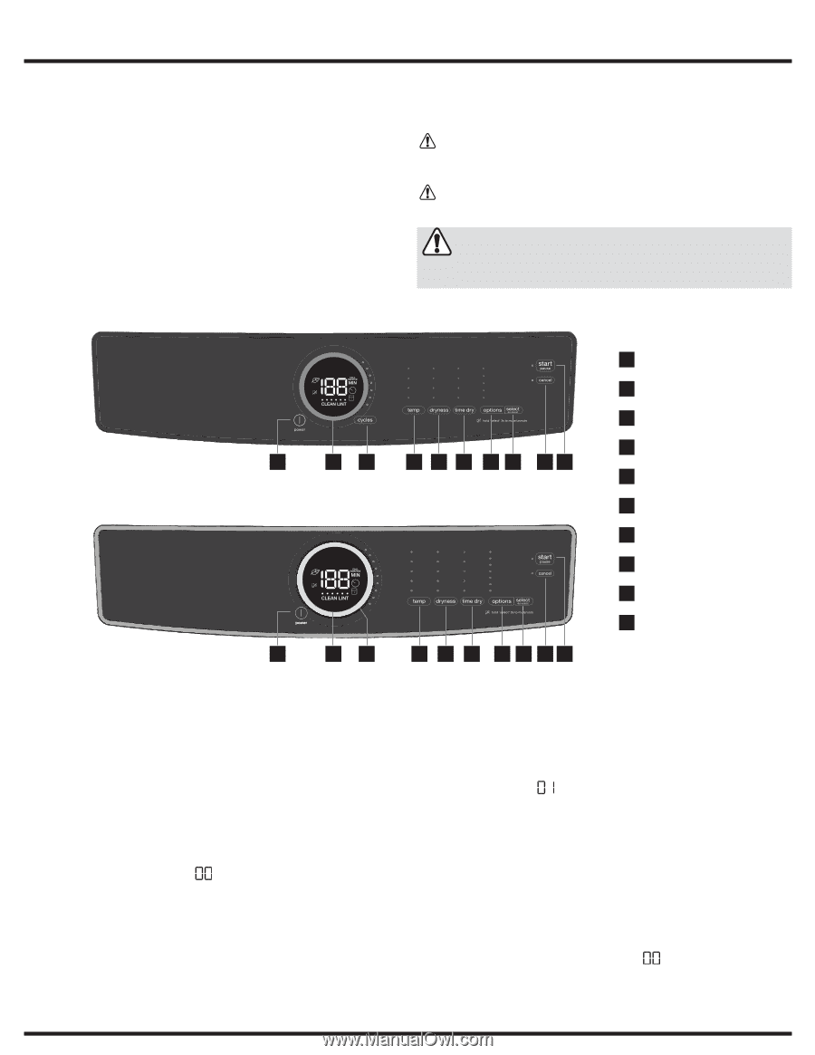
Push Button Cycle Select Dryer User Interface
Rotary Dial Cycle Select Dryer User Interface
A11199903
(1901)
USA 1-877-435-3287
This information is intended for Qualified Technicians Only.
Table of Contents
Entering Diagnostic Mode:
1.
Press
power
and look for console light up.
2.
Rotate cycle selector ring (on some models) or repeatedly press
cycle button (on other models) to set cycle to
normal
.
3.
Press the
start
button.
4.
Power off machine by pressing the
power
button.
5.
Power on machine by pressing the
power
button again.
6.
Within
10
seconds, simultaneously hold
temp + select (set)
buttons together for
3
seconds.
7.
Diagnostic Mode
is active when LED’s start blinking in sequence.
This is the pre-test position “
”
, which tests the lights and buttons.
8.
Press the
start
button.
Safety items throughout this manual are labeled with a
WARNING
or
CAUTION
based on the risk type as described below:
This symbol alerts you to situations that may
cause bodily injury or property damage.
This symbol alerts you to situations that may
cause serious body harm, death or property
damage.
Dryer Tech Data Sheet
Scrolling through Diagnostic Mode tests:
Tests are selected by using the same method to select cycles.
See
Diagnostic Mode Tests Table.
For push button cycle select dryer:
Press and hold the
cycle
button for
2
seconds. The unit will advance to
the first test; and flash
“
”
on the display. Press the
cycle
button to
advance to the following test. Press the
temp
button to go back to the
previous test.
For rotary dial cycle select dryer:
Use knob to advance to the first test by rotating clockwise. Turn knob
counterclockwise to navigate previous tests.
Test sequence numbers are briefly displayed when each test is selected.
The displayed test numbers also correspond to the selector LEDs to
the right of the numeric display; beginning with the top LED, following
downward.
Exiting Diagnostic Mode:
Hold the
power
key for
3
sec, when not in “
”
test step
Lights/Buttons, or unplug the unit.
www.electroluxappliances.com
CAUTION
WARNING
CAUTION
Unless otherwise directed, disconnect electrical current before
servicing.
Dryer Tech Data Sheet
................................................................
1
Diagnostic Mode Tests/Demo Mode
...........................................
2
Dryer Error Codes
.......................................................................
3
Wiring Diagrams
.......................................................................
10
1
power
2
cycle status display
3
cycle selector
4
temperature
5
dryness (dry level)
6
time dry (dry time)
7
options
8
select (set)
9
cancel
10
start / pause
2
7
1
6
3
8
5
4
9
10
2
7
1
6
3
9
8
5
4
10