Electrolux EW36CC55GW Installation Instructions (All Languages)
Electrolux EW36CC55GW - 36in Electric Cooktop Manual
 |
UPC - 057112096797
View all Electrolux EW36CC55GW manuals
Add to My Manuals
Save this manual to your list of manuals |
Electrolux EW36CC55GW manual content summary:
- Electrolux EW36CC55GW | Installation Instructions (All Languages) - Page 1
COOKTOP INSTALLATION INSTRUCTIONS Canada INSTALLATION AND SERVICE MUST BE PERFORMED BY A QUALIFIED INSTALLER. IMPORTANT: SAVE FOR LOCAL ELECTRICAL INSPECTOR'S USE. READ AND SAVE THESE INSTRUCTIONS mODEL 30'' Ceramic Model 36'' Ceramic Model mODEL 30'' Ceramic Model 36'' Ceramic Model A. WIDTH 30 - Electrolux EW36CC55GW | Installation Instructions (All Languages) - Page 2
the cooktop should be avoided. If cabinet storage is provided, risk can be reduced by installing a range hood that projects horizontally a minimum of 5" (12.7 cm) beyond the bottom of the cabinets. Model 30'' (76.2 cm) 36'' (91.4 cm) J 7½'' (19.1 cm) 7½'' (19.1 cm) Figure 2 - COUNTERTOP CUTOUT - Electrolux EW36CC55GW | Installation Instructions (All Languages) - Page 3
will overlap cutout (minimum) edges by 1" (2.5cm) Use 3/4" (1.9 cm) plywood, installed on two runners, flush with toe plate. Base must be capable of supporting 150 pounds (68 kg) for 27" models and 200 pounds (90 kg) for 30" models. 4 1/2" (11.5 cm) Max.* * If no cooktop is installed directly over - Electrolux EW36CC55GW | Installation Instructions (All Languages) - Page 4
with your Use and Care Guide for future reference. IMPORTANT SAFETY INSTRUCTIONS • Be sure your cooktop is installed and grounded properly by a qualified installer or service technician. • These cooktops must be electrically grounded in accordance with local codes or, in their absence, with - Electrolux EW36CC55GW | Installation Instructions (All Languages) - Page 5
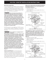
ELECTRIC COOKTOP INSTALLATION INSTRUCTIONS Electrical connection It is the responsibility and obligation of the consumer to contact a qualified installer to assure that the electrical installation is adequate and is in conformance with the National Electrical Code ANSI/NFPA No. 70-latest edition, - Electrolux EW36CC55GW | Installation Instructions (All Languages) - Page 6
Canadian Electrical Code, Part 1 in Canada (see Figure 7). Cooktop Countertop Nylon spacer Retainer bracket Figure 7 6 Nylon spacers Position brackets on unit cutout center line 2 Retainer brackets Figure 8 Granite countertop Installation Kit A Granite Countertop Installation kit # 903061 - Electrolux EW36CC55GW | Installation Instructions (All Languages) - Page 7
eléctrica va a ser instalada sobre un horno de empotrar. Parte delantera 3 1/8 (7,9) G Mostrador Parte trasera 6 ½ (16,5) Mostrador 4 ½ (11,4) 6 7/8 (17,5) Vista de lado mODELO Modelo 30'' Modelo 36'' mODELo Modelo 30'' Modelo 36'' DIMENSIONES de la estufa A. anchura B. profundidad - Electrolux EW36CC55GW | Installation Instructions (All Languages) - Page 8
un armario, se pueden reducir los riesgos instalando una campana que se extienda horizontalmente en un mínimo de 5" (12.7 cm) por sobre la parte inferior de los armarios. Modelo 30'' (76.2 cm) 36'' (91.4 cm) J 7½'' (19.1 cm) 7½'' (19.1 cm) K 2'' (5.1 cm) 2'' (5.1 cm) Figura 2 - EL CORTE DE LA - Electrolux EW36CC55GW | Installation Instructions (All Languages) - Page 9
(mínimo) hasta que sobre pase la orilla por 1 pulgada (2.5cm) Instale contrachapado de 3/4" (1.9 cm) sobre dos correderas, nivelado con la parrilla 150 libras (68 kg) para los modelos 27"y 200 libras (90 kg) para los modelos 30". 4 1/2" (11.5 cm) Max.* * Si no se instala ninguna tapa de cocina - Electrolux EW36CC55GW | Installation Instructions (All Languages) - Page 10
podría resultar en daños serios o la muerte. Provea conexión eléctrica Instale la caja de empalmes debajo del armario y provea un cable de 120/240 de cerámico antes de utilizar. Ve la parte sobre Limpieza y Mantenimiento de la Cubierta en este Manual del usuario. Ubicación del número de modelo - Electrolux EW36CC55GW | Installation Instructions (All Languages) - Page 11
el Código Eléctrico Nacional ANSI/NFPA No. 70-última edición en los Estados Unidos, o el Código Eléctrico Canadiense CSA Standard C22.1, Part 1, en Canadá. Donde los códigos locales permitan conectar el conductor de puesta a tierra del electrodoméstico al neutral (blanco) (Solamente en los Estados - Electrolux EW36CC55GW | Installation Instructions (All Languages) - Page 12
6 espaciadores de nilón Tornillos Figura 6 2. Instale las ménsulas de sostén (ver Figura 7). la Norma CSA C22.1, Código Eléctrico Canadiense, Parte 1 (Figura 7). Estufa Superficie del armario 2 Mé sección Lista de Control de Averías en su Manual del Usuario. Esto le podrá ahorrar tiempo y - Electrolux EW36CC55GW | Installation Instructions (All Languages) - Page 13
Canada UN INSTALLATEUR QUALIFIÉ DOIT EFFECTUER L'INSTALLATION ET LE SERVICE. IMPORTANT: CONSERVEZ CES INSTRUCTIONS POUR LES INSPECTEURS LOCAUX. LISEZ CES INSTRUCTIONS la plaque de cuisson et les armoires adjacentes et en surplomb est de 30" (76.2 cm). Dimensions de la plaque de cuisson Position du - Electrolux EW36CC55GW | Installation Instructions (All Languages) - Page 14
INSTRUCTIONS D'INSTALLATION POUR PLAQUE DE CUISSON ÉLECTRIQUE L'armoire supérieure ne doit pas excéder une profondeur maximale de 13" (33 cm). Dégagement minimal de 30" (76.2 cm) entre le haut de la surface de cuisson et la base de l'armoire en bois ou en métal non protégée. Minimum de 24" ( - Electrolux EW36CC55GW | Installation Instructions (All Languages) - Page 15
code de produit (Consultez la feuille qui se trouve dans l'enveloppe de littérature ainsi que le feuillet d'instructions d'installation de basculer. Utilisez les supports de fixation pour retenir le four les modèles 30". 4½" (11.5 cm) Max. four encastré 27'' (68.6 cm) Four encastré 30'' (76.2 cm - Electrolux EW36CC55GW | Installation Instructions (All Languages) - Page 16
. Consommateur Conservez ces instructions avec votre Guide de l'utilisateur pour références futures. DIRECTIVES IMPORTANTES DE SÉCURITÉ • Assurez‑vous que votre plaque de cuisson est installée et mise à la terre correctement par un installateur ou une technicien de service qualifié. • Cette plaque - Electrolux EW36CC55GW | Installation Instructions (All Languages) - Page 17
INSTRUCTIONS D'INSTALLATION POUR PLAQUE DE CUISSON ÉLECTRIQUE Connexions électriques Le consommateur est responsable et doit communiquer avec un installateur qualifié pour s'assurer que l'installation électrique est adéquate et conforme avec le National Electrical Code ANSI/NFPA No. 70-dernière é - Electrolux EW36CC55GW | Installation Instructions (All Languages) - Page 18
supports de fixation Figure 8 Vis Figure 6 2. Installer les supports de fixation (voir figure 7). Les supports de fixation DOIVENT être installés conformément aux codes Avant d'appeler le service d'entretien Consultez la liste des vérifications préventives et les instructions d'opération dans votre - Electrolux EW36CC55GW | Installation Instructions (All Languages) - Page 19
INSTRUCTIONS D'INSTALLATION POUR PLAQUE DE CUISSON ÉLECTRIQUE Notes / Notas 19 - Electrolux EW36CC55GW | Installation Instructions (All Languages) - Page 20
INSTRUCTIONS D'INSTALLATION POUR PLAQUE DE CUISSON ÉLECTRIQUE Notes / Notas 20
-
 1
1 -
 2
2 -
 3
3 -
 4
4 -
 5
5 -
 6
6 -
 7
7 -
8
-
9
-
10
-
11
-
12
-
13
-
14
-
15
-
16
-
17
-
18
-
19
-
20
 |
 |
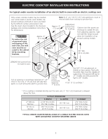
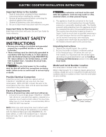
ELECTRIC COOKTOP INSTALLATION INSTRUCTIONS
A
I
B
C
G
H
30” Min. *
(76.2 cm)
E
F
D
All dimensions are in inches (cm).
P/N 318201445 (0812) Rev. G
English – pages 1-6; Español – pages 7-12; Français - pages 13-18; Notes - 19-20
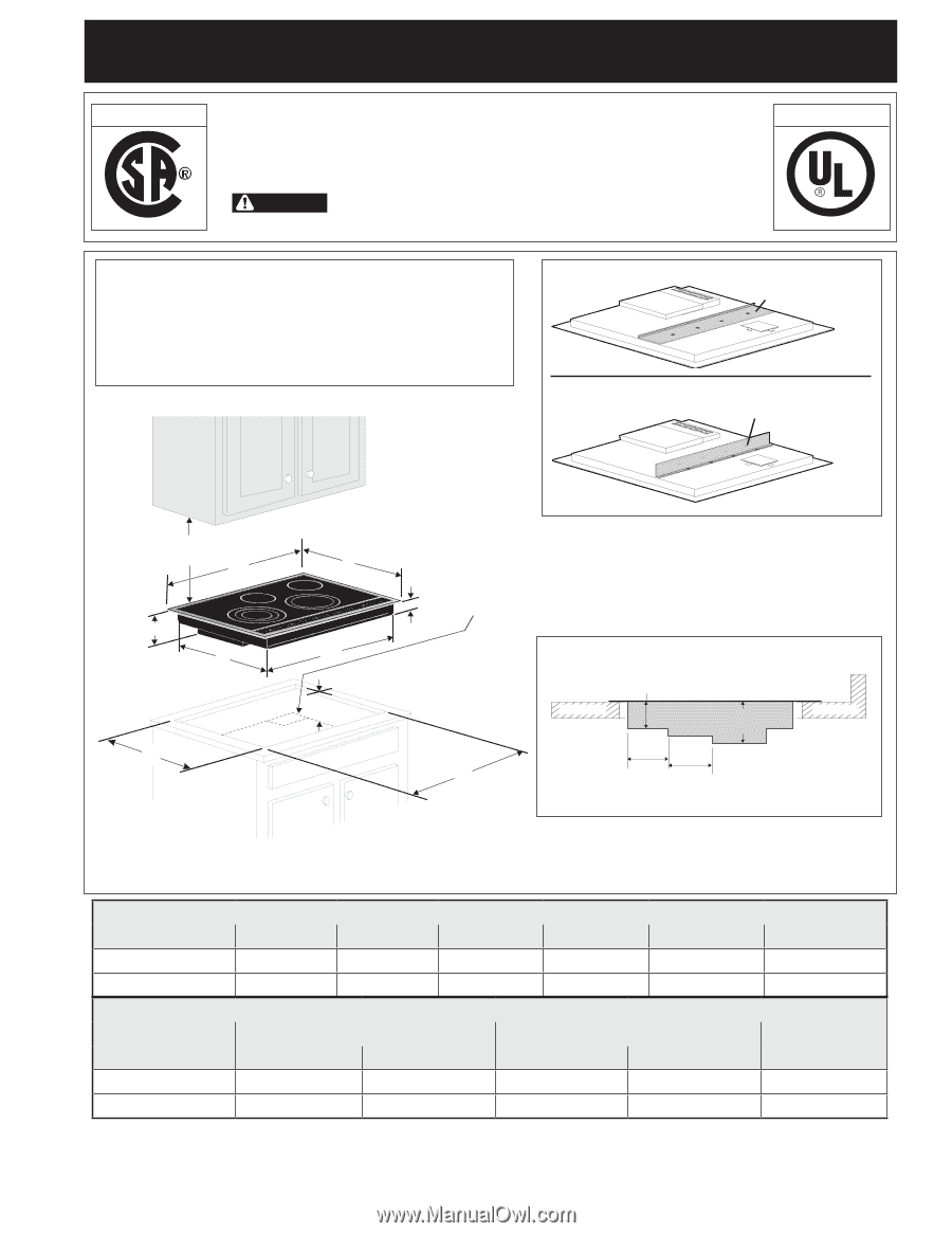
Cooktop Dimensions
IMPORTANT INSTALLATION INFORMATION
• All electric cooktops run off a single phase, three-wire or
four-wire cable, 240/208 volt, 60 hertz, AC only electrical
supply with ground.
• Minimum distance between cooktop and overhead cabi
-
netry is 30" (76.2 cm).
Cooktop Cutout
Dimensions
Figure 1
Printed in United States
IMPORTANT
: If a plywood is present in the cabinet under
the cooktop
, install the deflector supplied under the burner box
(see Fig.1-A) as shown in fig. 1-B and make a 4" X 8" (10.2 cm
x 20.3 cm) opening to route armored cable.
Note:
Remove the
deflector if the cooktop is installed over a wall oven.
* 30" (76.2 cm) min. for unprotected cabinet
24" (61 cm) min. for protected surface
Figure 1-A
Figure 1-B
3 1/8
(7,9)
6 ½
(16,5)
4 ½
(11,4)
6 7/8
(17,5)
Front
Rear
Side view
Countertop
Countertop
Deflector shipping
position
Deflector position when a plywood
is present in the cabinet
INSTALLATION AND SERVICE MUST BE PERFORMED
BY A QUALIFIED INSTALLER.
IMPORTANT: SAVE FOR LOCAL ELECTRICAL INSPECTOR'S USE.
READ AND SAVE THESE INSTRUCTIONS FOR FUTURE REFERENCE.
WARNING
FOR YOUR SAFETY:
Do not store or use gasoline or other
flammable vapors and liquids in the vicinity of this or any other appliance.
Canada
United States
PRODUCT DIMENSIONS
MODEL
A.
WIDTH
B.
DEPTH
C.
HEIGHT
D.
HEIGHT
E.
BOX WIDTH
F.
BOX DEPTH
30’’
Ceramic Model
30 ¾ (78.1)
21 ¾ (55.2)
3
1
/
8
(7.9)
6 ½ (16.5)
28 ½ (72.4)
19
1
/
16
(48.9)
36’’ Ceramic Model
36 ¾ (93.3)
21 ¾ (55.2)
3
1
/
8
(7.9)
6 ½ (16.5)
34
5
/
8
(87.9)
19
1
/
16
(48.9)
CUT OUT DIMENSIONS
G.
WIDTH
H.
DEPTH
I.
HEIGHT BELOW
MODEL
MINIMUM
MAXIMUM
MINIMUM
MAXIMUM
COOKTOP
30’’
Ceramic Model
29 ¾ (75.6)
30 (76.2)
20 3/8 (51.8)
20 ½ (52.1)
8 ½ (21.6)
36’’ Ceramic Model
36 (91.4)
36 ¼ (92.1)
20 3/8 (51.8)
20 ½ (52.1)
8 ½ (21.6)