Epson ActionNote 890 Product Information Guide
Epson ActionNote 890 Manual
 |
View all Epson ActionNote 890 manuals
Add to My Manuals
Save this manual to your list of manuals |
Epson ActionNote 890 manual content summary:
- Epson ActionNote 890 | Product Information Guide - Page 1
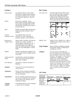
EPSON ActionNote 890 Series Front View l These parts function only with the optional audio card the system board) 128KB Flash ROM device containing the system and video BIOS and Setup program code 512KB DRAM supports resolutions up to 640 X 480 in 256 colors on the color LCD and up to 1024 X 768 in - Epson ActionNote 890 | Product Information Guide - Page 2
PC cards, drivers and utilities for video system and touchpad; online version of User's Guide; all installed on the hard disk drive; refer to About Your Software card for details on EPSON's support policy LCD Screen Screen type (all backlit) Resolutions and colors Diagonal measurement, active area - Epson ActionNote 890 | Product Information Guide - Page 3
EPSON ActionNote 890 Series Fax/modem Specifications Characteristic Compatibility speeds Command set Data correction Data Caution Use only the adapters and replacement batteries designed for use with the ActionNote 890 series (lightweight AC adapter A882051, international AC adapter A882101, auto - Epson ActionNote 890 | Product Information Guide - Page 4
EPSON ActionNote 890 Series Optional Equipment I 4MB, 8MB, or 16MB memory expansion module I User-removable 540MB, 810MB, or 1.2GB hard disk drive I 14.4Kbps baud internal data - Epson ActionNote 890 | Product Information Guide - Page 5
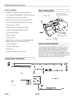
System board components EPSON ActionNote 890 Series Serial port connector (J2) VGA connector for an external monitor (J3) Power converter board connector (22-pin male) Connector Pin Assignments Power converter - Epson ActionNote 890 | Product Information Guide - Page 6
EPSON ActionNote 890 Series External keyboard/mouse connector (J7) Pin Signal Pin Signal 1 AUX-DATA 3 2 NC 4 GND +5 V Microphone connector (J88) Pin Signal Pin 1 AGND 3 2 MICIN 4 Signal BMlC - Epson ActionNote 890 | Product Information Guide - Page 7
PCMCIA connector (P1 and P2) EPSON ActionNote 890 Series Audio-Out connector (J24) Pin Signal Pin 1 AGND 3 2 LOUT1 4 Signal SPK SPK Pin Signal 5 LOUT0 LCD connector (J11, 10-pin) Pin Signal 1 GND - Epson ActionNote 890 | Product Information Guide - Page 8
EPSON ActionNote 890 Series Main board connector to power converter (J17) Pin Signal Pin Signal Pin Signal Pin Signal Touchpad connector (J19) Pin Signal Pin Signal 1 TBDIS 5 - Epson ActionNote 890 | Product Information Guide - Page 9
card Diskette Controller LPT1 Clock/Calendar I Video Available Available I Touchpad Reserved for Coprocessor Hard Disk Drive Controller I Available EPSON ActionNote 890 Series System Memory Map 000000H 0A0000H 0C0000H 640KB base memory 128KB reserved for graphics display area Reserved 0E0000H - Epson ActionNote 890 | Product Information Guide - Page 10
EPSON ActionNote Serial Port 1 Installation/Support Tips Using Low Battery Save to HDD and Instant On I The ActionNote 890 series hard disk using the Low Battery Save to HDD or Instant On options, the PCMCIA services are not reinitialized. The computer recognizes SRAM PC cards, but does not recognize - Epson ActionNote 890 | Product Information Guide - Page 11
Product Support Bulletins None Related Documentation 400521800 EPSON ActionNote 890 Series User's Guide 400526800 About Your Software 400527000 Choosing Your Operating System PL-AN890S EPSON ActionNote 890 Series Parts Price List TM-AN800T EPSON ActionNote 890 Series Service Manual EPSON
-
 1
1 -
 2
2 -
 3
3 -
 4
4 -
 5
5 -
 6
6 -
 7
7 -
8
-
9
-
10
-
11
 |
 |
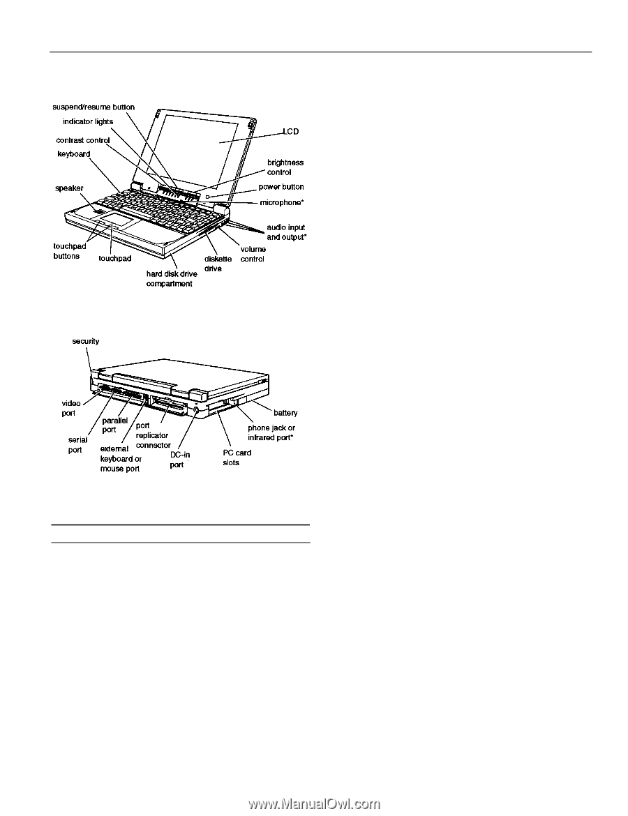
EPSON ActionNote 890 Series
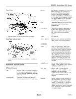
Front View
l
These parts function only with the optional audio card installed.
Rear Panel and Left Side
l
Available only with the optional internal fax/modem or infrared device
installed.
Notebook Specifications
CPU and Memory
CPU
486 DX4/ 100 microprocessor installed in
a PGA socket; includes 8KB of internal
cache in write-back mode and integrated
math coprocessor
System speed
Fast speed and slow speed (8 MHz)
available; speed selection through Setup
Memory
ROM
Video RAM
Cache
Clock/ calendar
Controllers
Video
Diskette drive
Hard disk
PCMCIA
8MB standard, configured with 4 or 8MB
RAM soldered on the system board;
systems with 4MB on system board,
include an additional 4MB memory
module; expandable up to 24MB using a
4, 8, or 16MB memory expansion module
(can install a 20MB module on systems
with 4MB on the system board)
128KB Flash ROM device containing the
system and video BIOS and Setup
program code
512KB DRAM supports resolutions up
to 640
X
480 in 256 colors on the color
LCD and up to 1024
X
768 in 16 colors or
800
X
600 in 256 colors on external
monitor
8KB internal
Real-time clock, calendar, and CMOS
RAM; backed up by internal battery
Chips and Technology® 65535 video
controller; 32-bit local bus interface to
the microprocessor; supports enhanced
video modes on an external monitor;
supports resolutions from 640
x
480 in
256 colors on the color LCD and up to
1024
x
768 in 16 colors on an external
monitor; automatic external monitor
detection; simultaneous display with
LCD screen using
Fn F10
command or
software
Built-in super I/O controller for one
internal 3.5-inch diskette drive; supports
720KB and 1.44MB formats
Built-in super I/O controller has
interface to one 2.5-inch, IDE internal
hard disk drive; automatically
recognizes and configures drives up to
19 mm high that support the IDE
interface
Built-in Vadem® VG-468 controller for
two stacked slots; supports two Type I
or II cards, or one Type III; PCMCIA
version 2.01 and JEIDA 4.1 compatible;
supports low power and suspend
modes; supports hot insertion (including
ExCA standards); register compatible
with Intel® 82365SL,
8/25/95
AN890-1