Epson EU-m30 Developer s Guide
Epson EU-m30 Manual
 |
View all Epson EU-m30 manuals
Add to My Manuals
Save this manual to your list of manuals |
Epson EU-m30 manual content summary:
- Epson EU-m30 | Developer s Guide - Page 1
Developer's Guide *Includes information on OT-BU30. M00139800 EN Rev.A - Epson EU-m30 | Developer s Guide - Page 2
to this product, or (excluding the U.S.) failure to strictly comply with Seiko Epson Corporation's operating and maintenance instructions. Seiko Epson Corporation shall not be liable against any damages or problems arising from the use of any options or any consumable products other than those - Epson EU-m30 | Developer s Guide - Page 3
. In the following cases, immediately turn off the power and contact qualified service personnel. Continued use may lead to fire or electric shock. If Do not touch the inside of the product except where mentioned in the manual. Do not use the product with any voltage and current other than the - Epson EU-m30 | Developer s Guide - Page 4
Caution Labels The caution labels on the product indicate the following precautions. CAUTION: Do not touch the thermal head and the frame on its side because it can be very hot after printing. CAUTION: The sharp edge can cut your fingers. Restriction of Use When this product is used for applications - Epson EU-m30 | Developer s Guide - Page 5
This product (printer unit) is intended to be integrated into a self-service terminal. For details on how to integrate it into a self-service terminal, refer to the following: Appendix M PRINTER INSTALLATION DESIGN GUIDE Appendix N INSTALLING THE POWER SWITCH AND POWER/FEED SWITCH COVER - Epson EU-m30 | Developer s Guide - Page 6
(φ 35 mm) Switch cover For power switch For power/feed switch Small cover open lever, including 1 spare screw Roll paper guides for 58 mm {2.28"} paper: 2 Equipment mounting brackets: 2 Product fixing brackets, including 2 screws + 1 spare (total of 3 screws) Options Bezel - Epson EU-m30 | Developer s Guide - Page 7
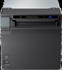
Part Names and Function 5 Front 1 2 3 4 1 Cover open lever 2 Feed button 3 Power switch 4 Roll paper cover 5 Panel LED Operate this lever to open the roll paper cover. Pressing this button once feeds roll paper for one line. Hold down this button to continue feeding roll paper. Turns the - Epson EU-m30 | Developer s Guide - Page 8
OUTLINE (1) Scope of this document This document applies to the EU-m30 and bezel option OT-BU30. (2) Product safety precautions 1) Do not allow a voltage that exceeds the absolute maximum rating to be applied to the power connector. - Epson EU-m30 | Developer s Guide - Page 9
Caution Caution: Hot Surface (See Appendix B.) Caution: Sharp Edges (See Appendix P.) 2 - Epson EU-m30 | Developer s Guide - Page 10
(modular connector) *For specified customer only 22 1.16.4 Allowable interface/power supply cable dimensions 24 2 Structure...25 2.1 EU-m30, Standard model ...25 2.2 For specified customer ...26 3 Function ...27 3.1 Control Commands...27 3.2 Character Code Tables ...27 3.3 Switches - Epson EU-m30 | Developer s Guide - Page 11
Automatic Logo Printing Function ...55 Appendix I SETTING PAPER WIDTH...56 I.1 Notes ...56 I.2 Method for Installing 58 mm {2.28"} Roll Paper Guides 56 Appendix J NOTES ON PRINTING AND BACKFEED 58 Appendix K THAI CHARACTER PRINTING ...59 K.1 Character Size for Printing Thai Characters ...59 - Epson EU-m30 | Developer s Guide - Page 12
SUPPLY OTHER THAN THE PS-180 62 Appendix M PRINTER INSTALLATION DESIGN GUIDE 63 M.1 Notes on Printer Installation...63 M.2 Bezel Option Not Equipped ...75 S.2.3 OPOS (OCX Driver)...75 S.2.4 OPOS for .NET...75 S.2.5 Epson ePOS SDK for Android ...76 S.3 Controlling the Optional External Buzzer (Model - Epson EU-m30 | Developer s Guide - Page 13
printing and limitations Multi-tone graphics printing is possible (up to 16 tones when using our specified paper). Multi-tone printing is not supported in Page mode. Voids (white spaces) may appear depending on the paper type (uneven application of chromogenic coating). It may not be - Epson EU-m30 | Developer s Guide - Page 14
1.4 (1) (2) Paper Sensor Function Detects whether paper is present in the paper path. Method Microswitch 1.5 (1) (2) Roll Paper Supply Device Use roll paper that is not deformed, and ensure there is no slack when setting. Function Supplies paper with a width of 80 mm {3.15"} or 58 mm {2.28"} - Epson EU-m30 | Developer s Guide - Page 15
(3) Print density adjustment depending on the specified original paper In order to ensure optimal print quality and reliability, we recommend using the print density settings in the table below. The initial setting is 100% print density. The print density can be changed using customized values - Epson EU-m30 | Developer s Guide - Page 16
Approx. 9.5 mm {0.37"} Approx. 19.5 mm {0.77"} Paper feed direction Emergency cutting position Autocut position Print position Figure 1.8.1 Printing and Cutting Positions These values are the design center values for the position of the structures, and vary from the top margin values. When - Epson EU-m30 | Developer s Guide - Page 17
1.9 (1) (2) (3) (4) (5) (6) Internal Memory Receive buffer 4 KB or 45 bytes (Select using software settings) Downloaded character area 12 KB (Shared with the downloaded bit image area) Macro area 2 KB NV graphics area 384 KB Downloaded graphics area 208 KB NV user memory area 1 KB 1.10 (1) (2) - Epson EU-m30 | Developer s Guide - Page 18
% (Printing length: 20 mm {0.79"}) 100% (Printing length: 20 mm {0.79"}) Print example ABCDE BCDE 6789 67890 EU-m30: 48 columns 72 mm {2.84"} 72 mm {2.84"} EU-m30 Mean: Approximately 1.5 A Mean: Approximately 3.5 A Mean: Approximately 4.6 A (b) When paper width is set to 58 mm {2.28"} Print - Epson EU-m30 | Developer s Guide - Page 19
must not exceed 20mm {0.79"} when printing with 100% print ratio. (3) AC power consumption (AC100 to 230 V / 50 to 60 Hz) EU-m30 Operating: Approx. 24.2 W Standby: Approx. 0.8 W *Average power under operating conditions. Depends on use conditions and model. 1.11 (1) (2) EMI and Safety - Epson EU-m30 | Developer s Guide - Page 20
printed Note: This is an average failure interval based on failures relating to wear-out and random failures up to the service life. 1.13 (1) Environmental Conditions Guaranteed operating environment (Temperature and humidity) [%RH] 90 5°C {41°F} 90% 80 34°C {93°F} 90% Relative humidity 60 - Epson EU-m30 | Developer s Guide - Page 21
Test result No visible exterior or interior damage, and no abnormal operation. (4) Impact resistance (a) When packed Drop conditions Packing method: Epson standard package Height: 60 cm {23.62"} Directions: 1 corner, 3 edges, and 6 surfaces Test method After dropping under the above - Epson EU-m30 | Developer s Guide - Page 22
direction. Z direction Y direction X direction Figure 1.13.2 Direction of Impact (5) Acoustic noise (a) Operation noise Test conditions: Epson standard Test method: Epson standard Measuring result: Approx. 60 dB (Bystander position) Note: Measured value fluctuates depending on the - Epson EU-m30 | Developer s Guide - Page 23
1.15.2 USB interface (1) USB connector Type USB upstream port connector (USB type-B connector) Pin assignments Pin number Signal name 1 VBUS 4 3 2 D- 3 D+ 4 GND 1 2 Shell Shield (2) USB communication specifications (a) USB functions Overall specifications: Complies with - Epson EU-m30 | Developer s Guide - Page 24
If this USB Device Request is requested, the printer returns the following character string. [00H][XXH] *1 MFG:EPSON; CMD:ESC/POS; MDL:EU-m30; *2 CLS:PRINTER; DES:EPSON[SP]EU-m30; *2 CID:EpsonTM00001021; *2 *1: DeviceID character string size *2: The character string depends on the language model and - Epson EU-m30 | Developer s Guide - Page 25
1.15.3 RS-232 serial interface (1) Connectors Type D-SUB9 (Male) Pin assignments Pin number Function 1 - 2 RXD 3 TXD 4 DTR 5 SG 6 DSR 7 RTS 8 - 9 - Shell Shield (2) Specifications (Complies with RS-232) Data transmission method: Serial Synchronization: Asynchronous - Epson EU-m30 | Developer s Guide - Page 26
(4) Interface connector terminal assignments and signal functions Table 1.15.1 Signal Layout and Functions Pin number Signal name Signal direction Function 2 RXD Input Data reception 3 TXD Output Data transmission 4 DTR Output When DTR/DSR control is selected: This signal indicates - Epson EU-m30 | Developer s Guide - Page 27
(1) If Memory switch 5-2 is OFF: The printer status becomes "buffer full" from when the remaining space in the receive buffer drops to 128 bytes until such time that the remaining space in the receive buffer increases to 256 bytes. (2) If Memory switch 5-2 is ON: The printer status becomes "buffer - Epson EU-m30 | Developer s Guide - Page 28
2) When setting Memory switch 1-3 to ON to enable handshaking with the printer, be sure to check the printer status using the GS a command and the automatic status back function of the data dependent on that command. In this setting, the default value of n for GS a is 2. The printer automatically - Epson EU-m30 | Developer s Guide - Page 29
1.16.3 Drawer kick connector (modular connector) *For specified customer only (1) Function Connect to the drawer or the optional external buzzer. The pulse specified by the ESC p or DLE DC4 command is output to this connector. The host computer can confirm the status of the input signal by - Epson EU-m30 | Developer s Guide - Page 30
(5) Drawer open/close signal Drawer-kick connector F. G 1 2 A 3 Control device P-GND +24V 4 Shielded Drawer-kick solenoid 5 B 6 Drawer open/close switch P-GND Printer side User side (Drawer side) Figure 1.16.2 Drawer Kick Connection Diagram Use a shielded cable for the drawer - Epson EU-m30 | Developer s Guide - Page 31
1.16.4 Allowable interface/power supply cable dimensions 12 1 1 (Type-B Plug) 13 1 3 Note: User must confirm that the connector plug and cable fit in the storage space. 24 - Epson EU-m30 | Developer s Guide - Page 32
2 Structure 2.1 EU-m30, Standard model (1) Exterior 1 2 3 1: Cover open lever (2) Interfaces equipped USB and For power/feed switch Small cover open lever, including 1 spare screw Roll paper guides for 58 mm {2.28"} paper: 2 Equipment mounting brackets: 2 Product fixing brackets - Epson EU-m30 | Developer s Guide - Page 33
2.2 (1) (2) (3) For specified customer Exterior Same as EU-m30 (See 2.1.(1).) Interfaces equipped USB and serial (RS-232, D-Sub 9 pin) power/feed switch Small cover open lever, including 1 spare screw Roll paper guides for 58 mm {2.28"} paper: 2 Equipment mounting brackets: 2 Product - Epson EU-m30 | Developer s Guide - Page 34
.com/pos/reference/). 3.2 Character Code Tables See "Character Code Tables for TM Printers"(www.epson-biz.com/pos/reference/). 3.3 Switches 3.3.1 Power switch (1) Type Locking push switch (2) Function (a) Turn the power on or off. Notes: Operate the power switch with the - Epson EU-m30 | Developer s Guide - Page 35
on the paper sensor status. *2 See Appendix D.2. *3 Can select with the EU-m30 Utility. [ ]: Set when shipped. *4 Flashing starts when print job is completed. Can select the flashing duration with the EU-m30 Utility. When the flashing duration ends, the light turns Off. If, - Epson EU-m30 | Developer s Guide - Page 36
with GS ( E . For details, see "ESC/POS Command Reference" (www.epson-biz.com/pos/reference/). (b) Software setting mode (except some functions) For details, see 3.8.3 Software setting mode. (c) EU-m30 Utility Table 3.5.1 Memory Switch 1 (Msw1) Msw Function Setting value 48 (OFF - Epson EU-m30 | Developer s Guide - Page 37
and the system configuration is set so that the USB driver can support the USB power-saving function. *2: When a customized value (specification (www.epson-biz.com/pos/reference/). (b) Software setting mode (except some functions) For details, see 3.8.3 Software setting mode. (c) EU-m30 Utility - Epson EU-m30 | Developer s Guide - Page 38
Pattern B Buzzer function: Buzzer frequency (Pulse 2) *1 Does not sound/sounds 1 time Sounds 1 time Command-compatible mode EU-m30/TM-m30/TM-m30II EU-m30 Selection of batch print enabled/disabled and print direction Disabled/enabled (forward)/enabled Disabled (reverse) *1: The functions are - Epson EU-m30 | Developer s Guide - Page 39
GS ( E . For details, see "ESC/POS Command Reference" (www.epson-biz.com/pos/reference/). (b) Software setting mode (except some functions) For details, see 3.8.3 Software setting mode. (c) EU-m30 Utility (except some functions) Function Class Table 3.5.5 USB Interface Communication - Epson EU-m30 | Developer s Guide - Page 40
For details, see "ESC/POS Command Reference" (www.epson-biz.com/pos/reference/). (b) EU-m30 Utility (except some functions) Function Table 3.5.7 Receipt Enhancement setting The following settings can be changed using the EU-m30 Utility. Function Light on in normal status Printing completed - Epson EU-m30 | Developer s Guide - Page 41
3.6 Self-test 3.6.1 Self-test function Executes printer status printing and rolling pattern printing. (a) Printer status printing Product name Firmware version Product serial number Interface information Built-in character fonts Maintenance information (Head running length, number of - Epson EU-m30 | Developer s Guide - Page 42
of the printer status starts. Step 2: After the printer status is printed, press the Feed button until printing of the instructions for operation method starts. Step 3: After the instructions for operation are printed, press the Feed button once. Step 4: Then, press and hold the Feed button until - Epson EU-m30 | Developer s Guide - Page 43
of the printer status starts. Step 2: After the printer status is printed, press the Feed button until printing of the instructions for operation method starts. Step 3: After the instructions for operation are printed, press the Feed button twice. Step 4: Then, press and hold the Feed button until - Epson EU-m30 | Developer s Guide - Page 44
button four times. Step 4: Then, press and hold the Feed button until printing of the initial setting restoration mode starts. Step 5: After the instructions are printed, press the Feed button once. Step 6: Press and hold the Feed button until the restoration complete message is printed. Ending the - Epson EU-m30 | Developer s Guide - Page 45
3.9.2 (1) 3.9.3 (1) (2) (3) (4) (5) Recoverable errors Autocutter error Error contents: LED display pattern: Recovery method: Detected an error in the autocutter operation. See 3.4.2. Execute DLE ENQ 1 and DLE ENQ 2. Remove any paper jams or foreign objects and close the roll paper cover. - Epson EU-m30 | Developer s Guide - Page 46
3.11 (1) (2) Print Buffer-full Printing When in Standard mode When subsequent data is received after the printer processes one line of data in the print buffer, the printer automatically prints the processed line and feeds the paper by one line. When in Page mode When subsequent data is received - Epson EU-m30 | Developer s Guide - Page 47
ESC &, ESC ?, GS ( D, GS ( L , GS *, GS :, GS D , GS ^, FS 2 (*3) If you are using ePOS-Print SDK or Epson ePOS SDK, the maintaining or initializing of print settings when closing the connection does not affect the operations of the application. (*4) For the method - Epson EU-m30 | Developer s Guide - Page 48
Note: Do not to turn off the printer's power while the firmware update tool is performing the update. (2) Recovery method for when updating the firmware fails If updating the firmware fails, and the Power and Error LEDs flash at the same time when the power is turned on, try updating the firmware - Epson EU-m30 | Developer s Guide - Page 49
127 mm {5"} Depth: Approximately 155.9 mm {6.14"} Height: Approximately 127 mm {5"} Approximately 129 mm {5.1"} (including protrusions) Mass: Approximately 1.3 kg {2.87 lb} (roll paper excluded) 4.2 Color EPSON standard color: ENB9, EBCK 42 - Epson EU-m30 | Developer s Guide - Page 50
4.3 External Dimensions 4.3.1 Bezel Option Not Equipped [Units: mm] Figure 4.3.1 External Dimensions (Bezel Option Not Equipped) 43 - Epson EU-m30 | Developer s Guide - Page 51
4.3.2 Bezel option equipped [Units: mm] Figure 4.3.2 External Dimensions (Bezel Option Equipped) 44 - Epson EU-m30 | Developer s Guide - Page 52
4.4 Dimensions for Installing to Customer Device See Appendix M. 45 - Epson EU-m30 | Developer s Guide - Page 53
the autocutter and causes the autocutter to lock up, the printer enters an error state and begins the recovery operation automatically. If the problem is not serious, the autocutter recovers and returns to its normal position. If the error cannot be resolved even after recovery operations, open - Epson EU-m30 | Developer s Guide - Page 54
Appendix B PRINT HEAD AND PLATEN ROLLER CLEANING B.1 Thermal Head Paper dust or other foreign objects on the thermal elements may lower the print quality. In this case, clean the print head as follows: Step 1: Open the roll paper cover. Step 2: Clean the thermal elements of the print head using a - Epson EU-m30 | Developer s Guide - Page 55
Appendix C NOTES ON USING THE DRAWER KICK CONNECTOR *For specified customer only C.1 Conditions for Using the Drawer Kick Connector Drawer specifications differ significantly depending on the manufacturer and the model. Make sure that the specifications of the drawer used meet the following - Epson EU-m30 | Developer s Guide - Page 56
Figure C.1.1 shows the drive signal waveform generated when the drawer is driven according to the above conditions. ON OFF t1 × 2 ms t2 ≥ (t1 × 4) × 2 ms Figure C.1.1 Drawer Drive Signal Waveform The ON time depends on the specifications of the drawer used. Be sure to check the drawer - Epson EU-m30 | Developer s Guide - Page 57
The drive signal waveform generated when the drawer is driven according to the above conditions is shown in Figure C.1.2. ON OFF 200 ms 500 ms α = 300 ms Figure C.1.2 Drawer Drive Signal Waveform 50 - Epson EU-m30 | Developer s Guide - Page 58
Appendix D NOTES ON UPDATING THE MAINTENANCE COUNTER AND TURNING THE PRINTER'S POWER OFF D.1 About Updating the Maintenance Counter This printer has a maintenance counter with functions as described in the command description for GS g 0 and GS g 2. The values of the maintenance counter are - Epson EU-m30 | Developer s Guide - Page 59
Appendix E NOTES ON PRINTING BAR CODES AND 2-DIMENSIONAL SYMBOLS User must set the quiet zone, depending on the bar code standards. When printing PDF417 (2-dimensional symbols), it is recommended to set the height of one step of the symbol to three to five times the width of one module. The - Epson EU-m30 | Developer s Guide - Page 60
Appendix F NOTES ON SCANNING THE PRINT RESULT ON THE RECEIPT To determine whether the ability of the reader (scanner) can be satisfied by using bar codes, 2-dimensional symbols, or characters printed on receipt (roll paper), take the following points into consideration. 1) Print density The print - Epson EU-m30 | Developer s Guide - Page 61
Appendix G NOTES ON USING THE ASB STATUS Any accumulated ASB status signals left for transmission from the last to the newest ASB status transmission shall be transmitted together at a time as one ASB status showing the presence of change, followed by the latest ASB status. Example: In the normal ( - Epson EU-m30 | Developer s Guide - Page 62
Appendix H NOTES ON ARP (AUTOMATIC REDUCTION OF PAPER) AND AUTOMATIC LOGO PRINTING FUNCTION H.1 ARP: Reduction of Excessive Top Margin, Reduction of Excessive Bottom Margin, Reduction of Line Spacing, and Reduction of Line Spacing Where Extra Line Feeds Are Included Paper reduction is not - Epson EU-m30 | Developer s Guide - Page 63
dulled. Therefore, printing and auto-cutting cannot be done for the expanded section of the paper width.) I.2 Method for Installing 58 mm {2.28"} Roll Paper Guides Step 1: Check that the printer's power is off, then open the roll paper cover. Step 2: Align the three protrusions of the 58 mm {2.28 - Epson EU-m30 | Developer s Guide - Page 64
Step 3: Align the three protrusions of the other 58 mm {2.28"} width roll paper guide (not marked as L SIDE) with the slits on the opposite side of the printer, and insert them. Figure I.3 Step 4: Set the roll paper. Step 5: Close the roll paper cover, then turn the printer power on. 57 - Epson EU-m30 | Developer s Guide - Page 65
Appendix J NOTES ON PRINTING AND BACKFEED 1) If top margin specification via backfeed (3.5.2 (2)) is enabled, the backfeed operation is performed before starting printing directly after the autocut. If top eject, this backfeed operation is performed after the paper in the eject port is removed. 2) - Epson EU-m30 | Developer s Guide - Page 66
Appendix K THAI CHARACTER PRINTING To print using Thai characters, you can use the Thai character 1-pass print mode or Thai character 3-pass print mode. Select the Thai character print mode in the software settings. (See Section 3.5.2 for how to change the setting.) K.1 Character Size for - Epson EU-m30 | Developer s Guide - Page 67
1line K.2 Character Structure for Thai Character 1-pass Print Mode 1line 35dot 6dot 17dot 12dot 46dot 24dot 15dot 12dot 57 1 2 3 6 8 10 9dot 57 1 2 3 6 8 10 7dot 4 9 Font A 4 9 Font B Figure K.2.1 Thai Character 1-pass Print Mode Fonts A and B The numbers in the figure indicate the - Epson EU-m30 | Developer s Guide - Page 68
1line 1line 1line K.3 Character Structure for Thai Character 3-pass Print Mode 24dot 12dot 1 2 3 4 5 6 7 8 9 10 11 12 1line 17dot 9dot 123456 7 8 9 10 11 12 51dot 17dot 1line 72dot 24dot 17dot 13 14 15 16 17 18 13 14 15 16 17 18 1line 24dot Font A Font B Figure K.3.1 Thai - Epson EU-m30 | Developer s Guide - Page 69
Appendix L USING A POWER SUPPLY OTHER THAN THE PS-180 If the power supply has low performance or the print duty is high, the power supply might become cut off. In such a cause, you may be able to avoid power supply cut-offs through the combination of the power supply capacity setting, print speed - Epson EU-m30 | Developer s Guide - Page 70
Appendix M PRINTER INSTALLATION DESIGN GUIDE M.1 Notes on Printer Installation Take into consideration paper equipment mounting brackets and one product fixing bracket for fastening the brackets to the EU-m30. Figure M.1 Equipment Mounting Brackets Figure M.2 Product Fixing Bracket The two - Epson EU-m30 | Developer s Guide - Page 71
Fasten the two equipment mounting brackets, insert the printer from the interface side, and align the position such that the printer and bracket engagement points. Figure M.4 Positioning the Printer Insert the protrusions of the product fixing bracket into the equipment mounting bracket holes, - Epson EU-m30 | Developer s Guide - Page 72
M.2 Bezel Option Not Equipped If impact may possibly be applied, provide support for the printer on the equipment side. Z direction: Printer support X direction: Printer support X direction: Printer support 65 - Epson EU-m30 | Developer s Guide - Page 73
Y direction: Printer support X direction: Printer support 66 - Epson EU-m30 | Developer s Guide - Page 74
M.3 Bezel Option Equipped If impact may possibly be applied, provide support for the printer on the equipment side. Z direction: Printer support X direction: Printer support 67 - Epson EU-m30 | Developer s Guide - Page 75
Y direction: Printer support X direction: Printer support 68 - Epson EU-m30 | Developer s Guide - Page 76
Appendix N INSTALLING THE POWER SWITCH AND POWER/FEED SWITCH COVER N.1 Installing the Switch Cover Step 1: Clean the area around the switch. Step 2: Peel off the switch cover's double-sided adhesive tape, and affix such that the switch cover's rear protrusions enter the power switch's recesses. - Epson EU-m30 | Developer s Guide - Page 77
Appendix O REPLACEMENT FOR SMALL COVER OPEN LEVER To prevent malfunction, the cover open lever can be replaced with the included small cover open lever. O.1 Replacement for Small Cover Open Lever Step 1: Check that the printer's power is off, then open the roll paper cover. Step 2: Press down on the - Epson EU-m30 | Developer s Guide - Page 78
Appendix P BEZEL OPTION (OT-BU30) P.1 Notes on Using the Bezel Option (OT-BU30) 1) A bezel option (OT-BU30) can be used with this printer. 2) If using the bezel option (OT-BU30), the printer's paper can only be ejected in the front direction. 3) Confirm that there is enough space even when the - Epson EU-m30 | Developer s Guide - Page 79
Figure P.3 72 - Epson EU-m30 | Developer s Guide - Page 80
Appendix Q RECOMMENDED POWER SUPPLY A power supply with a rating of 24 V/2.1 A or higher (50.6 W or higher) is recommended. If a power supply less than 24 V/2.1 A (less than 50.6 W) is used, printing may temporarily stop and uneven print density may occur. Incidentally, by using customized - Epson EU-m30 | Developer s Guide - Page 81
be somewhat light due to the head being cold. R.6 When using at high temperature When printing at high temperature, print bleeding or other print quality problems may occur. 74 - Epson EU-m30 | Developer s Guide - Page 82
for printer application development. S.1 Controlling the Printer The printer supports the following command systems: ESC/POS S.1.1 Users can the DirectIO function. For details, see the "EPSON OPOS ADK MANUAL APPLICATION DEVELOPMENT GUIDE Cash Drawer" and the "UnifiedPOS Specification". You - Epson EU-m30 | Developer s Guide - Page 83
.NET Register a POS printer using the SetupPOS Utility and control using the DirectIO function. For details, see the "EPSON OPOS ADK for .NET MANUAL Application Development Guide POSPrinter". Epson ePOS SDK for Android The command for the buzzer function is provided in each SDK library. For details - Epson EU-m30 | Developer s Guide - Page 84
applications of smart devices. This includes libraries, manuals, and sample programs. EPSON OPOS ADK This OCX driver can control POS attached to this driver. EPSON TM Virtual Port Driver This is a serial/parallel-USB/LAN conversion driver to make an Epson TM/BA/EU printer connected via USB or - Epson EU-m30 | Developer s Guide - Page 85
S.4.3 Utilities Software Epson TM Utility EU-m30 Utility Deployment Tool Monitoring Tool EU-m30 Firmware Updater Description can obtain software and manuals from one of the following URLs. For customers in North America, go to the following web site: → www.epson.com/support/ For customers in
-
 1
1 -
 2
2 -
 3
3 -
 4
4 -
 5
5 -
 6
6 -
 7
7 -
8
-
9
-
10
-
11
-
12
-
13
-
14
-
15
-
16
-
17
-
18
-
19
-
20
-
21
-
22
-
23
-
24
-
25
-
26
-
27
-
28
-
29
-
30
-
31
-
32
-
33
-
34
-
35
-
36
-
37
-
38
-
39
-
40
-
41
-
42
-
43
-
44
-
45
-
46
-
47
-
48
-
49
-
50
-
51
-
52
-
53
-
54
-
55
-
56
-
57
-
58
-
59
-
60
-
61
-
62
-
63
-
64
-
65
-
66
-
67
-
68
-
69
-
70
-
71
-
72
-
73
-
74
-
75
-
76
-
77
-
78
-
79
-
80
-
81
-
82
-
83
-
84
-
85
 |
 |

Developer’s Guide
*Includes information on OT-BU30.
M00139800 EN
Rev.A