Epson FX 1170 Service Manual
Epson FX 1170 - B/W Dot-matrix Printer Manual
 |
View all Epson FX 1170 manuals
Add to My Manuals
Save this manual to your list of manuals |
Epson FX 1170 manual content summary:
- Epson FX 1170 | Service Manual - Page 1
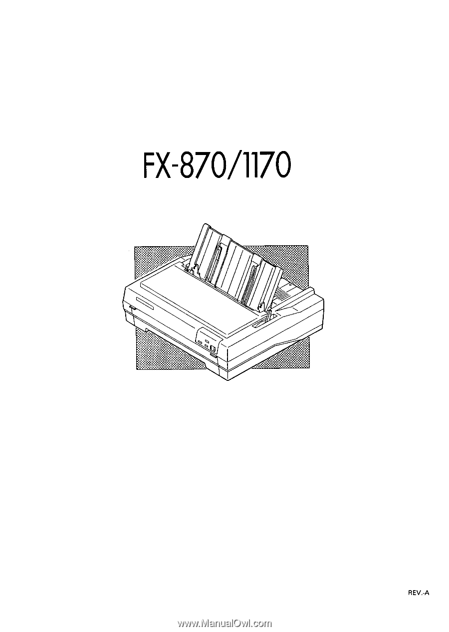
EPSON EPSON TERMINAL PRINTER FX-870/1170 SERVICE MANUAL 4001461 REV.-A - Epson FX 1170 | Service Manual - Page 2
.-. NOTICE " All rights reserved. Reproduction of any part of this manual in any from whatsoever without SEIKO EPSON's express written permission is forbidden. " The contents of this manual are subject to change without notice. " All efforts have been made to ensure the accuracy of the contents of - Epson FX 1170 | Service Manual - Page 3
WHEN PERFORMING TESTING AS DICTATED WITHIN THIS MANUAL, DO NOT CONNECT THE UNIT TO A POWER SOURCE UNTIL INSTRUCTED TO DO SO. WHEN THE POWER SUPPLY AS THE RATED VOLTAGE, LISTED ON THE SERIAL NUMBER/RATING PLATE. IF THE EPSON PRODUCT HAS A PRIMARY-AC RATING DIFFERENT FROM THE AVAILABLE POWER SOURCE, DO - Epson FX 1170 | Service Manual - Page 4
2 - Describes the theory of printer operation. Chapter 3 - Includes a step-by-step guide for product disassembly and assembly. Chapter 4 - Includes a step-by-step guide for adjustment. Chapter 5 - Provides Epson-approved techniques for troubleshooting. Chapter 6 - Describes preventive maintenance - Epson FX 1170 | Service Manual - Page 5
REVISION SHEET REVISON A DATE ISSUED June 15, 1992 CHANGE DOCUMENT 1st issue . ,. :;: \ f . . (*" '?: .7,, -v- - Epson FX 1170 | Service Manual - Page 6
TABLE OF CONTENTS CHAPTER 1. CHAPTER 2. CHAPTER 3. CHAPTER 4. CHAPTER 5. CHAPTER 6, APPENDIX GENERAL DESCRIPTION OPERATING PRINCIPLES DISASSEMBLY AND ASSEMBLY ADJUSTMENTS TROUBLESHOOTING MAINTENANCE REV.-A - vi - - Epson FX 1170 | Service Manual - Page 7
1.2.1.3 Paper Specifications 1. .-6 1.2.1.4 Printable Area 1. -. 9 1.2.1.5 Ribbon Cattridge 1. .-11 1.2.1.6 Electrical Specifications 1. . 24 1.5.10 Sheet Loading and Sheet Ejection 1. -25 1.5.11 Adjust Lever Operation 1. .-25 1.5.12 Printer Initialization 1. .-26 1.5.13 Buzzer o 1-27 l-i - Epson FX 1170 | Service Manual - Page 8
3O 1.6.3 BOARD ASSEMBLY, C076PSBFSE (Power SuPPIY circuit Board) ......1 -30 1.6.4 Printer Mechanism 1. .-.31 1.6.5 Housing Assembly 1. . -. 32 LIST OF FIGURES Figure 1-1. External View of FX-870/1170 1. .-2 Figure 1-2. Pin Configuration 1. .-.4 Figure 1-3. Printable Area for Cut Sheets - Epson FX 1170 | Service Manual - Page 9
(carbonless Dwli-tim paPer) ...".s 1-7 Table 1-4. Specifications for Continuous Paper 1. -7 Table 1-5. Specifications for Envelopes 1. .-7 Table 1-6. Specifications for Labels 1. .-8 Table 1-7. Specifications for Roll Paper 1. .-8 Table 1-8. Electrical Specifications for 120V Model 1. -12 Table - Epson FX 1170 | Service Manual - Page 10
1.1 Scope These specifications apply to the EPSON FX-87WI 170 dot matrix Printer. 1.1.1 Features q Upward compatibility with the FX-850(+)/1050(+), FX-800/1000, FX-86e/286e q 380 cps (high-speed draft for both 80 and 136-column models) q 285 cps (draft pica), 342 CPS (draft elite) q Advanced paper - Epson FX 1170 | Service Manual - Page 11
REV.-A 80-column model . 4% ~.- r~.... . " 136-column model Figure 1-1. External View of the FX-870/1170 . ,. 1-2 - Epson FX 1170 | Service Manual - Page 12
) Front sheet guide (136-column) Serial l/F card Serial l/F card 32KB intelligent serial l/F card 32KB intelligent serial l/F card 32KB intelligent parallel l/F card 32KB intelligent parallel l/F card 32KB IEEE-488 l/F card Fabric ribbon cartridge ( 80-column) Fabric ribbon cartridge (136-column - Epson FX 1170 | Service Manual - Page 13
1.2 Specifications 1.2.1 Hardware Specifications 1.2.1.1 Printing Method Printing method: Impact dot matrix Pin configuration: 9 wires (diameter 0.29 mm) wire 2+--- - - $ 0.35mm (lf12") 3 ' ------9 9& Figure 1-2. Pin Configuration Dot matrix: 9 x 7 matrix (high-speed draft) 9 x 9 matrix (draft - Epson FX 1170 | Service Manual - Page 14
ips) Thick ms (ips) Fanfold paper 77 85 55 (3.0) 66 (2.5) Cut sheet (manual) 69 77 45 (3.7) 55 (3.0) Cut sheet (CSF) 71 77 48 (3.5) 55 end has been detected. q Use the paper-tension unit. q Insert the multi-part cut sheet forms only from the front. 2) Push tractor feed q Set the - Epson FX 1170 | Service Manual - Page 15
adjust the horizontal position of the pull tractor and push tractor. q Multi-part paper must be carbonless. q Do not perform reverse feeds greater than 1/6". C (59-68 deg. F) Humidity: 30-60 ?!. RH Table 1-2. Specifications for Cut Sheets (Plain Paper) ~....- q "- Width top insertion 148- - Epson FX 1170 | Service Manual - Page 16
(40-58 g/m2) - each 4 sheets (1 original + 3 copies) maximum Table 1-4. Specifications for Continuous Paper Width Thickness Weight Quality Copies 101-254 mm (4-10") 80-column 101-406 No. 6 envelope at the sheet guide setting mark. 4) Do not feed envelopes with the cut sheet feeder. REV.-A 1-7 - Epson FX 1170 | Service Manual - Page 17
. 4) Do not perform reverse feed at any time. (including by hand). z 5) Remove labels from the paper path when not in use. i .3., Table 1-7. Specifications for Roll Paper Size Thickness Weight Quality 216 +/- 3 mm (8.5 +/- 0.12") 0.07-0.09 mm (0.0028-0.0035") 14-22 lb (45-70 Kg) (52.3-82 - Epson FX 1170 | Service Manual - Page 18
1.2.1.4 Printable Area 1) Cut sheets top insertion front insertion 148-257 mm (5.8-10.1"): 80 columns 148-420 mm (5.8-16.5") : 136 columns 182-257 mm (7.2-10.1"): 80 columns 182-364 mm (7.2-14.3"): 136 columns < q 1 *1 1. T" I_WXYZ REV.-A I ABCD -1- WXYZ Figure - Epson FX 1170 | Service Manual - Page 19
REV.-A 2) Continuous paper < *1 < A. ABCD t Printable Area > *1, L\ i WXYZ I_ 4--ABCD WXYZ 4 Figure 1-4. Printable Area for Continuous Paper *1 13 mm (0.51") or more when the paper width is 101 mm to 241 mm (4" to 9.5"). 25 mm (1.0") or more ~~. when the paper width is 254 mm (10"). ( 80 - Epson FX 1170 | Service Manual - Page 20
more Note: Paper feed accuracy cannot be assured within 24 mm (0.94") from the bottom edge of the paper. (top insertion only) 1.2.1.5 Ribbon Cartridge Ribbon Cartridge type (same as FX series) # 8750 - 80-column model # 8755(M) - 136-column model # 8758- Subcartridge Color Black Life of - Epson FX 1170 | Service Manual - Page 21
) Approx. 45 W (136 columns) (Self test in draft mode, 10 cpi) 1.0 kVAC, 1 second (Between AC line and chassis) Table 1-9. Electrical Specifications for220/240V Model Rated voltage Input voltage range Rated frequency range Input frequency range Rated current Power consumption Dielectric strength - Epson FX 1170 | Service Manual - Page 22
Between Failures) Printhead Life 100 million characters (14 dots/character) REV.-A 1.2.1.9 Safety Approvals Safety standards UL1950 ) (EUR model) 1.2.2 Firmware Specifications 1.2.2.1 Print Control Printing direction Text specified by software.) Bit image mode Unidirectional printing - Epson FX 1170 | Service Manual - Page 23
REV.-A Table 1-11. Character Size and Pitch I Type of letters I Width I Height I Character pitch [mm] [mm] [mm] Pica 2.1 3.1 2.54 (10 cpi) Condensed 1.05 3.1 1.48 (17 cpi) Elite 1.7 3.1 2.11 (12 cpi) I Condensed elite \ 0.85 I 3.1 I 1.27 (20 cpi) . f Table 1-12. Printable - Epson FX 1170 | Service Manual - Page 24
, 1.3 Interface This printer has a built-in, 8-bit centronics parallel interface. 1.3.1 Parallel Interface Data transmission mode Synchronization Handshaking Logic level Connector plug 8-bit parallel Controlled by external STROBE pulse. Controlled by ACKNLG and BUSY signals. ITL- compatible 57- - Epson FX 1170 | Service Manual - Page 25
automatically fed one line upon receipt of a CR code. (The signal level can be set LOW by default.) Not used. Logic GND level. Printer chassis GND. In the printer, the chassis GND and the logic GND are shortcircuited. Not used. TWISTED-PAIR RETURN signal GND level. When the level of this signal - Epson FX 1170 | Service Manual - Page 26
, 1.3.2 Optional Interface The following interface cards can be used for this printer. Table 1-15. Optional Interface Catalog # Type C82305* (inch screw) Serial I/F card C82306* (inch screw) Serial l/F card C82307* (inch screw) 32KB intelligent serial l/F card C82308* (inch - Epson FX 1170 | Service Manual - Page 27
Selects printing or pause alternately when there is some data to print in the input buffer. Advances continuous paper to tear-off position when the printer has printed all received data and is ready to receive more print data. [PAPER FEEDI Advances the paper line by line using the current line - Epson FX 1170 | Service Manual - Page 28
by manual insertion). You can end micro feed (or micro adjust) mode by pressing the FONT button again. The printer exits this mode automatically in several seconds if no operation is performed. Pressing FONT+ PAUSE or FONT+ PAPER FEED switches bins when a double-bin CSF is installed - Epson FX 1170 | Service Manual - Page 29
REV.-A 1.5 Functions c.,!,.. , 1.5.1 Default Settings Users can set certain default parameters, which will be used at printer initialization. To change the parameters shown in Table 1-16, Group 1 Features, follow the steps below. 1. Turn on the printer while pressing the FONT button. Then, the - Epson FX 1170 | Service Manual - Page 30
I ault$ I - Iu. -g uup m rcacul ca FONT LED OFF COND. LED ON Feature Emulation OFF BLINKS Character pitch ON OFF Page length ON ON ON BLINKS Skip over perforation BLINKS OFF Zero face BLINKS ON Auto tear-off BLINKS BLINKS Auto LF with CR Setting ESC/P IBM Proprinter Pica Elite 11 inch - Epson FX 1170 | Service Manual - Page 31
REV.-A Table 1 7. Group 2 Features (ESC/P Mode) FONT COND. I LED I LED READY LED CG table ON Italic U. S. A.(std. setting) BLINKS France I OFF I ON OFF ON OFF ON I Germany U.K. OFF ON BLINKS I Denmark OFF BLINKS OFF Sweden OFF BLINKS ON Italy OFF BLINKS BLINKS Spain - Epson FX 1170 | Service Manual - Page 32
its power on parameters. To change the settings shown in Table 119, Group 3 Features (Power on settings), follow the steps below. 1. Turn on the printer while pressing the PAUSE, PAPER FEED, and FONT buttons. 2. Press the button indicated in Table 1-19 for a few seconds to change parameters. Table - Epson FX 1170 | Service Manual - Page 33
the pause condition automatically after feeding or printing several lines. When a paper-out is detected, load new paper properly and set the printer ready to print by pressing the PAUSE button. 1.5.7 Auto Tear-off a., {>,. ..-"" When the release lever is set to one of the tractor positions - Epson FX 1170 | Service Manual - Page 34
feeder Move the release Ievertothe FRICTION position and load a sheet using the paper guide (top or optional front). A few seconds later, the sheet is automatically loaded to the top-of-form position, and the printer becomes ready to print. (b) Automatic cut sheet loading and ejection with the cut - Epson FX 1170 | Service Manual - Page 35
is initialized, it performs the following functions: q The printhead returns to the leftmost position (carriage home). q The READY LED lights. q The printer clears the print buffer and input data buffer. q The line spacing is set to 1/6 inch. q The page length and skip over perforation settings - Epson FX 1170 | Service Manual - Page 36
, to indicate different meanings. In the following table, each "*" stands for one beep. Table 1-21. Buzzer Functions Status BEL code Carriage trouble Voltage error Fatal error Incorrect memory Paper error Illegal paper release/u nrelease Recognition of operation Micro feed Sound and Description - Epson FX 1170 | Service Manual - Page 37
are: (1) BOARD ASSEMBLY, C094 MAIN (2) BOARD ASSEMBLY, C094 PNL (3) BOARD ASSEMBLY, C076 PSB/PSE (4) Printer Mechanism (5) Housing Assembly The following figure shows the main components of the FX-870/l 170. Platen Ga f-:: PSB/PSE -.. " y, C094 M AIN Pril 7 Figure 1-11. Main Components - Epson FX 1170 | Service Manual - Page 38
CPU on this board controls all the main functions of the printer. It consists of a TMP90C041F 8-bit CPU, an E05A55YA gate array, an E2PROM, a PSRAM, a MASK ROM, motor drivers, and head drive transistors. PF MOTOR DRIVER LPAI 476H CPU TM P90C041F CENTRONICS l/F CR MOTOR o ~~~f~4M ~ ~> E2PROM - Epson FX 1170 | Service Manual - Page 39
. REV.-A 1.6.2 BOARD ASSEMBLY, C094 PNL (Control Panel Circuit Board) K'. *" This board functions as the control panel of the FX-870/l 170, and consists of a power switch, three function switches, and three indicator LEDs. Figure 1-13. BOARD ASSEMBLY, C094 PNL (Control Panel Circuit Board) - Epson FX 1170 | Service Manual - Page 40
1.6.4 Printer Mechanism REV.-A The printer mechanism consists of a 9-pin impact dot head, a carriage mechanism, a carriage motor, a paPer feed mechanism, a paper feed motor, a ribbon feed mechanism, and various sensors. - Epson FX 1170 | Service Manual - Page 41
. REV.-A 1.6.5 Housing Assembly The printer mechanism and all the boards are contained in a housing assembly that consists of the uppercase and the lower case. Printe Upper L Lower Front Co Figure 1-16. Housing Assembly 1-32 - Epson FX 1170 | Service Manual - Page 42
CHAPTER 2 OPERATION PRINCIPLES REV.-A 2.1 Printer Mechanism Operation 2. .-.1 2.1.1 Printhead Mechanism 2. .-.1 2.1.2 Carriage Mechanism 2. .-.3 Paper Advance Mechanisms 2. . -6 2.1.4.3 Paper Paths 2. .-.13 2.1.4 Ribbon Advance Mechanism 2. .-18 2.2 Power Supply Operation 2. .-19 2.2.1 - Epson FX 1170 | Service Manual - Page 43
2. .-29 Figure 2-31. E2PROM Control Circuit 2. .-30 LIST OF TABLES Table 2-1. Paper Feed Methods and Paper Entrances 2-5 Table 2-2. Ribbon Advance Gear Linkage 2. .-18 Table 2-3. Power Supply Input Voltages and Fuse Ratings 2. -19 Table 2-4. Power Supply Output Voltages and Applications 2-19 - Epson FX 1170 | Service Manual - Page 44
of the FX-870/l 170 printer and explains how the printer works. The FX-870/l 170 printer mechanism features a 9-pin impact dot printhead for seriaI Printin9. It has four main parts: 1) the printhead mechanism, 2) the carriage movement mechanism, 3) the paper feed mechanism, and 4) the ribbon advance - Epson FX 1170 | Service Manual - Page 45
REV.-A Figure 2-1 shows the action of the printer mechanism when a single dot is printed. Dot Wire Wire Resetting Spring Stopper \ \ Ribbon Mask Platen )b .ctuatlngT:-Rbf)cl Paper B$l=lieaclDrivingCOil Actuating Plate Spring Figure 2-1. How thePrinthead Works . c--.-.,". The printhead - Epson FX 1170 | Service Manual - Page 46
REV.-A ' 2.1.2 Carriage Mechanism The timing belt is connected to the lower side of the carriage. With the printhead installed, the carriage moves in either direction along the carriage guide shaft. The carriage (CR)motor (a stepping motor) drives the timin9 belt which moves the carriage. The home - Epson FX 1170 | Service Manual - Page 47
can beadjustedto allowthe printerto use paper a of differentweights orthicknesses. When the platen gap adjust lever is moved forward or backward, the carriage guide shaft rotates. This rotation moves the carriage either toward or away from the platen and changes the platen gap. Setting the adjust - Epson FX 1170 | Service Manual - Page 48
. These paper handling operations are performed by various paper handling mechanisms, such as the tractors, platens, rollers, and gears. This section describes the printer's paper handling mechanisms. 2.1.4.1 Paper Feed Mechanisms Cut sheets are fed by friction. Continuous paper is fed by a tractor - Epson FX 1170 | Service Manual - Page 49
. . . through the printer. (1) Friction Advance Method The paper is held between the platen and paper guide rollers and between the paper tension pressure and free the paper by setting the release lever to the tractor feed position. i-. Paper (Cut Sheet) Paper Advance Reduction Gear ~otor, - Epson FX 1170 | Service Manual - Page 50
, the torque generated by the PF motor is transmitted to the push tractor gear through the PF motor pinion gear, paper advance reduction gear, platen gear, and the train of gears in the front pan of the printer. When the PF motor pinion gear turns in the direction of the black arrow, the tractor - Epson FX 1170 | Service Manual - Page 51
REV.-A Paper (Continuous) &\ \ /RollerGe~~ t- / Push Tractor Motor, PF \ Paper Advance Reduction Gear Drive Roller Gear \ Push Tractor Gear Figure 2-6. Push Tractor Operation Using the Front Paper Entrance -.. f ., . ,.- 2-8 - Epson FX 1170 | Service Manual - Page 52
the same way as the push tractor. The push tractor is installed at the paper entrance and pushes the paper into the printer mechanism. The pull tractor, however, is installed at the paper exit and pulls the paper out of the printer mechanism. As the result, the paper tension unit is not required - Epson FX 1170 | Service Manual - Page 53
They operate simultaneously to push and pull the paper through the printer mechanism. Figure 2-8 illustrates push-pull tractor operation when the !ifx,pushTractorGear i-. ~d Tractor Reduction Gear 1 PF Motor Pinion Gear / Pul / Paper Advance Reduction Gear klotor, PF Figure 2-8. Push-Pull - Epson FX 1170 | Service Manual - Page 54
\ Paper (Continuous) REV.-A Pull Tractor J Pull Tractor Gear A Tractor Reduction Gear / 1 PF Motor Pinion Gear / .' < ~.. \ - @ =\ '. Motor, PF \ Paper Advance Reduction Gear \ Platen Gear Paper Drive Roller Gear \\ Push Tractor Gear Push Tractor Figure 2-9. Push-pull Tractor Operation Using - Epson FX 1170 | Service Manual - Page 55
one of the tractor feed positions, this pressure is released and the paper guide rollers are separated from the platen. When it is set to the paper free position, the paper drive roller and the lower paper guide roller at the front entrance are separated from each other. Figure 2-10 illustrates - Epson FX 1170 | Service Manual - Page 56
PE (paper-end) detector is located in front of the printer mechanism and the rear PE detector is located behind the printer mechanism. (1) Top entrance Figure 2-12 shows the paper path Detector, PE (Rear) Paper Guide Rollers Figure 2-12. Paper Path for Friction Feeding Using the Top Entrance 2-13 - Epson FX 1170 | Service Manual - Page 57
is used, the rear PE detector senses when the paper is out. Paper (Continuous) Paper Tension Roller Push Tractor Detector, PE (Rear) Paper Guide Rollers Figure 2-13. Paper Path for Push Tractor Feeding Using the Rear Entrance . Paper (Continuous) \ Printhead / \\ f Detector, PE (Rear) Paper - Epson FX 1170 | Service Manual - Page 58
REV.-A Paper (Continu Printhead ctor ear) Paper Guide Rollers Figure 2-15. Paper Path for Push-pull Tractor FeedingUsing the Rear the paper is out. Paper (Continuous) Paper Detector, PE (Front) \ Lower Paper Guide Roller Figure 2-16. Paper Path for Pull Tractor Feeding Using the Bottom Entrance 2-15 - Epson FX 1170 | Service Manual - Page 59
paper is out. Paper (Continuous) \ Pri'nthead Paper Drive Roller Paper Tension Roller Detector, PE (Front) \ Lower Paper Guide Roller Figure 2-17. Paper Path for Friction Feeding Using the Front Entrance Paper (Continuous)= ~.-., .:,. $j~ Paper Tension Roller -.. . . . , %:. @j - ,Platen - Epson FX 1170 | Service Manual - Page 60
Paper Drive Roller . . Detector, PE (Front) \ Lower Paper Guide Roller Figure 2-19. Paper Path for Pull Tractor Feeding Using the Front Entrance / . Paper (Continuous) Paper Drive Roller Detector, PE (Front) Push Tractor Lower Paper Guide Roller Figure 2-20. Paper Path for Push-pull Tractor - Epson FX 1170 | Service Manual - Page 61
Linkage Belt driven pulley q Gear (1) q Gear (2) ~ Ribbon driving gear Belt driven pulley @ Gear (1) O Gear (3) 0 Gear (4) 0 Ribbon-driving gear $Y, The ribbon brake spring, attached to the exit slot of the cartridge case, prevents slack in the ribbon and keeps the ribbon tension at an appropriate - Epson FX 1170 | Service Manual - Page 62
The FX-870/l 170 printer is powered by either of the two power supply boards: 120 VAC power supply board (BOARD ASSEMBLY, C076 PSB) or 220/240 VAC power SUPPIY board (BOARD ASSEMBLY, C076 pSE). These boards output the DC current necessary to drive the printer control circuits and the printer drive - Epson FX 1170 | Service Manual - Page 63
output of the +35 VDC voltage. The voltage drop protection circuit protects the printer against a sudden voltage drop that maybe caused by a short circuit in the seconda of the +35 VDC voltage. An external switch is used to turn the printer power on or off. When the power switch is turned off, the - Epson FX 1170 | Service Manual - Page 64
REV.-A Primary Full Wave Rectification Circuit - Smoothing Circuit 9Filter Circuit AC input I I I I Secondary 1 I 1 1 I 1 Switching ; Smoothing < Circuit II1 Circuit 1 m I 1 1 I +5 v 1 1 Switching . 1 Regulator l------ 1 I 1 +5V 1 I Over Current I I I Control - Epson FX 1170 | Service Manual - Page 65
of these boards. 2.3.1 Control Circuit Operation Overview The CPU on the C094 MAIN is the 8-bit TM P90C041F microprocessor (9.83 MHz). It oversees control of all the components of the printer. The E05A66YA gate array contains various memory management functions that control the memory assignment and - Epson FX 1170 | Service Manual - Page 66
REV.-A Figure 2-24 shows the data flow from the host computer to the printhead. Data sent from the host computer is converted to image data and transmitted to the printhead through the gate array. CPU El- -1 Printdata conversion - - - Image data -L transfer ~ Input buffer ~ Image buffer Figure - Epson FX 1170 | Service Manual - Page 67
the image data to the image buffer in RAM. Transfers the image data to the printhead drive circuit. Also controls various printer mechanism parts, such as the motors. E05A66YA (IC4) This gate array mainly performs the following five functions: " Memory management q Centronics l/F control q Control - Epson FX 1170 | Service Manual - Page 68
REV.-A 2.3.2 Reset Circuit The control circuits are initialized when the RESET signal is issued. The reset operation occurs under these two conditions: (1) Power on reset Immediately after the power is turned on, +35 VDC is rapidly generated. Because it takes a moment for the voltage at ZD2 to reach - Epson FX 1170 | Service Manual - Page 69
. REV.-A 2.3.3 Sensor Circuits .>~ ( The FX-870/l 170 printer has the following sensors: CRHOME, pE (FRONT), pE (REAR), pG (platen 9ap), RELEASE LEVER, and HEAD TEMPERATURE. All the sensors are momentary switches, except the - Epson FX 1170 | Service Manual - Page 70
SLA7024M sets the coil current depending on the CR motor speed. The printer may stop printing to protect the CR motor from overheating if a continuous printing of short columns (less than 10 columns) is repeated. The printer uses CPU ports P60 to P63 exclusively to control the CR motor. CPU - Epson FX 1170 | Service Manual - Page 71
. REV.-A 2.3.5 Paper Feed Motor Drive Circuit .,%. , The PF motor (a stepping motor) is used to advance the paper. The minimum advance rate is 1/216 inch. Th{e: motor is a 2-2 phase, constant voltage drive motor. CPU ports (P70 to P73) are used to control the PF motor. Phase data for the PF - Epson FX 1170 | Service Manual - Page 72
pulse length is adjusted referring to the voltage of the +35 V line. These two types of signals are sent to the printhead to print each dot. Figure 2-29 shows the printhead drive circuit. ,35VDC C P U (IC2C1) DO--7 P51 P83 GA (IC4) DO-7 Q14 HDP +35VDC t HEAD HPW HDN1 HDh9 Q2,Q4NQ6, Q8 - Epson FX 1170 | Service Manual - Page 73
the E2PROM control circuit. The E2PROM is non-volatile memory containing information c. .' such asthetop-of-form position. Because the E2PROM is a serial 1/0 device, the gate array converts the parallel data (sent from the host computer) into serial data. E2 PROM ([C5C1) SCL SDA E05A66YA (IC4 - Epson FX 1170 | Service Manual - Page 74
3. .-1 3.1.2 TooIS 3. .-1 3.1.3 Service Checks After Repair 3. .-2 3.1.4 Screw Specifications 3. . -. 3 3.2 Disassembly and Assembly 3-13 3,2.5.5 Disassembling the GEAR TRAIN, PF 3. -14 3.2.5.6 Removing the CARRIAGE GUIDE ASSEMBLY 3-15 3.2.5.7 Removing the Ribbon Drive(RD) ASSEMBLY 3- - Epson FX 1170 | Service Manual - Page 75
Disassembling the GEAR TRAIN, PF 3. -14 Figure 3-14. Positioning the LEVER, RELEASE for Insertion 3-14 Figure 3-15. Removing the CARRIAGE GUIDE ASSEMBLY 3- Required for Maintenance 3-l Table 3-3. Inspection Checklist for Repaired Printer 3. -2 Table 3-4. Abbreviations Used for Screws 3-3 Table - Epson FX 1170 | Service Manual - Page 76
recommended in Chapter 6. Adjust the printer only as described in this manual. (See Chapter 4.) 3.1.2 Tools Tables 3-1 and 3-2 list the recommended tools needed to disassemble, assemble, or adjust the printer. Use only tools that meet these specifications. Table 3-1. RecommendedTools Tool Round - Epson FX 1170 | Service Manual - Page 77
servicing and shipping. Table 3-3. Inspection Checklist for Repaired Printer Category Printer all obstructions? Is th•e platen free of damage? Is rib•bon mask free of distortion? Was •the self- Has the ribbon been removed? u Checked, u Not necessary Have all the required parts been included in - Epson FX 1170 | Service Manual - Page 78
3.1.4 Screw Specifications FHI.-A This chapter uses abbreviations for small parts, such as screws and washers. Tables 3-4 and 3-5 list these abbreviations. Table 3-4. Abbreviations Used for Screws Abbreviation Part Name CBB Cross-recessed Bind head B tight screw CBC Cross-recessed Bind head - Epson FX 1170 | Service Manual - Page 79
components of the "" printer. In general, you can install a component in the printer by simply reversing instructions in these notes. WARNING Before disassembling the printer, read the warning in Section3.1. CAUTION Before disassembling any part of the printer, remove the paper and the ink ribbon - Epson FX 1170 | Service Manual - Page 80
ASSEMBLY, top cover, front cover, paper eject cover, and tractor unit. LY Front Cover Figure 3-2. Removing the PAPER GUIDE ASSEMBLY Note: Remove the paper eject cover and the tractor unit by pushing and releasing the hooks at both sides. When remounting them, be sure - Epson FX 1170 | Service Manual - Page 81
REV.-A 3.2.2 Removing the PANEL UNIT .3 [ [STEP 11 [STEP 21 [STEP 3] Remove the PAPER GUIDE ASSEMBLY, top cover, front cover, paper eject cover and tractor unit. (See Section 3.2.1.) Push the two clips on the bottom of the panel unit and - Epson FX 1170 | Service Manual - Page 82
3.2.3 Removing the PRINTHEAD REV.-A [STEP 1] [STEP 21 [STEP 31 Remove the PAPER GUIDE ASSEMBLY, top cover, front cover, paper eject cover, and tractor unit. (See Section 3.2.1.) Remove the two CBS (M3X8) screws and the FFC cable from the - Epson FX 1170 | Service Manual - Page 83
HOUSING ASSEMBLY, UPPER ".:?. f [STEP 11 Remove the PAPER GUIDE ASSEMBLY, top cover, front cover, paper eject cover and tractor securing the HOUSING ASSEMBLY, UppER. (There are only two screws in the 80-column printer.) [STEP 41 Push the two hooks through the cutouts located on the front cover to - Epson FX 1170 | Service Manual - Page 84
71 Remove the PAPER GUIDE ASSEMBLY, top cover, front cover, paper eject cover and tractor unit. (See Section 3.2.1.) Remove the PANEL UNIT. (See Section 3.2.2.) Remove the HOUSING ASSEMBLY, UPPER. (See Section 3.2.4.) Remove the four CBB (M4X12) screws securing the PRINTER MECHANISM. Remove the CBS - Epson FX 1170 | Service Manual - Page 85
REV.-A 3.2.5.1 Removing the PLATEN ASSEMBLY :). ( [STEP 1] Remove the PAPER GUIDE ASSEMBLY, top cover, front cover, paper eject cover and tractor unit. (See Section 3.2.1.) [STEP 21 Remove the PANEL UNIT. (See Section 3.2.2.) - [STEP 31 Remove the - Epson FX 1170 | Service Manual - Page 86
STEp 51 [STEp 61 [STEp 71 [STEp 81 [STEp 91 Remove the PAPER GUIDE ASSEMBLY, top cover, front cover, paper eject cover and tractor unit. (See Section the LEFT FRAME. Remove the FFC cables from the RIGHT FRAME of the PRINTER MECHANISM, and then the two CBS (M3X8) screws securing the RIGHT FRAME. - Epson FX 1170 | Service Manual - Page 87
REV.-A 3.2.5.3 Removing the MOTOR ASSEMBLY, CR ..,., , r [STEP 11 Remove the PAPER GUIDE ASSEMBLY, top cover, front cover, paper eject cover, and tractor unit. ' (See Section 3.2.1.) [STEP 2] Remove the PANEL UNIT. (See Section 3.2.2.) [STEP 3] Remove the HOUSING ASSEMBLY, - Epson FX 1170 | Service Manual - Page 88
STEP 31 [STEP 41 [STEP 51 [STEP 61 [STEP 71 Remove the PAPER GUIDE ASSEMBLY, top cover, front cover, paper eject cover and tractor unit. (See 3.2.2.) Remove the HOUSING ASSEMBLY, UPPER. (See Section 3.2.4.) Remove the PRINTER MECHANISM. (See Section 3.2.5.) Set the LEVER, RELEASE to the vertical - Epson FX 1170 | Service Manual - Page 89
GUIDE ASSEMBLY, top cover, front cover, paper eject cover and tractor unit. (See Section 3.2.1.) Remove the PANEL UNIT. (See Section 3.2.2.) Remove the HOUSING ASSEMBLY, UPPER. (See Section 3.2.4.) Remove the PRINTER FFC Cables Figure 3-13. Disassembling the GEAR TRAIN, PF 8- --! f:...' Assembly - Epson FX 1170 | Service Manual - Page 90
See Section 3.2.3.) Remove the HOUSING ASSEMBLY, UPPER. (See Section 3.2.4.) Remove the PRINTER MECHANISM. (See Section 3.2.5.) Remove the PLATEN ASSEMBLY. (See Section 3.2.5-1") Remove CARRIAGE ASSEMBLY from the rack. HOLDER, RIBBON MASK I DE Figure 3-15. Removing the CARRIAGE GUIDE ASSEMBLY 3-15 - Epson FX 1170 | Service Manual - Page 91
REV.-A Assembly Note When attaching the TIMING BELT to the CARRIAGE ASSEMBLY, secure the TIMING BELT using the left and right clips of the CARRIAGE ASSEMBLY as shown below. Make sure there is no slack in the TIMING BELT. Clip TIMING BE Figure 3-16. Attaching the TIMING BELT .,. 3-16 - Epson FX 1170 | Service Manual - Page 92
Ribbon Drive (RD) ASSEMBLY REV.-A [STEP 11 [STEP 21 [STEP 31 [STEP 41 [STEP 51 [STEP 61 [STEP 71 [STEP 81 [STEP 91 [STEP 101 Remove the PAPER GUIDE the PRINTER MECHANISM. (See Section 3.2.5.2.) Disengage the TIMING BELT from the MOTOR ASSEMBLY, CR. (See Section 3.2.5.3.) Remove the CARRIAGE GUIDE - Epson FX 1170 | Service Manual - Page 93
STEP 21 [STEP 31 [STEP 41 [STEP 51 [STEP 61 Remove the PAPER GUIDE ASSEMBLY, top cover, front cover, paper eject cover, and tractor unit. (See 3.2.2.) Remove the HOUSING ASSEMBLY, UPPER. (See Section 3.2.4.) Remove the PRINTER MECHANISM. (See Section 3.2.5.) Remove the two clips of the DETECTOR, - Epson FX 1170 | Service Manual - Page 94
3] [STEP 4] [STEp 51 [STEP 61 [STEP 71 [STEP 81 Remove the PAPER GUIDE ASSEMBLY, top cover, front cover, paper eject cover, and tractor unit. (See Section Remove the HOUSING ASSEMBLY, UPPER. (See Section 3.2.4.) Remove the PRINTER MECHANISM. (See Section 3.2.5.) I Remove the PLATEN ASSEMBLY. - Epson FX 1170 | Service Manual - Page 95
[STEP 41 [STEp 51 [STEP 6] [STEp 71 [STEP 81 Remove the PAPER GUIDE ASSEMBLY, top cover, front cover, paper eject cover, and tractor unit. (See Section Remove the HOUSING ASSEMBLY, UPPER. (See Section 3.2.4.) Remove the PRINTER MECHANISM. (See Section 3.2.5.) Remove the PLATEN ASSEMBLY. (See - Epson FX 1170 | Service Manual - Page 96
3.2.5.12 Arranging the Cables When you assemble the printer, arrange the cables as shown in Figure 3-22. REV.-A >-1 n n n hl \ 7/do PRINTER MECHANISM (Bottom) w b figure 3-22. Arranging the Cables 3-21 - Epson FX 1170 | Service Manual - Page 97
shaft. [STEP 41 Remove the E-ring from the tractor shaft. [STEp 51 Remove the right tractor, the paper support unit, and the left tractor from the tractor shaft and tractor guide shaft. 9 (17) Figure 3-23. Disassembling the Tractor Unit Assembly Note When reassembling the tractor unit, be sure to - Epson FX 1170 | Service Manual - Page 98
[STEp 51 [STEP 61 [STEp 71 [STEP 81 [STEP 9] Remove the PAPER GUIDE ASSEMBLY, top cover, front cover, paper eject cover, and tractor unit. (See Section Remove the PRINTER MECHANISM. (See Section 3.2.5.) Disconnect the cable from connector CN2 on the BOARD ASSEMBLY, C076 PSB/pSE. Remove SUPPORT, l/F - Epson FX 1170 | Service Manual - Page 99
/PSE :.+ [ WARNING Do not touch the heat sink attached to the FET (Ql) when the printer is powered. If you touch the heat sink, you may suffer from electric shock. [STEP 1] Remove the PAPER GUIDE ASSEMBLY, top cover, front cover, paper eject cover and tractor unit. (See Section 3.2.1.) [STEP - Epson FX 1170 | Service Manual - Page 100
CHAPTER 4 ADJUSTMENTS REV.-A 4.1 Adjusting the Printer Mechanism 4. -1 4.1.1 Platen Gap Adjustment 4-1 4.2 Bidirectional Alignment Adjustment 4. .-2 4.2.1 Overview of the Bidirectional Alignment Adjustment 4-2 4.2.2 Bidirectional Alignment Adjustment Prooedure 4. -3 LIST OF FIGURES Figure - Epson FX 1170 | Service Manual - Page 101
the carriage guide shaft or the PARALLELISM ADJUSTMENT BUSHING, or if printing is abnormal, you must adjust the gap between the platen and the printhead. [STEP 11 [STEp 21 [STEP 31 [STEP 41 Remove the printer's top cover. Move the LEVER, G. ADJUST to the O setting. Remove the RIBBON MASK using - Epson FX 1170 | Service Manual - Page 102
correct printing. (..--, 4.2.1 Overview of the Bidirectional Alignment Adjustment The FX-870/l 170 prints characters when the carriage moves from both alignment whenever anything has been done to the gear arrangement of the printer mechanism that might affect this alignment. The bidirectional - Epson FX 1170 | Service Manual - Page 103
FX-870/l 170 provides bidirectional alignment adjustment pro9ram. When YOU load PaPer and run the program, the printer automatically feeds the paper and prints some patterns. You use the printout to adjust the printer STEP 6. Follow the instructions in STEP 3. Turn off the printer's power. 3 r-aft - Epson FX 1170 | Service Manual - Page 104
-4 5.3 Repairingthe Board Assembly, C076PSB/PSE 5-11 5.4 Repairingthe BoardAssembly, C094MAIN 5. -14 5.5 Repairing the Printer Mechanism 5. -18 LIST OF FIGURES Figure 5-1. The Troubleshooting Procedure 5. -1 Figure 5-2. Printhead Resistance 5.2 LIST OF TABLES Table 5-1. Motor and Printhead Coil - Epson FX 1170 | Service Manual - Page 105
illustrates the main steps of the troubleshooting process. TSTART r 1 I 5.3 I 5-1o I 5.4 15-10 I 5.5 5-13 ~ The problem is corrected. ] Figure 5-1. The Troubleshooting Procedure The following tables provide troubleshooting information. Part Motor Assembly, CR I Motor Assembly, PF - Epson FX 1170 | Service Manual - Page 106
#9 o IWIRE ASSIGNMENT #2 #6 #4 TEMP1 TEMPZ #3 #7 COM. #8 #9 COM. #1 #5 COM. Coil Resistance : 16.5 * 1.6Q at 25°C (Bemeen each dot wire and common.) [TERMINAL ASSIGN MENTI Note: COM.2 = #2, #4, #6 COM.8 = #7, #8, #9 COM.14 = #1, #3, #5 Figure 5-2. Printhead Resistance .. . t- -' j. . . . 5-2 - Epson FX 1170 | Service Manual - Page 107
REV.-A Error Warning Buzzer beeps: *** *** Buzzer beeps Buzzer beeps Buzzer beeps Buzzer beeps: *** Buzzer beeps: ******* (continuously). All indicators blink simultaneously. All indicator LEDs blink sequentially in the clockwise direction. Table 5-2. Error Indication Error Cause An error - Epson FX 1170 | Service Manual - Page 108
Unit Replacement (. ?,> Most printer problems can be corrected by replacing the defective unit. First, identifi the problem from the symptoms you observe using the table below. Then, follow the instructions in the corresponding flowchart to correct the problem. Table 5-3. Symptoms and Flowchart - Epson FX 1170 | Service Manual - Page 109
REV.-A Flowchart (1) abnormal operation at power on WARNING Do not touch the heat sink attached to the FET (Ql) when the printer is powered. If you touch the heat sink, you may suffer from electric shock. START Voltage range: 103.5-132 V Voltage range: 198-264 Use the - Epson FX 1170 | Service Manual - Page 110
? coil resistance correct (5 ohms +/- 7 '%. at room v Replace the BOARD ASSY,, C094 MAIN. v Refer to Section 5.5, Repairing the Printer Mechanism. problem corrected? END * END * Note: If any coils in the CR motor are shorted, also test the motor drivers on the BOARD ASSY., C094 MAIN. 5-6 - Epson FX 1170 | Service Manual - Page 111
the self test. (To start the self test, turn on the printer while holding down the PAPER FEED button.) I Does the printer REV.-A CN3, 4, 5, 6, 7,8,9, and 13 connecting the BOARD ASSY., C094 MAIN and the printer mechanism I Yes Perform the bidirectional , Adjust the platen gap. properly - Epson FX 1170 | Service Manual - Page 112
(==) Load the paper correctly. Insert connector CN6 correctly. coil resistance correct (63 ohms +/- 3 at room smoothly when the printer No [ I Refer to Section 5.5, Repairing the Printer Mechanism. END * Replace the PF motor. Repair the BOARD ASSY., C094 MAIN. I Yes vEND vEND Note: If any - Epson FX 1170 | Service Manual - Page 113
Flowchati (5) control panel operation abnormal REV.-A CN12 connecting the BOARD ASSY., C094 PNL and the BOARD ASSY., C094 MAIN inserted Insert connector CN12 correctly. I A No QYes END Repair the BOARD ASSY., C094 MAIN. Replace the BOARD ASSY., C094 PNL. Replace the BOARD ASSY., C094 PNL. I ' - Epson FX 1170 | Service Manual - Page 114
down the PAPER FEED button). self test correctly? See Section 5.3 through 5.5. 4-, G Check the printer's default settings. See Section 1.5.1 for information on Yes 1s the problem corrected? No Replace the interface cable that connects the printer to the host computer. END ~+ Yes Is the - Epson FX 1170 | Service Manual - Page 115
PSE REV.-A This section provides instructions for repairing the BOARD ASSEMBLY, C076 PSB/PSE. It describes various problems, likely causes, checkpoints, and circuit, so the primary power circuit IS Ilve as long as the printer IS connected to an AC power outlet. rDow not touchA the heatR sink atta: chedN - Epson FX 1170 | Service Manual - Page 116
Table 5-4. Repairing the BOARD ASSEMBLY, C076 PSB/PSE (Continued) Problem Cause Checkpoint The voltage of the +35 V line is below thespecifiedvalue. Q3, ICI, Pcl, PC2 Check the voltage waveforms at Q3. Solution Replace D3, Icl, - Epson FX 1170 | Service Manual - Page 117
REV.-A Table 5-4. Repairing the BOARD ASSEMBLY, C076 PSB/PSE (Continued) Problem rhe+5Vlineisdead. Cause rhe +35 V line is ~ead. Checkpoint ;heck the +35 V line. Solution {efer to tht terns iescribed ]bove. C51 is dead. :heck the - Epson FX 1170 | Service Manual - Page 118
REV.-A 5.4 Repairing the Board Assembly, C094 MAIN f".+ This section provides instructions for repairing the BOARD ASSEMBLY, C094 MAIN. It describes various problems, symptoms, likely causes, checkpoints, and solutions. The checkpoint column provides proper waveforms, resistance values, and - Epson FX 1170 | Service Manual - Page 119
REV.-A Table 5-5. Repairing the BOARD ASSEMBLY, C094 MAIN (Continued) Problem Symptom ~bnormal The CPU )peration at does not )ower on. operate properly. Cause The CPU is defective. Checkpoint Solution Check the oscillator signal (IC2CI pin - Epson FX 1170 | Service Manual - Page 120
MAIN (Continued) Problem Self test printing abnormal Symptom Cause The printer IC4 is *n 9 * - 9w W 9 CH1=5V CH2=5V 1 11 1 TIME= O.2ms 1[ Self test Jrinting ~bnormal. A particular dot fails to print. One of the Check the head drive signal at the base and the head drive emitter of - Epson FX 1170 | Service Manual - Page 121
Table 5-5. Repairing the BOARD ASSEMBLY, C094 MAIN (Continued) Problem Symptom Cause Checkpoint ~aper feed abnormal. The printer ICI is does not defective. feed the paper at all or the paper feed is irregular. Check the input signal (pin 2) and the output waveform ( - Epson FX 1170 | Service Manual - Page 122
causes and repair the printer according to those instructions. Table 5-6. Repairing the Printer Mechanism Problem Carriage motor operation abnormal. Checkpoint Solution Foreign substances are lodged in the gears or elsewhere in the mechanism. Manually move the timing belt and check that this - Epson FX 1170 | Service Manual - Page 123
in the t e s t printing is not are disconnected, or printhead FFC. executed. there is no continuity. Replace the FFC. The printer does not print a particular dot. The printhead is defective. Measure the coil resistance of the printhead. The resistance should be approximately 16.5 ohms. Check - Epson FX 1170 | Service Manual - Page 124
the Printer Mechanism (Continued) symptom The ribbon does not feed. Cause The ribbon cartridge is defective. Checkpoint Solution Remove the ribbon cartridge. Then rotate the ribbon feed roller manually to check that the ribbon cartridge feeds the ribbon normally. Replace the ribbon cartridge - Epson FX 1170 | Service Manual - Page 125
CHAPTER 6 MAINTENANCE REV.-A 6.1 Preventive Maintenance 6. .-1 6.2 Lubrication ...6. -. 1 LIST OF FIGURES Figure 6-1. Lubrication Points 6. .-3 LIST OF TABLES Table 6-1. Lubricants 6. .-1 Table 6-2. Lubrication Points 6. .-2 6-i - Epson FX 1170 | Service Manual - Page 126
solvents on the plastic components of the 6.2 Lubrication EPSON recommends that the printer be lubricated at the points shown in Figure 6-2. may affect related parts. Type Grease Oil Table 6-1. Lubricants Name Quantity Availability G-26 40mg E o-2 40CC E Part No. B702600001 B703700001 - Epson FX 1170 | Service Manual - Page 127
the two slots at the bottom) 2 The arms and tab of the RD ASSEMBLY G-26 3 The shaft end of the ROLLER ASSEMBLY, DRIVE G-26 4 The ribbon drive gear train G-26 5 The OIL PAD in the CARRIAGE ASSEMBLY o-2 6 The cam surface of the CAM, CLUTCH, TRACTOR G-26 7 The cam end of the SPUR - Epson FX 1170 | Service Manual - Page 128
REV.-A Figure 6-1. Lubrication Points 6-3 - Epson FX 1170 | Service Manual - Page 129
ASSEMBLY, C076 PSE Component Layout A-14 Figure A-12. BOARD ASSEMBLY, C094 PNL Component Layout A-15 Figure A-13. FX-870 Case Outline Drawing A.l6 Figure A-14. FX-I 170 Case Outline Drawing A.l7 LIST OF TABLES Table A-1. C094 MAIN Board Connector Summary A-2 Table A-2. CN2 (Board Assembly - Epson FX 1170 | Service Manual - Page 130
A-1 summarizes the functions and sizes of the connectors. BOARD ASSEMBLY, C094 MAIN I I CN1 I BOARD ASSEMBLY, C076 PSB/PSE - I IDETEC;"R'PG1 IEF-1 I I II DETECTOR, 'E - (Front) 1 ~ PRINTHEAD 1 & PRINTER MECHANISM BOARD ASSEMBLY, C094 PNL Figure A-1. Cable Connections A-1 - Epson FX 1170 | Service Manual - Page 131
REV.-A Table A-1. C094 MAIN Board Connector Summary f,.'. . Board Connector Function Pins BOARD ASSEMBLY, CN1 Host Computer 36 C094 MAIN CN2 Optional Interface 36 CN3 DETECTOR, PE (Front) 2 (Blue) CN4 DETECTOR, RL 2 (White) CN5 DETECTOR, PG 2 (Black) CN6 MOTOR ASSEMBLY, PF - Epson FX 1170 | Service Manual - Page 132
Ground Signal Ground Signal Ground Signal Ground Address Bus Bit 3 Address Bus Bit 2 Address Bus Bit 1 Address Bus Bit O Data Bus Bit 7 Data Bus Bit 6 Data Bus Bit 5 Data Bus Bit 4 Data Bus Bit 3 Data Bus Bit 2 Data Bus Bit 1 Data Bus Bit O Table A-3. CN3 (BOARD ASSEMBLY, C094 MAIN) No. 1/0 Signal - Epson FX 1170 | Service Manual - Page 133
REV.-A Table A-8. CN8 (BOARD ASSEMBLY, C094 MAINI - No Function - 1 o HD2 2 o C246 3 o HD6 4 o HD8 5 o HD4 5 o HD9 7 I TMP 3 o C789 3 o TMP I 10 o HDI 11 o HD3 12 o HD5 13 o HD7 14 o C135 - Head Data 2 Head Drive Common Head Data 6 Head Data 8 Head Data 4 Head Data 9 Head Temperature Head - Epson FX 1170 | Service Manual - Page 134
d4 r'+ . :> J m / u) EN--l I , t / \ I '=m .0 O-* C2 c. -1 : I I m I 'I k ,,, I 1 * Figure A-4, BOARD ASSEMBLY, C076 PSB Circuit Diagram (Annotated) A-7 - Epson FX 1170 | Service Manual - Page 135
- Epson FX 1170 | Service Manual - Page 136
- Epson FX 1170 | Service Manual - Page 137
- Epson FX 1170 | Service Manual - Page 138
EPSON
-
 1
1 -
 2
2 -
 3
3 -
 4
4 -
 5
5 -
 6
6 -
 7
7 -
8
-
9
-
10
-
11
-
12
-
13
-
14
-
15
-
16
-
17
-
18
-
19
-
20
-
21
-
22
-
23
-
24
-
25
-
26
-
27
-
28
-
29
-
30
-
31
-
32
-
33
-
34
-
35
-
36
-
37
-
38
-
39
-
40
-
41
-
42
-
43
-
44
-
45
-
46
-
47
-
48
-
49
-
50
-
51
-
52
-
53
-
54
-
55
-
56
-
57
-
58
-
59
-
60
-
61
-
62
-
63
-
64
-
65
-
66
-
67
-
68
-
69
-
70
-
71
-
72
-
73
-
74
-
75
-
76
-
77
-
78
-
79
-
80
-
81
-
82
-
83
-
84
-
85
-
86
-
87
-
88
-
89
-
90
-
91
-
92
-
93
-
94
-
95
-
96
-
97
-
98
-
99
-
100
-
101
-
102
-
103
-
104
-
105
-
106
-
107
-
108
-
109
-
110
-
111
-
112
-
113
-
114
-
115
-
116
-
117
-
118
-
119
-
120
-
121
-
122
-
123
-
124
-
125
-
126
-
127
-
128
-
129
-
130
-
131
-
132
-
133
-
134
-
135
-
136
-
137
-
138
 |
 |
EPSON
EPSON TERMINAL PRINTER
FX-870/1170
SERVICE MANUAL
4001461
REV.-A