Epson U375 User Manual
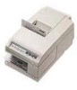
Epson U375 - TM B/W Dot-matrix Printer Manual
 |
UPC - 000001690262
View all Epson U375 manuals
Add to My Manuals
Save this manual to your list of manuals |
Epson U375 manual content summary:
- Epson U375 | User Manual - Page 1
TM-U375/U375P User's Manual 400391309 - Epson U375 | User Manual - Page 2
Printer Part Names (1) Printer cover (2) Control panel (3) Power switch (4) Take-up spool (5) Display module connector (6) Interface connector (7) Drawer kick-out connector (8) Power connector (9) DIP switches (under a cover) (10) Cover open recess Control Panel VALIDATION/SLIP - Epson U375 | User Manual - Page 3
Seiko Epson Corporation assumes no responsibility for errors repairs, or alterations to this product, or (excluding the U.S.) failure to strictly comply with Seiko Epson Corporation's operating and maintenance instructions. Seiko Epson Corporation shall not be liable against any damages or problems - Epson U375 | User Manual - Page 4
applied only to the printers that are so labeled. (EMC is tested using the Epson power supplies.) Europe: CE marking tested and found to comply with the limits for a Class A digital device, pursuant to Part and used in accordance with the instruction manual, may cause harmful interference to radio - Epson U375 | User Manual - Page 5
(for the TM-U375 only). Ct Bidirectional parallel interface in accordance with the IEEE 1284 Nibbe/Byte Modes. About This Manual Setting up and Using El Chapter 1 contains information on unpacking the printer, setting it up, setting the DIP switches, and adjusting the paper near end detector - Epson U375 | User Manual - Page 6
Cl Chapter 4 contains specifications. Notes, Cautions, and Warnings 0 Note: % Notes have important information and useful tips on the operation of your printer. CAUTION: Cautions must be observed to avoid minor injury to yourself or damage to your equipment. WARNING: Warnings must be followed - Epson U375 | User Manual - Page 7
-test with the slip paper 1-18 Running the self-test with validation paper l-19 Setting the DIP Switches l-20 TM-U375 DIP-switch functions l-21 TM-U375P DIP-switch functions l-22 Adjusting the Paper Roll End Sensing Position l-23 Using the Power Switch Cover l-25 Chapter 2 Using the Printer - Epson U375 | User Manual - Page 8
3 Troubleshooting Troubleshooting 3-2 General problems 3-2 Printing problems 3-2 Paper handling problems 3-4 Hexadecimal Dumping 3-6 Starting hexadecimal dumping 3-6 Ending hexadecimal dumping 3-7 Chapter 4 Reference Information Printing Specifications 4-2 Character Specifications 4-2 Paper - Epson U375 | User Manual - Page 9
Chapter 1 Setting Up the Printer Setting Up the Printer 1-1 - Epson U375 | User Manual - Page 10
Unpacking The illustration below shows the items included for the standard specification printer. Take-up spool Paper roll (1 pc) Ribbon cassette Power switch cover Removing the Protective Materials The printer is protected during shipping by protective materials that must be removed before you - Epson U375 | User Manual - Page 11
Protective material , Note: % Store the protective material A on the back of the printer, following the steps below. 1. Insert the projections on the protective material A into the corresponding protective material A back in its original position if you ever ship or store your printer. Setting Up the - Epson U375 | User Manual - Page 12
http://www.epsonexpert.com/ and follow the on-screen instructions. For customers in other countries, go to the following web site: http://www.epson-pos.com/ Connecting the Printer to Your Computer TM-U375 Follow the procedures below only when you use the printer as a single unit (not connected to an - Epson U375 | User Manual - Page 13
Your printer comes with inch-type hexagonal lock screws installed. If you plan the other end of the cable into the computer. TM-U375P You need an appropriate parallel interface cable to connect your computer to the printer. 1. Make sure that the printer and the computer are turned off. Then plug the - Epson U375 | User Manual - Page 14
an intelligent module). (Intelligent module connection is available only for the TM-U375.) When you use the TM-U375 with the intelligent module, refer to the IT-U Series User's Manual for details. Use a drawer that matches the printer specification. Using an improper drawer may damage the drawer as - Epson U375 | User Manual - Page 15
TM-U375 TM-U375P A CAUTIONS: 1. Do not connect a telephone line to the drawer kick out connector. 2. Do not confuse the drawer kick out connector and the display module connector. Setting Up the Printer 1-7 - Epson U375 | User Manual - Page 16
äaligt werden. 1. Stellen Sie sicher, daß der Drucker ausgeschaltet ist. 2. Stecken Sie den Kabelsteckverbinder fest in den AuszugSteckverbinder am Drucker ein, bis er hörbar einrastet. TM-U375 1-8 Setting Up the Printer - Epson U375 | User Manual - Page 17
TM-U375P A ACHTUNG: 1. Am Auszug-Steckverbinder für die Geldlade keine Telefonleitung anschließen. 2. Nicht den Auszug-Steckverbinder für die Geldlade und den Displaymodul-Steckverbinder vetwechseln. Setting Up the Printer 1-9 - Epson U375 | User Manual - Page 18
product other than the display module to the DM connector. 4. If you connect any product other than the display module to the DM connector, Seiko Epson Corporation is not liable for any damage to the other product or to the TM-U375 itself. 1-10 Setting Up the Printer - Epson U375 | User Manual - Page 19
the printer is turned off. 2. Connect the ground wire to the ground connector (marked FG) on the bottom of the printer with the screw provided on the printer. Alternatively, another screw located beside the power connector on the TM-U375P can be used to connect the ground wire. TM-U375 Setting Up - Epson U375 | User Manual - Page 20
EPSON power supply for your printer. When the printer is connected to an intelligent module, the power is supplied by the intelligent module. Refer to the IT-U Series User's Manual for details. (Intelligent module connection is available for the TM-U375 only.) Using an incorrect power supply - Epson U375 | User Manual - Page 21
make sure that the required voltage matches that of your electrical outlet. 3. Plug the power supply's DC cable connector into the printer's power connector as shown below. TM-U375 TM-U375P 4. Plug the power supply's power cord into an electrical outlet. , Note: Qh To remove the DC cable connector - Epson U375 | User Manual - Page 22
cassette may be damaged. Be sure the printer is not receiving data when you replace a ribbon cassette; otherwise data may be lost. * Note: % Use the EPSON ERC-38 ribbon cassette for your printer. 1. Turn on the printer and open the printer cover. 2. Turn the ribbon cassette's knob two or three times - Epson U375 | User Manual - Page 23
Q3.l If the ribbon is not installed correctly, to remove the ribbon cassette, grasp the cassette's tab on the left side, lift the left side out first, and then pull the cassette out of the printer. Repeat steps 2, 3 and 4 above to install the ribbon cassette again. Tab Setting Up the Printer 1 - 1 5 - Epson U375 | User Manual - Page 24
. 4. Insert the tip of the paper into the paper inlet as far as it will go, and push the PAPER LOAD switch to feed the paper roll until the paper comes out from the top of the printer. Note that the arrow in the exploded drawing below points towards the front of the printer. 1-16 Setting Up the - Epson U375 | User Manual - Page 25
paper and reinsert the side of the take-up spool as the illustration below. 2 or c) Install the take-up spool in the printer. 6. Tear off the receipt paper on the cutter; then close the printer cover. , Note: % When the printer cover is open, the PAPER FEED button is inactive. Setting Up the Printer - Epson U375 | User Manual - Page 26
install the ribbon cassette and the paper roll before you run the self test. 1. Make sure the printer is turned off and the printer cover is closed properly. 2. While holding down the PAPER FEED button, turn on the printer to begin the self-test. The self-test prints the printer settings and pauses - Epson U375 | User Manual - Page 27
after the self-test completes. 6. Self-test mode switches to normal mode. , Note: % If you want to pause the self-test for the paper roll, slip paper, or validation paper at any point, press the PAPER FEED button. Press the PAPER FEED button again to resume the self-test. Setting Up the Printer 1-19 - Epson U375 | User Manual - Page 28
your interface and print column settings by changing the DIP switch settings. 1. Make sure the printer is turned off. 2. Remove the screw from the DIP switch cover. Then take off the DIP switch cover, as shown in the illustration below. 3. There are two sets of switches. Notice that ON is marked - Epson U375 | User Manual - Page 29
TM-U375 DIP-switch functions DIP Switch Set 1 SW Function l-1 Data reception error l-2 Receive buffer capacity l-3 Handshaking l-4 Word length 1-5 Parity check l-6 Parity selection l-7 Used Not used Not used Do not change the settings of switch 2-4, 2-5 and 2-6. Setting Up the Printer 1-21 - Epson U375 | User Manual - Page 30
display module connector. 2. DIP switch settings cannot be changed after the power is turned on or after the printer is reset through the interface. When turning the power on, do not change the settings of DIP switches 7 and 8. TM-U375P DIP-switch functions DIP Switch Set 1 SW Function 1-1 Auto - Epson U375 | User Manual - Page 31
%h To attach the DIP switch cover, insert the cover upward then slide the cover leftward, as shown in the illustration below. Adjusting the Paper Roll End Sensing Position The paper near end detector detects when the paper is almost gone by measuring the diameter of the paper roll. Software programs - Epson U375 | User Manual - Page 32
inch) Adjustment position number #l #2 #3 #4 #5 4. Loosen the detector screw with a coin or screwdriver. 5. Set the detector scale to the position you determined from the table by moving the detector screw up or down. The replace the take-up spool and close the printer cover. 1-24 Setting Up the - Epson U375 | User Manual - Page 33
attached by inserting a pointed object (like a ball point pen) through either of the two small holes on the switch cover. Push to attach the cover. If an accident occurs when the power switch cover is attached, unplug the power supply cord from the outlet immediately. Setting Up the Printer 1-25 - Epson U375 | User Manual - Page 34
- Epson U375 | User Manual - Page 35
Chapter 2 Using the Printer Using the Printer 2-1 - Epson U375 | User Manual - Page 36
to release the paper clamp. lndicator lights The control panel lights provide information on printer conditions. POWER (green) The POWER light is on when the printer power is on. ERROR (red) The ERROR light is on or is flashing when the printer is not ready to print. The ERROR light is on under - Epson U375 | User Manual - Page 37
- Epson U375 | User Manual - Page 38
sure to install the paper roll in the printer, even if you plan to print only on slip paper. This will prevent paper jams. 1. Send the appropriate control commands from the computer to print on slip paper. 2. When the VALIDATION/SLIP light flashes, insert a slip into the slip paper inlet as shown in - Epson U375 | User Manual - Page 39
as it will go. * Note: Qb When the VALIDATION/SLIP light flashes (this depends on the application software), remove the paper from the paper path. Replacing the Paper Roll To change the paper roll, follow the steps below. 1. Cut the journal paper on the cutter; then remove the take-up spool. Using - Epson U375 | User Manual - Page 40
of the arrow, as the illustration below. PAPER LOAD switch Never pull out the paper roll manually. 4. Reinstall a new paper roll by following the steps in Installing the Paper Roll in Chapter 1. Replacing the Ribbon Cassette Never turn the ribbon cassette's feed knob in the opposite direction of - Epson U375 | User Manual - Page 41
to the center of the printer and the paper clamp to release. If one of these ways is not used, the ribbon might not be inserted or removed correctly. Removing the ribbon cassette 1. Turn the printer power off and on again; then open the printer cover. 2. Grasp the ribbon cassette's tab on the left - Epson U375 | User Manual - Page 42
two or three times in the direction of the arrow, to take up any slack in the ribbon. or 3 times 2. Insert the ribbon in the position as shown below, and push the ribbon cassette into the printer until it clicks. Then rotate the cassette's knob two or three more times. This is necessary to - Epson U375 | User Manual - Page 43
is installed between the print head and the ribbon mask without wrinkles or creases, as shown below. Print head a* Note: Remove the ribbon cassette from the printer when you store the printer for a long time. CAUTION: Do not use aerosol sprayers containing flammable gas inside or around this product - Epson U375 | User Manual - Page 44
- Epson U375 | User Manual - Page 45
Chapter 3 Troubleshooting Troubleshooting 3-1 - Epson U375 | User Manual - Page 46
AC inlet of the power supply. Make sure that the power supply's power cord is properly plugged into the electrical outlet. Printing problems The ERROR light is on (not flashing) and nothing is printed. If the JOURNAL OUT light is on: The paper roll is not installed, or the paper roll is nearly or - Epson U375 | User Manual - Page 47
work, unplug the power supply cord from the outlet immediately. Then contact a qualified service person. The ERROR light is off but nothing is printed. Try to run the self-test to make sure that the printer works properly. See Self-test later in this section. If the self-test does not work, contact - Epson U375 | User Manual - Page 48
- Epson U375 | User Manual - Page 49
4. Cut the paper roll. 5. Remove the paper jam while pulling the release lever toward you, and pull the paper out in the direction of the arrow as shown in the illustration below. , Notes: Q?l 1. Never pull out the jammed paper in the opposite direction from the ejection side of the printer. 2. Pull - Epson U375 | User Manual - Page 50
hexadecimal format along with a guide section to help you find specific commands. Starting hexadecimal dumping Open the printer cover and turn on the power while pressing the PAPER FEED button, then close the cover. The printer first prints "Hexadecimal Dump" on the paper roll, and prints the data - Epson U375 | User Manual - Page 51
data in this case can be printed by placing the printer in off-line mode by opening the cover or pressing the PAPER FEED button. Example printing Hexadecimal Dump 1B 21 00 1B End hexadecimal dumping by turning off the power or by resetting the printer after printing completes. Troubleshooting 3-7 - Epson U375 | User Manual - Page 52
- Epson U375 | User Manual - Page 53
Chapter 4 Reference Information Reference Information 4-1 - Epson U375 | User Manual - Page 54
Printing Specifications Printing method: Serial impact dot matrix Head wire layout: Serial type 9-pin 1/72 inch Printing direction: Bidirectional, minimum distance printing (logic seeking) Printing speed: Approximately 3.5 LPS (40 columns,16 CPI, continuous printing) Approximately 5.4 LPS (20 - Epson U375 | User Manual - Page 55
2.67 IPS (16 LPS) Paper size: (continuous paper feeding) a) Paper roll Paper width: 76 f 0.5 mm (2.99" ? .02") Outside diameter: l Single-ply paper: Journal paper only: 0 60 + 0 mm (2.36") or less (with take-up flange diameter of o 75 mm (2.95")) Receipt paper only: 0 83 + 0 mm (3.27 - Epson U375 | User Manual - Page 56
Use cut sheets with a paper roll loaded. l Use cut sheet that is flat, without curls, folds, warps, or wrinkles, especially at the paper end. Otherwise, the paper may become ink stained or the ribbon may get caught in the printer mechanism. Especially slip paper with curls at the paper end may cause - Epson U375 | User Manual - Page 57
the areas shown in the figures below must not be used. Otherwise, the paper cannot be detected by the paper detector. Paper that is translucent must not be used. Validation paper Inserting direct1 Slip paper Inserting direction 1' 6 3 E : Srnrn(.3z?) : Holes are prohibited in this area. lOmm(.98 - Epson U375 | User Manual - Page 58
* Be sure to use a safety-standards-applied power source that meets the following specifications. Rated output: 24 V/2.0 A or more, Maximum output: 240 VA or less Electrostatic Protection (measured) based on the IEC801-2 test conditions) Air discharge: 8K V clear level Contact discharge: 4K V - Epson U375 | User Manual - Page 59
, without condensation) Storage: 20 to 90%RH (excluding paper and ribbon, without condensation) temperature Vibration resistance: When packed: Frequency: after the vibration test, and the printer should operate normally. Impact resistance: When packed: Package: Epson standard package Height - Epson U375 | User Manual - Page 60
compatible (Nibble/Byte Modes) Note: Refer to the EPSON TM-U375/U375P Specification for details. Printing on Cut Sheets Use the following procedure to print on slip or validation paper. Step Host Operation Printer Operation 1 Transmit the ESC c 0 Switches to cut sheet mode and waits for a cut - Epson U375 | User Manual - Page 61
cut sheet that is narrower than the carriage movement range, once the printer has been put in the cut sheet mode and the sheet of paper has been inserted, the following operations should be avoided: turning the power supply switch on or off, opening the cover, issuing the return home command (ESC - Epson U375 | User Manual - Page 62
. ASB: wait for cut sheet sensor (ASB 3-5) to be "paper p" (0). 7) To cancel the slip paper waiting state, send DLE ENQ 3. When canceled, the printer returns to paper roll mode, and the 4 bytes of ASB are transmitted. ASB: slip paper state (ASB 4-l) becomes "not selected" (1). 8) Waits for the slip - Epson U375 | User Manual - Page 63
printer has been put in the cut sheet mode and the sheet of paper has been inserted, the following operations should be avoided: turning the power supply switch using Auto Status Back (ASB), however, process the consecutive three-byte code (except for XOFF) as ASB data after confirming the first byte - Epson U375 | User Manual - Page 64
data is printed. The printer cannot print horizontally adjacent dots. Therefore, the printing results may differ even if the same character codes are transmitted, since the dots placed on the borderline between characters differ depending on the DIP switch 2-2 setting. Particularly in line drawings - Epson U375 | User Manual - Page 65
- Epson U375 | User Manual - Page 66
WEEE (Waste Electrical and Electronic Equipment) Directive This information only applies to customers in the European Union, according to Directive 2002/96/EC OF THE EUROPEAN PARLIAMENT AND OF THE COUNCIL OF 27 January 2003 on waste electrical and electronic equipment (WEEE) and legislation - Epson U375 | User Manual - Page 67
bbi szeméttõl elkülönítve helyezze el, és biztosítsa, hogy azt környezetbarát módon újrahasznosítsák. A rendelkezésére álló begyûjtõ létesítményekrõl kérjük tájékozódjon a megfelelõ helyi állami szerveknél vagy a viszonteladónál, ahol a terméket vásárolta. Polski Symbol przekreślonego kosza znajduj - Epson U375 | User Manual - Page 68
Printed in Japan
-
 1
1 -
 2
2 -
 3
3 -
 4
4 -
 5
5 -
 6
6 -
 7
7 -
8
-
9
-
10
-
11
-
12
-
13
-
14
-
15
-
16
-
17
-
18
-
19
-
20
-
21
-
22
-
23
-
24
-
25
-
26
-
27
-
28
-
29
-
30
-
31
-
32
-
33
-
34
-
35
-
36
-
37
-
38
-
39
-
40
-
41
-
42
-
43
-
44
-
45
-
46
-
47
-
48
-
49
-
50
-
51
-
52
-
53
-
54
-
55
-
56
-
57
-
58
-
59
-
60
-
61
-
62
-
63
-
64
-
65
-
66
-
67
-
68
 |
 |

TM-U375/U375P
User’s Manual
400391309