Frigidaire FGEW2745KB Installation Instructions (All Languages)
Frigidaire FGEW2745KB - Gallery 27" Convection Single Oven Manual
 |
UPC - 057112102054
View all Frigidaire FGEW2745KB manuals
Add to My Manuals
Save this manual to your list of manuals |
Frigidaire FGEW2745KB manual content summary:
- Frigidaire FGEW2745KB | Installation Instructions (All Languages) - Page 1
Electrical Junction Box 318259704 (black models), 318259705 (bisque * Suggested distance from floor is 31" (78.7cm). models) or 318259707 (stainless steel models). Minimum required distance is 4 ½" (11.4cm). Figure 1 27" and 30" Single Wall Ovens (Double ovens see Figure 2) PRODUCT DIMENSIONS - Frigidaire FGEW2745KB | Installation Instructions (All Languages) - Page 2
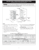
the built-in oven. If the oven larger inferior trim through a Service Center. decorative trim does not butt against the cabinet, or if noise is heard on convection models, verify dimension G to assure it is according to the required dimension. Figure 2 27" AND 30" DOUBLE OVENS (Single Ovens - Frigidaire FGEW2745KB | Installation Instructions (All Languages) - Page 3
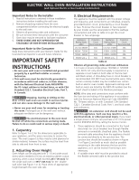
Keep these instructions with your Owner's Guide for the local electrical inspector's use and future reference. IMPORTANT SAFETY INSTRUCTIONS • Be sure your wall oven is installed and grounded properly by a qualified installer or service technician. • This wall oven must be electrically grounded in - Frigidaire FGEW2745KB | Installation Instructions (All Languages) - Page 4
ELECTRIC WALL OVEN INSTALLATION INSTRUCTIONS (and Optional Electric or Gas Cooktop Combination) Electrical Shock Hazard • Electrical ground is required on this appliance. • Do not connect to the electrical Electrical Code, Part 1, and local codes and ordinances. Risk of electrical a new branch - Frigidaire FGEW2745KB | Installation Instructions (All Languages) - Page 5
ELECTRIC WALL OVEN INSTALLATION INSTRUCTIONS (and Optional Electric or Gas Cooktop Combination) If oven is used in a new branch circuit the oven and visible when the door is opened. When ordering parts for or making inquires about your oven, always be sure to include the model and serial - Frigidaire FGEW2745KB | Installation Instructions (All Languages) - Page 6
ELECTRIC WALL OVEN INSTALLATION INSTRUCTIONS (and Optional Electric or Gas Cooktop Combination) 6 Install the Anti-tip Mounting Screws The wall oven can tip when the door is open. The anti-tip mounting screws supplied with the wall oven must be installed to prevent tipping of the wall oven and - Frigidaire FGEW2745KB | Installation Instructions (All Languages) - Page 7
ELECTRIC WALL OVEN INSTALLATION INSTRUCTIONS (and Optional Electric or Gas Cooktop Combination) For typical under counter installation of an electric built-in oven see Figure below. Only certain cooktop models may be installed over certain built-in electric oven models. Approved cooktops and built- - Frigidaire FGEW2745KB | Installation Instructions (All Languages) - Page 8
Outlet Pressure Regulator Manual Shutoff Valve 4"(10 cm) Right Side of Cabinet (To be accessible for shut-off valve operation) Figure 9 - TYPICAL UNDER COUNTER INSTALLATION OF A SINGLE ELECTRIC BUILT-IN OVEN WITH A GAS COOKTOP ABOVE 6. Leveling the Wall Oven 1. Install an oven rack in the - Frigidaire FGEW2745KB | Installation Instructions (All Languages) - Page 9
será necesario. Canadá Estados Unidos No quite los separadores de los muros laterales o/y de la parte posterior del horno empotrado. Estos espaciadores centran el horno en el espacio provisto. El horno debe estar centrado para prevenir una concentración excesiva de calor que podría resultar en da - Frigidaire FGEW2745KB | Installation Instructions (All Languages) - Page 10
eléctrica o de gas facultativa) No quite los separadores de los muros laterales o/y de la parte posterior del horno empotrado. Estos espaciadores centran el horno en el espacio provisto. El horno debe estar centrado para prevenir una concentración excesiva de calor que podría resultar en daños por - Frigidaire FGEW2745KB | Installation Instructions (All Languages) - Page 11
contenidas en este manual antes de instalar el horno. 2. Saque todo el material usado en el embalaje del compartimiento del horno antes de conectar con el estándar CSA canadiense C22.1 , código eléctrico canadiense, parte 1, y códigos y ordenanzas locales. No se debera usar extensiones para enchufar - Frigidaire FGEW2745KB | Installation Instructions (All Languages) - Page 12
, asegúrese de que el horno llegue a su destino final como mínimo tres (3) horas antes de encenderlo. Si se enciende el horno cuando aún está frío, se en los Estados Unidos, o el Código Eléctrico Canadiense CSA Standard C22.1, Part 1, en Canadá. Riesgo de choque eléctrico (El no prestar atención a - Frigidaire FGEW2745KB | Installation Instructions (All Languages) - Page 13
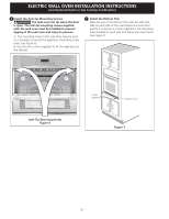
. 2 Buscar los tornillos que se incluyen en el paquete de literatura. 3 Insertar el horno en la abertura del gabinete. Deslizar el horno hacia dentro dejando 1½" (3,8 cm) de espacio libre entre el horno y la parte delantera del gabinete (ver la Figura 5). 4 Empujar el cable blindado a través del - Frigidaire FGEW2745KB | Installation Instructions (All Languages) - Page 14
para colocar la unidad en la cabina. 7 Instalación de la Guarnición Inferior: Colocar la parte superior de la guarnición inferior sobre las lengüetas laterales del horno, debajo de la puerta del horno, y fijarlas usando los 2 tornillos provistos con los orificios de montaje ubicados a cada lado del - Frigidaire FGEW2745KB | Installation Instructions (All Languages) - Page 15
del gabinete debe permitir la instalación de modelos de tapas de cocina aprobados. Para reducir el riesgo de lesiones personales y inclinación del horno de pared, éste debe asegurarse a los gabinetes mediante soportes de montaje. Approx. 3" (7.5 cm) G 36" Min. (91.4cm) Min. H 208/240 caja de - Frigidaire FGEW2745KB | Installation Instructions (All Languages) - Page 16
llenador Gabinete del horno de pared Regulador de presión Válvula de cierre manual 4"(10 cm) Lado horno. 1. Extraer todos los elementos de la parte interior del horno. 2. Encender el horno (Consular la Guía de Uso y Cuidado.) 3. Verificar el funcionamiento de los controles electrónicos del horno - Frigidaire FGEW2745KB | Installation Instructions (All Languages) - Page 17
INSTRUCTIONS des dommages. NOTE: 1. La base doit pouvoir supporter 150 lbs (68 kg) pour les modè largeur si nécessaire un Centre de service et demandant la pièce #318259703 27" et 30" (Pour les fours encastrés doubles voir la figure 2) DIMENSIONS DE L'APPAREIL MODÈLE A B C D 27" (68.6 cm) - Frigidaire FGEW2745KB | Installation Instructions (All Languages) - Page 18
INSTRUCTIONS (7.6 cm) Max. Boîte de jonction NOTES: si nécessaire 1.La base doit pouvoir supporter 300 lbs (136 kg) pour 4. Si la hauteur de découpage est plus grande que si un bruit se fait entendre sur service. les modèles à convection, vérifiez la dimension G pour vous assurer qu'elle est - Frigidaire FGEW2745KB | Installation Instructions (All Languages) - Page 19
de laisser ces instructions au consommateur. 5. de l'appareil, selon le National Electrical Code ANSI/NFPA No. 70, service et en demandant le kit quelles sont les dimensions applicables à votre modèle, #903056-9010. ainsi que l'espace nécessaire pour recevoir l'appareil. La surface qui supporte - Frigidaire FGEW2745KB | Installation Instructions (All Languages) - Page 20
la mise à la terre de l'appareil. Si vous ne respectez pas toutes les instructions précédentes, un feu, des blessures corporelles ou un choc électrique peuvent en ré que l'installation électrique est adéquate et conforme avec le National Electrical Code ANSI/NFPA No. 70-dernière édition, ou avec la - Frigidaire FGEW2745KB | Installation Instructions (All Languages) - Page 21
• Soyez 2 personnes ou plus pour installer ou déplacer l'appareil. • Des blessures ou des dommages à l'appareil peuvent survenir si vous ne suivez pas cette instruction. 1 Déballez le four encastré et récupérez la moulure inférieure qui est fixée sur le côté du four 2 Localisez les vis de fixation - Frigidaire FGEW2745KB | Installation Instructions (All Languages) - Page 22
INSTRUCTIONS D'INSTALLATION POUR FOUR ENCASTRÉ ÉLECTRIQUE (Combiné à une table de cuisson électrique ou à gaz (en option)) 6 Installez les vis de fixation Le four encastré peut basculer - Frigidaire FGEW2745KB | Installation Instructions (All Languages) - Page 23
dans l'enveloppe de littérature ainsi que le feuillet d'instructions d'installation de la table de cuisson pour les dimensions). Pour réduire les risques de blessures et pour empêcher le four encastré de basculer. Utilisez les supports de fixation pour retenir le four encastré à l'armoire. Approx - Frigidaire FGEW2745KB | Installation Instructions (All Languages) - Page 24
re tourne. Le ventilateur convection arrête lorsque l'on ouvre la porte du four. Avant d'appeler le service d'entretien Réviser la liste de vérifications préventives et les instructions d'opération dans votre Manuel d'utilisation et d'entretien. Vous sauverez probablement du temps et de l'argent. La
-
 1
1 -
 2
2 -
 3
3 -
 4
4 -
 5
5 -
 6
6 -
 7
7 -
8
-
9
-
10
-
11
-
12
-
13
-
14
-
15
-
16
-
17
-
18
-
19
-
20
-
21
-
22
-
23
-
24
 |
 |
ELECTRIC WALL OVEN INSTALLATION INSTRUCTIONS
(and Optional Electric or Gas Cooktop Combination)
B
A
D
C
H
F
I
G
27 3/16”
(69.1 cm)
2”
(5.1 cm)
Min.
31”*
(78.7 cm)
3”
(7.6 cm)
1½” (3.8 cm)
Min.
2" (5 cm) Wide Wood
Spacer if Needed
Door Open
(see note 2)
Spacer
Electrical
Junction Box
Hole for
Cable
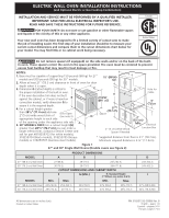
Figure 1
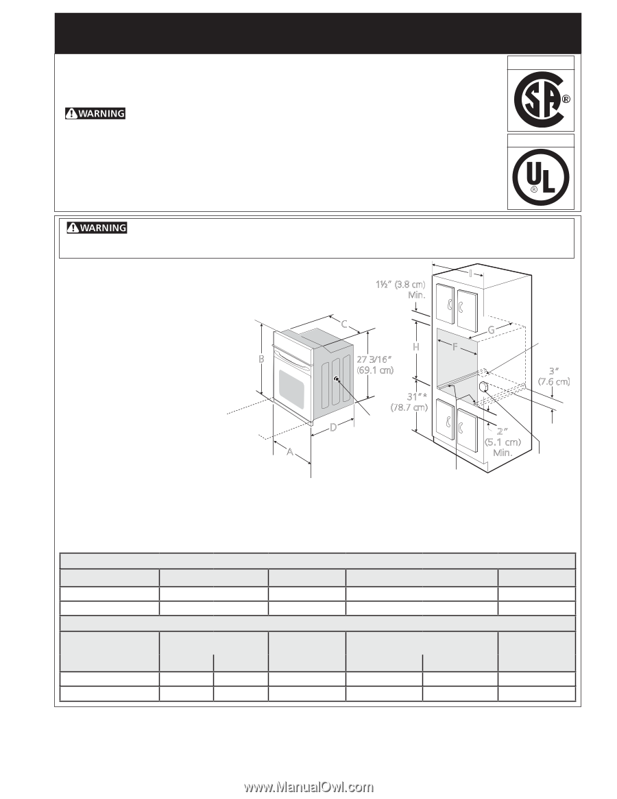
27" and 30" Single Wall Ovens (Double ovens see Figure 2)
P/N 318201532 (0908) Rev. B
English – pages 1-8
Español – páginas 9-16
Français -pages 17-24
All dimensions are in inches (cm).
Do not remove spacers (if equipped) on the side walls and/or on the back of the built-
in oven. These spacers center the oven in the space provided. The oven must be centered to prevent
excess heat buildup that may result in heat damage or fire.
NOTES:
1.
Base must be capable of supporting 150 pounds (68 kg) for 27"
models and 200 pounds (90 kg) for 30" models.
2.
Allow at least 21" (53.3 cm) clearance in front of oven for door
depth when it is open.
of the opening under the appliance side rails.
5.
30" MODELS ONLY:
For a cutout height
(H)
greater than
28
5
/
8
" (72.7 cm)
you can order a
larger inferior trim, contact a Service Center and
ask for part #318259703 (for white models),
318259704 (black models), 318259705 (bisque
models) or 318259707 (stainless steel models).
3.
Dimension
G
(cutout depth)
is critical to
the proper installation of the built-in oven.
If the oven decorative trim does not butt
against the cabinet, or if noise is heard on
convection models, verify dimension
G
to
assure it is the required depth.
4.
For a cutout height greater
than
28
1
/
8
"
(71.4 cm)
add one
2"(5 cm) wide wood shim of
appropriate height to each side
Printed in United States
* Suggested distance from floor is 31" (78.7cm).
Minimum required distance is 4 ½" (11.4cm).
INSTALLATION AND SERVICE MUST BE PERFORMED BY A QUALIFIED INSTALLER.
IMPORTANT: SAVE FOR LOCAL ELECTRICAL INSPECTOR'S USE.
READ AND SAVE THESE INSTRUCTIONS FOR FUTURE REFERENCE.
FOR YOUR SAFETY: Do not store or use gasoline or other flammable vapors
and liquids in the vicinity of this or any other appliance.
Your new wall oven has been designed to fit a limited variety of cutout sizes to make
the job of installing easier. The first step of your installation should be to measure your
current cutout dimensions and compare them to the cutout dimensions chart below for
your model. You may find little or no cabinet work being necessary.
Canada
United States
PRODUCT DIMENSIONS
MODEL
A
B
C
D
27" (68.6 cm) Wall Oven
27 (68.6)
29 (73.7)
24
5
/
8
(62.5)
24½ (62.2)
30" (76.2 cm) Wall Oven
30 (76.2)
29 (73.7)
28¼ (71.8)
24½ (62.2)
CUTOUT DIMENSIONS AND CABINET WIDTH
F
G (Min.)
H. Standard Height
(**Others, see notes 4 & 5)
I
MODEL
Min.
Max.
Min.
Max
.
27" (68.6 cm) Wall Oven
24
7
/
8
(63.2)
25¼ (64.1)
23½ (59.7)
27¼ (69.2)
28
5
/
8
(72.7)
27
1
/
8
(68.9) Min
30" (76.2 cm) Wall Oven
28½ (72.4)
29 (73.7)
23½ (59.7)
27¼ (69.2)
28
5
/
8
(72.7)
30
1
/
8
(76.5) Min