Frigidaire FGIP2468UF Wiring Diagram
Frigidaire FGIP2468UF Manual
 |
View all Frigidaire FGIP2468UF manuals
Add to My Manuals
Save this manual to your list of manuals |
Frigidaire FGIP2468UF manual content summary:
- Frigidaire FGIP2468UF | Wiring Diagram - Page 1
) To start: Press START/CANCEL and close the door. WATER/SERVICE TEST To activate the Water/ Service Test, cycle the circuit breaker to put the unit in Power Failure Mode. Simultaneously press "DRY" and START/CANCEL for 1 second. The dishwasher will then step through the test cycle per the chart - Frigidaire FGIP2468UF | Wiring Diagram - Page 2
Assy. may vary from your model) Pump Assembly The pump assembly actuator. TROUBLE SHOOTING TIPS WARNING Personal Injury Hazard Always disconnect the dishwasher from the Connect to a vented drain. 1. Instruct customer/user 2. Instruct customer/user 3. Instruct customer/user on proper loading of
-
 1
1 -
 2
2
 |
 |
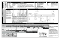
SERVICE DATA SHEET
Electronic Series
This information is intended for use by persons having electrical and
mechanical training and a level of knowledge of these subjects generally
considered acceptable in the appliance repair trade.
Electrolux Home
Products North America cannot be responsible, nor assume any liability,
for injury or damage of any kind arising from the use of this Service
Data Sheet.
BK
............
Black
BU
............
Blue
PK
............
Pink
R
..............
Red
Viol
..........
Violet
W
.............
White
Y-BK
.........
Yellow/BK
R-Y
............
Red/Yellow
BK-W
........
Black/White
R-W
...........
Red/White
1
2
On display upon detection of
failure
Note: End State remains in effect until door is opened
COLOR CODE
OPERATION
DISPLAY CODES (READOUT)
DISPLAY CODES (LED)
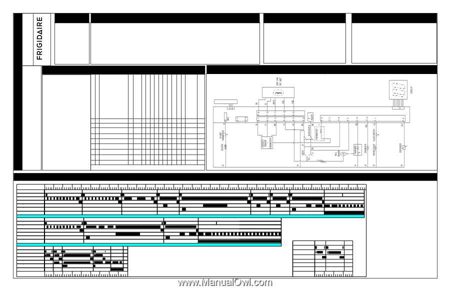
WIRING DIAGRAM
WATER/SERVICE TEST
CYCLE SELECTION OPTIONS
The dishwasher responds to user inputs only when its door is open.
To select a new
cycle or option:
Press to select desired cycle and/or option (indicator lights will change).
To delay start :
Press DELAY START repeatedly until the desired delay time is displayed.
For controls
lock:
Press and hold DELAY START for 3 seconds (its LED will illuminate when lock is
set)
To start:
Press START/CANCEL and close the door.
Er
Switch failure (shorted keypad)
Th
Open/shorted thermistor
Tu
Open/shorted turbidity sensor
hS
Pump rpm error
Uo
Vent stuck open
uC
Vent stuck closed
uF
Vent rpm too low or stopped
All LEDs illuminate during Power Failure
CLOSE DOOR will scroll indicating to close and
latch the door
Delay
Displayed when unit is counting
down a delay
Clean
Displayed to indicate the cycle is
complete
Sanitize
Displayed to indicate sanitiziation
was achieved
To activate the Water/
Service Test, cycle the
circuit breaker to put the
unit in Power Failure Mode.
Simultaneously press “DRY”
and START/CANCEL for 1
second.
The dishwasher will then
step through the test cycle
per the chart.
If START/
CANCEL is pressed during
the test the current step
is terminated and the test
advances to the next cycle
step.
- 3
1
1
1
1
1
1
1
1
1
1
1
1
1
- 6
2
2
2
2
2
2
2
2
- 4
TACTILE
TOP
SWITCH
Description
Interval Number
Fill Number
3
1
1
1
4
1
5
1
6
1
7
1
8
1
9
1
Fill/Det. Dispenser
Fill
Wash/Heat/Det.Disp.
Pause/Heat
Wash/Heat
Wash/Heat/Det.Disp.
Drain
Dry
End State
60
Interval Duration Sec.
27
45
0.4
75
60
90
90
Motor Speed (rpm)
0
0
3400
0
2800
3400
0
0
0
Water Vavle
Circulation Motor
Drain Motor
Heater
Dispenser
Blower
Washing LED
Drying LED
Sanitize LED
Clean LED
Monitored Device
1
1
1
1
1
1
1
1
1
1
1
1
1
0
1
1
1
1
1
1
1
1
1
fan
damper
turbidity
hall
sensor
thermistor
fan speed
fan
damper
uo
tu
hS
th
uF
uC
0
0
0
0
0
0
0
0
0
0
0
0
0
0
0
0
0
0
0
0
0
0
0
0
0
0
0
0
1
0
0
0
0
0
0
0
0
0
0
0
0
0
0
0
0
0
0
0
0
0
0
0
0
0
0
0
0
0
0
0
0
0
0
0
0
0
0
P/N: A13762001 Rev. B
Artwork: A13762001 Rev. 002
Pre-Wash 1
Normal
Water Valve
Normal
5
10
15
20
25
30
35
40
45
50
55
60
65
70
75
80
85
90
95
100
105
110
115
120
125
130
135
5
10
15
20
25
30
35
40
45
Pre-Wash 2
Pre-Wash 3
Main Wash
Rinse 1
Final Rinse
Dry
Vent
Circulation Motor
Drain Motor
Heater
Dispenser
Water Valve
Vent
Circulation Motor
Drain Motor
Heater
Dispenser
Pre-Wash 1
Main Wash
Final Rinse
Dry
Minutes
Quick Wash
Minutes
Water Valve
Vent
Circulation Motor
Drain Motor
Heater
Dispenser
PW 1
PW 2
Main Wash
Final Rinse
Dry
140
145
(Heavy Soils)
(Extra-light Soils)
(Heated Dry)
150
155
160
165
170
175
Pre-Wash 4
Rinse 2
Rinse Only
Water Valve
Circulation Motor
Drain Motor
Heater
Dispenser
Vent
Minutes
5
10
15
20
PW 1
PW 2
NOTE:
1.
In all cycles except Rinse Only and
Quick Wash the main wash and final rinse
may be lengthened when needed to reach
optimal temperatures.
2.
If Normal Wash is hte first cycle
run after applying power the heavy
soil response shown here will result.
Thereafter, the sensor will be calibrated.
Then, the cycle will automatically adjust
to the amount of food soil by running only
as many of the pre-washes or pre-rinses
as appropriate.
Normal Wash will run the
extra-light soil response shown here when
ran empty or with dishware having extra-
light or no soils are installed.
3.
In the Quick Wash and Rinse Only
cycles it is normal for the circulaion pump
to pulse during fills.