Frigidaire GLFC2528FW Wiring Schematic - Page 1
Frigidaire GLFC2528FW - 24.9 cu. Ft. Manual Defrost Chest Freezer Manual
 |
UPC - 012505223785
View all Frigidaire GLFC2528FW manuals
Add to My Manuals
Save this manual to your list of manuals |
Page 1 highlights
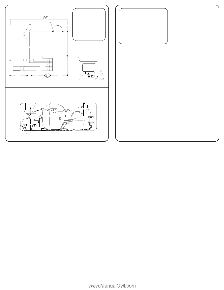
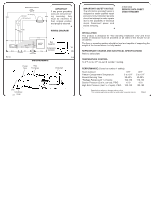
ELECTRICAL CIRCUIT Power L N IMPORTANT If any green grounding See Diagram wires are removed dur- Black Thermistor White ing servicing, they VR/Cold Control must be returned to Compressor their original position and properly secured. Red Gray Purple Blue WIRING DIAGRAM Black User Interface Black EC106 White Brown Yellow Blue Orange Electronic Module Red Lid Switch Interior Light White Run Capacitor Compressor Controller SYSTEM SCHEMATIC Charge Tube Heat Exchanger Discharge Yel Wh C10 Drier Condenser SP27 Outlet IMPORTANT SAFETY NOTICE The information provided herein is designed to assist qualified repair personnel only. Untrained persons should not attempt to make repairs due to the possibility of electrical shock. Disconnect power cord before servicing. 216901200 SERVICE DATA SHEET CHEST FREEZER INSTALLATION This product is designed for "free standing installation only" and three inches of clearance must be provided on all sides of the freezer for air circulation. The floor or mounting surface should be level and capable of supporting the weight of the freezer when it is fully loaded. REFRIGERANT CHARGE AND ELECTRICAL SPECIFICATIONS Refer to serial plate. TEMPERATURE CONTROL 14.0°F cut in, 0°F cut-out @ number 1 setting. PERFORMANCE (Control at number 1 setting) Room Ambient Freezer Compartment Temperature Percent Running Time *Wattage Range (Last 1⁄3 of cycle) Suction Pressure (Cut-in, cut-out), PSIG High Side Pressure (Last 1⁄3 of cycle), PSIG 70°F 5 to 12°F 30-40% 100-140 15-0 105-125 90°F 5 to 12°F 45-55% 110-145 15-0 155-165 Specifications subject to change without notice. *For complete performance data by model refer to service manual. PD642
-
 1
1 -
 2
2
 |
 |