Garmin GMR 1224 xHD2 Installation Instructions
Garmin GMR 1224 xHD2 Manual
 |
View all Garmin GMR 1224 xHD2 manuals
Add to My Manuals
Save this manual to your list of manuals |
Garmin GMR 1224 xHD2 manual content summary:
- Garmin GMR 1224 xHD2 | Installation Instructions - Page 1
contains no user-serviceable parts, and should be opened only by a Garmin® authorized service technician. Any damage install this device. For instructions on updating the software, see your chartplotter owner's manual at support.garmin.com. Tools Needed GUID-55353194-2BBE-4506-B02B-20D5AC5EA950 v6 - Garmin GMR 1224 xHD2 | Installation Instructions - Page 2
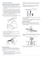
Installation Procedures Preparing the Surface and the Radar for Mounting Before you can mount the radar, you must choose a suitable mounting location (Mounting Considerations, page 1). 1 Secure the included mounting template to the surface at the mounting location, along the bow-stern axis, as - Garmin GMR 1224 xHD2 | Installation Instructions - Page 3
4 Torque the hex bolts to 0.81 kgf-m (70 lfb-in. [6 lbf-ft.]) to fasten the antenna to the pedestal without damaging the antenna or the mounting hardware. Wiring and Connection Considerations It may be necessary to drill 32 mm (11/4 in.) holes for routing the power, network, or grounding cables. • - Garmin GMR 1224 xHD2 | Installation Instructions - Page 4
functions of this radar are controlled with your Garmin chartplotter. See the Radar section of your chartplotter's owner's manual for operating instructions. To download the latest manual, go to support.garmin.com. If you have more than one radar on your boat, you must be viewing the radar screen - Garmin GMR 1224 xHD2 | Installation Instructions - Page 5
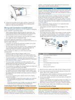
Setting the Front-of-Boat Offset Before you can set the front-of-boat offset, you must measure the potential front-of-boat offset. The front-of-boat offset setting configured for use in one radar mode is applied to every other radar mode and to the Radar overlay. 1 From a Radar screen or the Radar - Garmin GMR 1224 xHD2 | Installation Instructions - Page 6
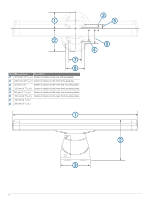
Item Measurement Description 181.8 mm (7 3/16 in.) Center of rotation to the rear of the pedestal. 236.2 mm (9 5/16 in.) Center of rotation to the front of the pedestal. 25 mm (1 in.) Center of rotation to the inner rear mounting holes. 125 mm (4 15/16 in.) 50 mm (1 15/16 in.) 150 mm (5 29/32 - Garmin GMR 1224 xHD2 | Installation Instructions - Page 7
Extensions section of these instructions to make sure the can help troubleshoot installation problems. Status LED support for assistance. Contacting Garmin Support • Go to support.garmin.com for help and information, such as product manuals, frequently asked questions, videos, and customer support - Garmin GMR 1224 xHD2 | Installation Instructions - Page 8
© 2016 Garmin Ltd. or its subsidiaries support.garmin.com
-
 1
1 -
 2
2 -
 3
3 -
 4
4 -
 5
5 -
 6
6 -
 7
7 -
8
 |
 |
GMR
™
420/620/1220/2520
XHD2
SERIES
INSTALLATION
INSTRUCTIONS
Important Safety Information
WARNING
Failure to follow these warnings, cautions, and notices could
result in personal injury, damage to the vessel or device, or poor
product performance.
See the
Important Safety and Product Information
guide in the
product box for product warnings and other important
information.
The radar transmits electromagnetic energy. To avoid possible
personal injury, damage to the vessel or device, or poor product
performance, ensure that the radar is installed according to the
recommendations in these instructions and that all personnel
are clear of the path of the radar beam before transmitting.
When properly installed and operated, the use of this radar
conforms to the requirements of ANSI/IEEE C95.1-1992
Standard for Safety Levels with Respect to Human Exposure to
Radio Frequency Electromagnetic Fields.
To avoid possible personal injury, do not look directly at the
antenna at close range when the radar is transmitting. Eyes are
the most sensitive part of the body to electromagnetic energy.
When connecting the power cable, do not remove the in-line
fuse holder. To prevent the possibility of injury or product
damage caused by fire or overheating, the appropriate fuse
must be in place as indicated in the product specifications. In
addition, connecting the power cable without the appropriate
fuse in place voids the product warranty.
CAUTION
This device should be used only as a navigational aid. Using the
device for any purpose requiring precise measurement or
direction, distance, location, or topography may result in
personal injury or damage to the vessel.
To avoid possible personal injury, always wear safety goggles,
ear protection, and a dust mask when drilling, cutting, or
sanding.
Opening the device may result in personal injury and/or damage
to the device. This device contains no user-serviceable parts,
and should be opened only by a Garmin
®
authorized service
technician. Any damage resulting from opening the unit by
anyone other than a Garmin authorized service technician will
not be covered by the Garmin warranty.
NOTICE
When drilling or cutting, always check what is on the opposite
side of the surface to avoid damaging the vessel.
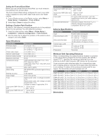
Software Update
You must update the Garmin chartplotter software when you
install this device. For instructions on updating the software, see
your chartplotter owner's manual at
support.garmin.com
.
Tools Needed
•
#2 Phillips screwdriver
•
5 mm hex wrench
•
Drill and 15.0 mm (
19
/
32
in.) drill bit
•
17 mm (
21
/
32
in.) wrench and torque wrench
•
A length of 3.31 mm² (12 AWG) copper wire to ground the
radar housing (and voltage converter, if applicable).
•
Marine sealant
Mounting Considerations
When selecting a mounting location, observe these
considerations.
•
It is highly recommended that the device is mounted out of
range of people, with the vertical beam width above head
height. To avoid exposure to harmful radio frequency (RF)
levels, the device should not be mounted closer to people
than the maximum safe distance value listed in the product
specifications.
•
The device should be mounted high above the ship’s keel
line with minimal blockage of the radar beam. Obstructions
may cause blind and shadow sectors or generate false
echoes. The higher the installation position, the farther the
radar can detect targets.
•
The device should be mounted on a flat surface or a platform
that is parallel to the vessel's water line and is sturdy enough
to support the device's weight. The weight for each model
and antenna is listed in the product specifications.
•
The device must be mounted in a location where it can be
connected to power, water ground, and the Garmin Marine
Network (
Wiring and Connection Considerations
, page 3
).
•
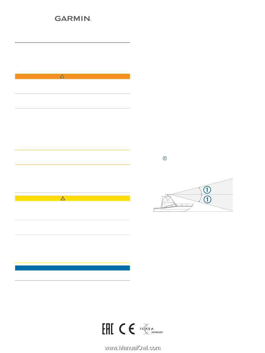
The radar beam spreads vertically 11.5° above and
11.5° below
the radar's radiating element. On vessels with
higher bow angles at cruise speed, the installation angle can
be lowered to point the beam slightly downward to the
waterline while at rest. Shims can be used if necessary.
•
The device should be mounted away from heat sources, such
as smoke stacks and lights.
•
The device should be mounted at a different level than
horizontal spreaders and mast crosstrees.
•
To avoid interference with a magnetic compass, the device
should not be mounted closer to a compass than the
compass-safe distance value listed in the product
specifications.
•
Other electronics and cables should be mounted more than
2 m (6.5 ft.) from the radar beam path.
•
GPS antennas should be either above or below the radar
beam path.
•
The device should be mounted at least 1 m (40 in.) from any
transmitting equipment.
•
The device should be mounted at least 1 m (40 in.) away
from cables carrying radio signals such as VHF radios,
cables, and antennas.
•
The device should be mounted at least 2 m (6.5 ft.) away
from Single Side Band (SSB) radios.
TA-2013/1848
GUID-55353194-2BBE-4506-B02B-20D5AC5EA950 v6
August 2020