GE JVM1790SK Service Manual
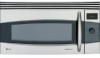
GE JVM1790SK - Profile 1.7 cu. Ft. Convection Microwave Manual
 |
UPC - 084691123453
View all GE JVM1790SK manuals
Add to My Manuals
Save this manual to your list of manuals |
GE JVM1790SK manual content summary:
- GE JVM1790SK | Service Manual - Page 1
Microwave Oven Service Manual JVM1790BK/CK/SK/WK CAUTION BEFORE SERVICING THE UNIT, READ THE SAFETY PRECAUTIONS IN THIS MANUAL. - GE JVM1790SK | Service Manual - Page 2
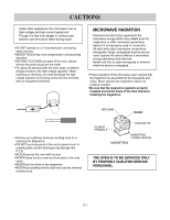
of hinges and latches, (5) evidence of dropping or abuse. c. Before turning on microwave power for any service test or inspection within the microwave generating compartments, check the magnetron, wave guide or transmission line, and cavity for proper alignment, integrity, and connections. d. Any - GE JVM1790SK | Service Manual - Page 3
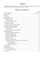
1-1 CAUTIONS 2-1 INSTALLATIONS 3-1 OPERATING INSTRUCTIONS 4-1 CONTROL PANEL 4-1 CONTROL PANEL INSTRUCTIONS 4-2 OVERALL CIRCUIT DIAGRAM 5-1 SCHEMATIC DIAGRAM 5-1 MATRIX CIRCUIT FOR TOUCH KEY BOARD 5-2 GENERAL INFORMATION FOR SERVICE 6-1 GENERAL PRECAUTIONS IN USE 6-1 TRIAL OPERATION - GE JVM1790SK | Service Manual - Page 4
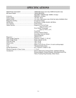
) Tray Tempered Safety Glass Overall Dimensions 2915/16"(W)x167/16"(H)x153/8"(D) Effective Capacity of Oven Cavity 1.7 Cu.ft. Accessories Owner's Manual & Cooking Guide, Installation Manual, Exhaust Adapter, Exhaust Damper, Mounting Kit and Two Filters, Rotating Ring Assembly, Metal Racks. 1-1 - GE JVM1790SK | Service Manual - Page 5
around the dome of the tube whenever installing the magnetron. • Remove your watches whenever working close to or replacing the Magnetron. • DO NOT touch any parts of the control panel circuit. A resulting static electric discharge may damage this P.C.B. • NEVER operate the oven with no load - GE JVM1790SK | Service Manual - Page 6
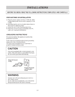
THE FOLLOWING INSTRUCTIONS COMPLETELY AND CAREFULLY. PRECAUTIONS ON INSTALLATION A. Plug the power supply cord into a 120V AC, 60Hz, single-phase power source with a capacity of 15A or 20A. B. Avoid placing the unit in a location where there is direct heat or splashing water. C. Install the unit - GE JVM1790SK | Service Manual - Page 7
OPERATING INSTRUCTIONS CONTROL PANEL For Model: JVM1790BK JVM1790CK JVM1790SK JVM1790WK 4-1 - GE JVM1790SK | Service Manual - Page 8
CONTROL PANEL INSTRUCTIONS 1. TIME COOK: Touch this pad when setting Microwave change the oven's default settings. 13. POWER: Touch this pad to select a cooking power level. 14. CLEAR/OFF: Touch this pad 17. SURFACE LIGHT: Touch this pad to turn on the cooktop/countertop light. 18. VENT FAN: Touch this - GE JVM1790SK | Service Manual - Page 9
OVERALL CIRCUIT DIAGRAM SCHEMATIC DIAGRAM For Model: JVM1790BK JVM1790CK JVM1790SK JVM1790WK DISPLAY ERROR MODE F1 THERMAL SENSOR OPEN F2 THERMAL SENSOR SHORT F3 KEYPANEL SHORTED FOR > 60 SECONDS F4 HUMIDITY SENSOR OPEN F5 HUMIDITY SENSOR SHORT 5-1 - GE JVM1790SK | Service Manual - Page 10
MATRIX CIRCUIT FOR TOUCH KEY BOARD For Model: JVM1790BK / JVM1790CK JVM1790SK / JVM1790WK 5-2 - GE JVM1790SK | Service Manual - Page 11
SERVICE GENERAL PRECAUTIONS IN USE used to cover some parts of food to slow the cooking. Any aluminum foil used should never be closer than 2.5 cm to any side wall of the oven. TRIAL OPERATION After installation light power output levels ranging 100W to 1000W can be selected by the touch control - GE JVM1790SK | Service Manual - Page 12
MICROWAVE ENERGY LEAKAGE, THE FOLLOWING PRECAUTIONS MUST BE TAKEN BEFORE SERVICING. (1) Before the power parts in the interlock mechanism. (f) Make sure that there are no detective parts in the microwave microwave energy leakage) (d) The door can be properly closed and the safety switches work - GE JVM1790SK | Service Manual - Page 13
should instruct the owner not to use the unit until the oven has been brought into compliance. • If the oven operates with the door open, the service personnel should: - Tell the user not to operate the oven. • The service personnel should check all surface and vent openings for microwave leakage - GE JVM1790SK | Service Manual - Page 14
enter the information on the service invoice. (2) Should the microwave energy leakage not be more than 2 mW/cm2 after determining that all parts are in good condition, functioning properly and genuine replacement parts which are listed in this manual have been used. (3) At least once a year, have - GE JVM1790SK | Service Manual - Page 15
VOLTAGE CIRCUIT.) A. REMOVING POWER AND CONTROL CIRCUIT BOARD (Figures 1, 2 and 3) (1) Disconnect power at the main fuse or circuit breaken, or pull the plug. Remove the top grille by removing the two screws that hold it in place. (2) Remove a screw securing the control panel assembly to the oven - GE JVM1790SK | Service Manual - Page 16
of the plastic fastener with thumb and forefinger. (Figure 4) (2) Lift up the lever of the plastic fastener from the terminal socket by lightly pressing the lever end with forefinger. (Figure 5) (3) Remove the F.P.C. connector from the terminal socket. HOW TO INSERT THE F.P.C. CONNECTOR Follow the - GE JVM1790SK | Service Manual - Page 17
the outcase with pushing it back. (6) Remove the outcase with disconnecting power cord connector. 1. Disconnect Power Cord, Top exhausted models disconnect duct and remove damper assembly. 2. Remove (3) top cabinet bolts while supporting unit. 3. Lift off back hooks and pull unit forward slowly - GE JVM1790SK | Service Manual - Page 18
Disconnect the wire leads from the interlock switches. (2) Remove two screws securing the Latch Board. (3) Make necessary replacements and check microwave energy leakage according to "ADJUSTMENT PROCEDURE" on page 7-12. Latch Board Primary Interlock Switch BK(CN1) RD(Bottom TCO) RD(H.V.Transformer - GE JVM1790SK | Service Manual - Page 19
dome does not hit any adjacent parts, or it may be damaged. • When replacing the magnetron, be sure to install the magnetron gasket in the correct position and be sure that the gasket is in good condition. • After replacing the magnetron, check for microwave energy leakage with a survey meter Check - GE JVM1790SK | Service Manual - Page 20
energy leakage with a survey meter. Microwave energy leakage must be below the limit of 5mW/cm2. (With a 275 ml water load) Figure 14 Figure 15 Figure 16 H. DISASSEMBLING DOOR (Figure 17) (1) Remove the dielectric choke by using knife blade or small screw driver, etc. (2) Remove two screws - GE JVM1790SK | Service Manual - Page 21
mounted properly, microwaves may leak from the clearance between the door and the oven. Space K. REPLACING THE HUMIDITY SENSOR (For sensor model only) (1) (1) Disconnect Power Cord, Top exhausted models disconnect duct and remove damper assembly. (2) Remove top cabinet bolts while supporting unit. - GE JVM1790SK | Service Manual - Page 22
AND DAMPER MOTOR (Figure 23) (1) Remove the outer case. (2) Remove the air duct by removing six screws securing it to the oven front plate, guide air and glasswool-L cover. (3) Disconnect the wire leads of air duct. (4) Remove the magnetron. (5) Remove the latch board assembly. (6) Remove the bottom - GE JVM1790SK | Service Manual - Page 23
energy leakage, adjust the door latches and interlock switches, using the following procedure. The Interlock Monitor and Secondary Interlock Switch act as the final safety switch protecting the user from microwave energy. The terminals between "COM" and "NC" of the Interlock Monitor must close - GE JVM1790SK | Service Manual - Page 24
operate with the door open, the Monitor Switch will blow the fuse. (7) When you achieve the proper sequence of switches in Steps 5 and 6, tighten the latch board screws at that point. TEST THE MICROWAVE ENERGY LEAKAGE Make sure the microwave energy leakage is below the limit of 1mW/cm2 (with a 275 - GE JVM1790SK | Service Manual - Page 25
for the continuity of switches, make sure that they are connected correctly. WARNING : FOR CONTINUED PROTECTION AGAINST EXCESSIVE RADIATION EMISSION, REPLACE ONLY WITH IDENTICAL REPLACEMENT PARTS. TYPE NO. SZM-V16-FA-63, VP-533A-OF OR V-5230Q FOR PRIMARY SWITCH TYPE NO. SZM-V16-FA-62, VP-532A-OF OR - GE JVM1790SK | Service Manual - Page 26
TROUBLESHOOTING - CAUTIONS - - DISCONNECT THE POWER 1. Remove wire leads. Install the magnetron seal in the are good, but the unit still does not heat a load. HIGH-VOLTAGE TRANSFORMER (Wire leads are : A MICROWAVE ENERGY LEAKAGE TEST MUST ALWAYS BE PERFORMED WHEN THE UNIT IS SERVICED FOR ANY REASON - GE JVM1790SK | Service Manual - Page 27
COMPONENTS HIGH-VOLTAGE CAPACITOR TEST PROCEDURES 1. Remove wire leads. 2. Measure resistance. (ohm meter scale: Rx1000) (1) Terminal to terminal RESULTS Normal: Momentarily indicates several ohm, and then gradually returns to infinite Ohm-meter Figure 25-a (2) Terminal to case Ohm-meter HIGH- - GE JVM1790SK | Service Manual - Page 28
touched touched Less than More than 400 ohms 1 mega ohm FPC CONNECTOR Top 1 11 Figure 27 Figure 28 SENSOR (For sensor model only) 1. Remove the 3 pin connector from PCB. 2. Measure resistance across pins 1 & 2. 3. Across pins 2 & 3. (ohm meter scale:Rx1) Normal: Approximately 1 & 2 3.1 Kohm - GE JVM1790SK | Service Manual - Page 29
COMPONENTS FAN MOTOR (F.M) CIRCULATION MOTOR (C.M) TEST PROCEDURES 1. Remove wire leads. 2. Measure resistance. (ohm meter scale: Rx1) VENTILATION MOTOR 1. Remove wire leads. 2. Measure resistance. (ohm meter scale: Rx1) RESULTS Normal: Approximately F.M C.M 35-55 ohm 20-35 ohm ohm Abnormal - GE JVM1790SK | Service Manual - Page 30
SERVICED FOR ANY REASON. • MAKE SURE THE WIRE LEADS ARE IN THE CORRECT POSITION. • WHEN REMOVING THE WIRE LEADS FROM THE PARTS, BE SURE TO GRASP THE CONNECTOR, NOT THE WIRES. B. CHECKOUT PROCEDURES (1) CHECKOUT PROCEDURES FOR FUSE BLOWING CAUTION: REPLACE BLOWN FUSE WITH 20 AMPERE FUSE. PROBLEMS - GE JVM1790SK | Service Manual - Page 31
the mate connector of I/O CON from the circuit board. Does the unit still operate? NO YES Replace the circuit board Defective RELAY1 Replace RELAY1 - PROBLEM (B) FAN motor and oven lamp turn on When the door is closed and START key is touched. YES NO GOOD Replace the circuit board 7-20 - GE JVM1790SK | Service Manual - Page 32
properly. NOTE: A MICROWAVE ENERGY LEAKAGE TEST MUST ALWAYS BE PERFORMED WHEN THE UNIT IS SERVICED FOR ANY REASON. (4) CHECKOUT PROCEDURES FOR CONVECTION - PROBLEM (A) Convection or Combination does not operate. Convection Cook • Remove neon light • Program bake cook • 225°F (use dial) • Press - GE JVM1790SK | Service Manual - Page 33
- PROBLEM (B) Actual oven temperature is not displayed. Convection Cook • Remove neon light • Program bake cook • 225°F (use dial) • Press start • Display "PREHEAT OFFSET ON" • Ready beep • Cycle 225°F YES • Press Convection Bake • Actual oven temperature will be displayed. YES NO Control - GE JVM1790SK | Service Manual - Page 34
- PROBLEM (C) Damper fail to operate. Microwave Cook • Program time cook 30 min Press start • After a few seconds open the door. • Damper is open. YES NO Control system normal Replace Damper motor YES NO Control system normal Replace smart board Convection Cook • Remove neon light • - GE JVM1790SK | Service Manual - Page 35
7-24 C. TROUBLE SHOOTING Before following this troubleshooting read TRIAL OPERATION on page 6- 1. • DISPLAY Problems, A thru C • HELP UP Problems, D thru E • BUZZER Problems, F PROBLEM - A: PLEASE ENTER TIME OF DAY does not appear in display window when power supply cord is plugged into wall - GE JVM1790SK | Service Manual - Page 36
FUNCTION) Continuity OK Check continuity of connector CN5 between Pin 1(GN) and pin 3(PK) when the door is closed PROBLEM - D: Unit operation seems to be normal but no heating is produced in oven load. 1 Check: 1. AIR VENTS No continuity Normal operation Check operation of fan motor when START - GE JVM1790SK | Service Manual - Page 37
PROBLEM - E: Unit does not heat up even if display counts down when START key is touched for HIGH POWER cooking. 1 Check: 1. PRIMARY AND SECONDARY INTERLOCK SWITCHES 2. THERMOSTAT Check the contact of relay 2,11(see page 7-18) 2 NO continuity Contact OK Replace circuit board Normal - GE JVM1790SK | Service Manual - Page 38
Runs PROBLEM - F: No buzzing when touching the key, between stages or at end of cooking 1 Check normal Replace Normal Runs operation circuit board circuit board circuit board 7-27 - GE JVM1790SK | Service Manual - Page 39
PROBLEM - G: Ventilation fan does not operate when FAN HIGH/ MEDIUM/ LOW key is touched. 1 Check: 1. POWER SUPPLY 2. FUSE NO Replace Runs contact magnetron thermal fuse and oven thermostat Check the contact of magnetron thermal Poor contact Correct seating Normal contact Runs fuse and - GE JVM1790SK | Service Manual - Page 40
#EV# EXPLODED VIEW DOOR PARTS FOR MODEL: JVM1790BK JVM1790CK JVM1790WK 13581A 13213A 13552A 13551A WTP004 136501 14026A WTT028 14970A 136502 FOR MODEL: JVM1790SK 13581A 13551A 13213A 13552A WWS016 WTP004 9383EA 13651A -8-1- WSZ131 WWS016 14970A 14026A HARDWARE BAG - GE JVM1790SK | Service Manual - Page 41
#EV# CONTROLLER PARTS FOR MODEL: JVM1790BK JVM1790CK JVM1790WK 24781M 23551A 23572A For Model JVM1790BK WTT027 For Model JVM1790WK JVM1790CK WTT029 249401 23506A 24810P 268711 WTP013 FOR MODEL: JVM1790SK 24781M WTT027 249401 23551A WTP015 24810P WTP013 268711 -8-2- - GE JVM1790SK | Service Manual - Page 42
#EV# OVEN CAVITY PARTS For Model JVM1790BK JVM1790SK WTT027 For Model JVM1790WK WTT029 JVM1790CK WTT027 WTT029 WTT027 34960A WTT027 33550P WTT028 33530A WTP013 34021A 36549S 33112U WTT021 34930R 33740B For Model JVM1790BK WTT027 JVM1790SK For Model JVM1790WK WTT029 JVM1790CK 63302A - GE JVM1790SK | Service Manual - Page 43
#EV# LATCH BOARD PARTS 43500A 43501A WSZ084 466001 466003 466001 44510A -8-4- - GE JVM1790SK | Service Manual - Page 44
#EV# INTERIOR PARTS (I) WTT021 WSZ002 WTT028 54974S 56549F WTT037 55238A 33390G 34370T 35889A 55893A 55013L WTT011 WNH003 WWS005 55300S WTT028 53551S 55900C 549801 53504A 569301 56549B 55900A 54810C - GE JVM1790SK | Service Manual - Page 45
#EV# Before WTP004 56501A WTT030 352641 INTERIOR PARTS (II) 4931W1A009E 3550W1A264A • Discord original for parts supplied. • Change pieces simultaneously. After WNH001 WTT030 3034W1A004A WTT028 53550L 54980H 34931A WMP004 53551F WSZ002 50FZZA WTP018 352642 56912E 55262A WTT028 WTT028 - GE JVM1790SK | Service Manual - Page 46
#EV# INSTALLATION PARTS WTT028 63300M 65862B 65862D 63861A VINYL BAG USE & CARE *01 INSTALLATION *04 WALL *06-1 UPPER *06-2 MINI *07 MANUAL TEMPLATE TEMPLATE MANUAL -8-7- - GE JVM1790SK | Service Manual - Page 47
SCHEMATIC DIAGRAM OF P.C.B 10-1 - GE JVM1790SK | Service Manual - Page 48
PRINTED CIRCUIT BOARD 10-2 - GE JVM1790SK | Service Manual - Page 49
P/NO : 3828W5S4595 Printed in Korea
-
 1
1 -
 2
2 -
 3
3 -
 4
4 -
 5
5 -
 6
6 -
 7
7 -
8
-
9
-
10
-
11
-
12
-
13
-
14
-
15
-
16
-
17
-
18
-
19
-
20
-
21
-
22
-
23
-
24
-
25
-
26
-
27
-
28
-
29
-
30
-
31
-
32
-
33
-
34
-
35
-
36
-
37
-
38
-
39
-
40
-
41
-
42
-
43
-
44
-
45
-
46
-
47
-
48
-
49
 |
 |

삼
흥
정
판
Microwave Oven
Service Manual
JVM1790BK/CK/SK/WK
CAUTION
BEFORE SERVICING THE UNIT, READ THE
SAFETY PRECAUTIONS IN THIS MANUAL.