GE PDWT400RBB Installation Instructions
GE PDWT400RBB - Fully Integrated Dishwasher Manual
 |
UPC - 084691207092
View all GE PDWT400RBB manuals
Add to My Manuals
Save this manual to your list of manuals |
GE PDWT400RBB manual content summary:
- GE PDWT400RBB | Installation Instructions - Page 1
THESE INSTRUCTIONS. ROINNSLYE SENSING WASHING RINSING CCRHYISNTAAL SCPYECELDE NOWRAMSAHL DRYING SANITIZED SELECTIONS CWOAORKE BAACNTTEIRIA CLEAN START RESET ENHANCEMENTS D2HEO4LUA8RYS AHDEDAETD PRE WASH HEDARTYED TPFOROLEROS3CSKSHECECOAOTNNETDDRSODLRSY Stainless Steel Tub Models - GE PDWT400RBB | Installation Instructions - Page 2
Preparation PARTS SUPPLIED WITH INSTALLATION KIT: ■ Two #8-18 x 5/8" Phillips special head screws, to secure dishwasher to underside of countertop or sides of cabinets. ■ Junction box cover and #10-1/2" hex-head screw ■ Side and top trim ■ Trim Panel Accessory Kit (not shown) (Custom panel models - GE PDWT400RBB | Installation Instructions - Page 3
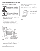
must be fully enclosed on the top, sides and back. • The dishwasher must not support any part of the enclosure. Countertop Dishwasher Clearances: In a corner installation, provide at least 2" clearance between the dishwasher and the adjacent cabinet, wall, or other appliance. Provide at least 28 - GE PDWT400RBB | Installation Instructions - Page 4
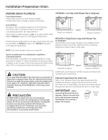
or 32" minimum, high drain loop will result in improper draining of the dishwasher, which may cause damage. PRECAUCIÓN SE DEBE USAR un espacio de aire si tee or disposer and the air gap according to the manufacturer's instructions. Cabinet Preparation for drain line Drill a 1-1/2" diameter hole in - GE PDWT400RBB | Installation Instructions - Page 5
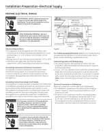
Instructions-Power Cord Models This appliance must be grounded. In the event of a malfunction or breakdown, grounding will reduce the risk of electric shock by providing a path of least resistance for electric in the back wall of the dishwasher enclosure. ADVERTENCIA La conexión incorrecta del - GE PDWT400RBB | Installation Instructions - Page 6
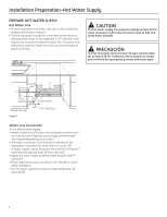
line may pass through the same hole as the electrical cable and drain hose, or an additional 1-1/2" diameter connection is on the bottom-left side of the dishwasher. Install the hot water inlet line, using 3/8" or and 150°F. • Flush water line to clean out debris. Use a bucket to catch water and debris. - GE PDWT400RBB | Installation Instructions - Page 7
in the installation package and set aside for use in the listed steps. • Trim pieces - Step 2 • Junction box • Owner's Manual - Step 19 and Step 24 • Hard Water test strip - Step 21 • Sound upgrade kit (selected models) - Step 3 - CHECK DOOR BALANCE • With dishwasher on the wood skid, check the door - GE PDWT400RBB | Installation Instructions - Page 8
this step if dishwasher will be permanently connected to the house electrical system. In this if your model does not have a sound upgrade kit. If your model does have dishwasher wire, the smooth power cord wire to the black dishwasher wire and the ground to the green dishwasher wire. Use UL-listed - GE PDWT400RBB | Installation Instructions - Page 9
hose and tighten clamp. NOTE: Drain hose supplied with dishwasher is approximately 78" long. If a longer hose is needed, a 120" long hose (10 feet) may be purchased from an authorized GE appliance dealer. The 10' long hose is part number GPF10L. Pump Outlet Hose Stops Hose Clamp Check Valve - GE PDWT400RBB | Installation Instructions - Page 10
. Insert drain hose into the hole in cabinet side. If a power cord is used, guide the end through a separate hole. Maximum Drain Hose Length 10' Insulation Blanket Water Line STEP 12 - SLIDE DISHWASHER THREEFOURTHS OF THE WAY INTO CABINET IMPORTANT - DO NOT PUSH AGAINST FRONT PANEL WITH KNEES - GE PDWT400RBB | Installation Instructions - Page 11
freely and does not contact the cabinet frame. Special Considerations for Positioning Top-Mount Control Models The controls on these models are designed to be hidden by your countertop. Align the dishwasher as shown in Figure V. Leave a 1/2" minimum gap between the underside of the countertop and - GE PDWT400RBB | Installation Instructions - Page 12
For Top-Mount Control Models: Make sure 1/2" minimum gap is maintained. • For All Models: Place level on door to check that the dishwasher is level side to 2 to secure dishwasher at the sides. 2^d]cTac^_ - GE PDWT400RBB | Installation Instructions - Page 13
properly. IMPORTANT - When connecting drain line to disposer, check to be sure that drain plug has been removed. DISHWASHER WILL NOT DRAIN IF PLUG IS LEFT IN PLACE. AT\^eT 7^__Ta ?[dV Tip: Avoid unnecessary service call charges. Always be sure disposer drain plug has been removed before attaching - GE PDWT400RBB | Installation Instructions - Page 14
list after installing your dishwasher to avoid charges for a service call that is not covered by your warranty. ■ Check to be sure power is OFF. ■ Open door and remove all foam and paper packaging. ■ Locate the Owner's Manual set aside in step 1. ■ Read the Owner's Manual for operating instructions - GE PDWT400RBB | Installation Instructions - Page 15
water hardness. Refer to the section titled "Water Hardness Calibration" in your Owner's Manual for information on how to calibrate your dishwasher. STEP 22 - INSTALL SOUND UPGRADE KIT IF EQUIPPED Skip this step if your model does not have the Sound Upgrade Kit. • Locate sound upgrade kit set aside - GE PDWT400RBB | Installation Instructions - Page 16
the floor to ensure quiet dishwasher operation. STEP 24 - LITERATURE • Be sure to leave complete literature package, Installation Instructions and product samples with the consumer. SPECIFICATIONS SUBJECT TO CHANGE WITHOUT NOTICE GE Consumer & Industrial General Electric Company Louisville, Kentucky - GE PDWT400RBB | Installation Instructions - Page 17
encastré Si vouz des questions, appelez 800.GE.CARES ou visitez notre site Web : GEAppliances.com Au Canada, appelez le 1.800.561.3344 ou visitez : www.electromenagersge.ca AVANT DE COMMENCER ASRTROÊPT Il faut lire soigneusement toutes ces instructions. IMPORTANT - Le lave-vaisselle DOIT être - GE PDWT400RBB | Installation Instructions - Page 18
Clamps ■ Ruban d'étanchéité de filetage ■ Serre-fils sur la liste UL (3) Matériaux uniquement requis en cas Coude à angle droit, bague vidange GPF10L (longueur de 3 m [10 pi]) si Strain Relief nécessaire Electrical Cable Coupler OUTILS NÉCESSAIRES : Air Gap Hose Clamps ■ Tournevis cruciforme ■ - GE PDWT400RBB | Installation Instructions - Page 19
Préparation pour l'installation - Enceinte PRÉPARATION DE L'ENCEINTE DU LAVE-VAISSELLE AVERTISSEMENT Pour réduire le risque de choc électrique, d'incendie ou de blessures, l'installateur doit s'assurer, au moment de l'installation, que le lave-vaisselle est complètement enclos. • L'ouverture de l' - GE PDWT400RBB | Installation Instructions - Page 20
Préparation pour l'installation - Vidange PRÉPARATION DE LA PLOMBERIE DE VIDANGE Exigences de vidange • Le tuyau de vidange ne peut pas être plus de 3 m (10 pi) de long. • Une boucle de vidange élevée ou un dispositif anti-siphon est requis. Voir ci-dessous. MÉTHODE 1 - Dispositif anti-siphon avec - GE PDWT400RBB | Installation Instructions - Page 21
branché à la borne de terre de l'équipement ou à un fil sur l'appareil. Instructions de mise à la terre - Modèles avec un cordon d'alimentation Cet appareil doit l'autre, de l'arrière ou du sol, dans la zone hachurée dont les dimensions sont détaillées à la figure A et qui est illustrée ci-dessus. • - GE PDWT400RBB | Installation Instructions - Page 22
Préparation pour l'installation - Alimentation d'eau chaude PRÉPARATION DE L'ALIMENTATION D'EAU CHAUDE Tuyau d'eau chaude • Le tuyau peut entrer d'un côté ou de l'autre, de l'arrière ou du sol, dans la zone hachurée montrée à la figure F. • Le tuyau peut passer dans le même trou que le câble é - GE PDWT400RBB | Installation Instructions - Page 23
Installation du lave-vaisselle PRUDENCE : Ne pas enlever la palette en bois avant d'être prêt à installer le lave-vaisselle. Le lave-vaisselle bascule lorsque la porte est ouverte sans la base. Type 1 - Câble à un trou Ajuster la tension en plaçant le crochet de ressort dans un des trois trous du - GE PDWT400RBB | Installation Instructions - Page 24
alimentation WX09X70910, en vente chez les distributeurs agréés d'appareils ménagers GE, satisfait à ces critères. Environ 3,2 mm (1/8 po) duction de bruit. • Enlever les deux vis de support de plinthe et le support de plinthe. Jeter le support et mettre les vis de côté en vue d'utilisation - GE PDWT400RBB | Installation Instructions - Page 25
le lave-vaisselle est environ 2 m de long (78 po). Si nécessaire, un tuyau de 3 m (10 pi) est disponible chez un distributeur agréé d'appareils ménagers GE. Le tuyau de 3 m (10 pi) porte le numéro de pièce GPF10L. Figure Q Conseil pour éviter les frais d'intervention inutiles. Vérifier que tous les - GE PDWT400RBB | Installation Instructions - Page 26
Installation du lave-vaisselle ÉTAPE 11 : INSERTION DU TUYAU DE VIDANGE À TRAVERS L'ARMOIRE • Mettre le lave-vaisselle en position devant l'ouverture. Insérer le tuyau de vidange dans le côté de l'armoire. Si un cordon d'alimentation est utilisé, guider son extrémité dans un trou séparé. Longueur - GE PDWT400RBB | Installation Instructions - Page 27
Installation du lave-vaisselle ÉTAPE 13 : PLACEMENT DU LAVE-VAISSELLE À SA POSITION FINALE • Pousser le lave-vaisselle tout à fait dans l'armoire. • Pousser des mains sur les côtés. Ne pas utiliser le genou pour ne pas endommager la porte. • Pendant la mise en place dans l'armoire, vérifier que la - GE PDWT400RBB | Installation Instructions - Page 28
de mise à niveau postérieur Boîte de jonction Trou d'accès droit, y accéder en desserrant la vis de support de la boîte de jonction (à travers le trou d'accès) et tourner le support dans le sens Tourner les pieds pour régler des aiguilles d'une montre. Figure Y • Le lave-vaisselle est - GE PDWT400RBB | Installation Instructions - Page 29
Installation du lave-vaisselle ÉTAPE 16 : BRANCHEMENT DE L'ALIMENTATION D'EAU Brancher le tuyau d'alimentation d'eau au coude à angle droit. • Glisser l'écrou de compression et ensuite la bague sur l'extrémité du tuyau d'eau. • Insérer le tuyau d'eau dans le coude à angle droit. • Glisser la bague - GE PDWT400RBB | Installation Instructions - Page 30
liste UL. #282#2F8re2nFcrhench 14 ÉTAPE 19 : LISTE DE VÉRIFICATION AVANT DE FAIRE LES ESSAIS Examiner cette liste rangé à l'étape 1. ■ Lire les instructions d'utilisation dans le Manuel d'utilisation. ■ Vé présente. ■ Éviter les frais de service en contrôlant qu'un dispositif anti-siphon ou un - GE PDWT400RBB | Installation Instructions - Page 31
Installation du lave-vaisselle ÉTAPE 20 : ESSAI DU LAVE-VAISSELLE AVEC DE L'EAU ■ Mettre le circuit sous tension (ou brancher le cordon d'alimentation dans la prise de courant, si installée). ■ Mettre le lave-vaisselle en marche pour vérifier qu'il n'y a pas de fuites Modèles à commandes sur le - GE PDWT400RBB | Installation Instructions - Page 32
laisser au consommateur l'enveloppe complète de documentation, les instructions d'installation et les échantillons de produit. LES DONNÉES TECHNIQUES PEUVENT CHANGER SANS PRÉAVIS GE Consumer & Industrial General Electric Company Louisville, Kentucky 40225 GEAppliances.com 206C1559P199 31-30260 07
-
 1
1 -
 2
2 -
 3
3 -
 4
4 -
 5
5 -
 6
6 -
 7
7 -
8
-
9
-
10
-
11
-
12
-
13
-
14
-
15
-
16
-
17
-
18
-
19
-
20
-
21
-
22
-
23
-
24
-
25
-
26
-
27
-
28
-
29
-
30
-
31
-
32
 |
 |

GE Consumer & Industrial
Appliances
Installation Instructions
Built-In Dishwasher
If you have questions, call 800.GE.CARES (800.432.2737) or visit our Website at: GEAppliances.com
In Canada call 1.800.561.3344 or www.GEAppliances.ca
imagination at work
IMPORTANT
– The dishwasher MUST
be installed to allow for future removal from the enclosure
if service is required.
If you received a damaged dishwasher, you should
immediately contact your dealer or builder.
Optional Accessories – See the Owner’s Manual for available
custom panel kits.
FOR YOUR SAFETY
Read and observe all CAUTIONS and WARNINGS
shown throughout these instructions. While performing
installations described in this booklet, gloves and either
safety glasses or goggles should be worn.
READ CAREFULLY.
KEEP THESE INSTRUCTIONS.
Stainless Steel Tub Models
IMPORTANT
– Observe all governing codes and
ordinances.
•
Note to Installer
– Be sure to leave these instructions for the
consumer’s and local inspector’s use.
•
Note to Consumer
– Keep these instructions with your
Owner’s Manual for future reference.
•
Skill Level
– Installation of this dishwasher requires
basic mechanical, electrical and plumbing skills.
Proper
installation is the responsibility of the installer. Product
failure due to improper installation is not covered under
the GE Appliance Warranty. See warranty information.
•
Completion Time – 1 to 3 Hours
. New installations require
more time than replacement installations.
BEFORE YOU BEGIN
Read these instructions completely and
carefully.
STOP