Gigabyte G250-G52 Manual
Gigabyte G250-G52 Manual
 |
View all Gigabyte G250-G52 manuals
Add to My Manuals
Save this manual to your list of manuals |
Gigabyte G250-G52 manual content summary:
- Gigabyte G250-G52 | Manual - Page 1
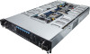
G250-S88 Dual LGA2011 sockets R3 motherboard for Intel® E5-2600 V3 series processors Service Guide Rev. 1.0 - Gigabyte G250-G52 | Manual - Page 2
to assist in the use of this product, GIGABYTE provides the following types of documentations: For detailed product information, carefully read the User's Manual. For more information, visit our website at: http://b2b.gigabyte.com You are a professional? Get an access to our complete source of - Gigabyte G250-G52 | Manual - Page 3
Preface Before using this information and the product it supports, please read the following general information. 1. This Service Guide provides you with all technical information relating to the BASIC CON- FIGURATION decided for GIGABYTE's "global" product offering. To better fit local - Gigabyte G250-G52 | Manual - Page 4
Table of Contents Box Contents...7 Safety, Care and Regulatory Information 8 Chapter 1 Hardware Installation 11 1-1 Installation Precautions 11 1-2 Product Specifications 12 1-3 System Block Diagram 14 Chapter 2 System Hardware Installation 15 2-1 Removing Chassis Cover 16 2-2 Removing and - Gigabyte G250-G52 | Manual - Page 5
5-1 The Main Menu 51 5-2 Advanced Menu 54 5-2-1 Serial Port Console Redirection 55 5-2-2 PCI Subsystem Settings 59 5-2-2-1 PCI Express Settings 61 5-2-3 Network Stack...63 5-2-4 CSM Configuration 64 5-2-5 Post Report Configuration 66 5-2-6 Trusted Computing 67 5-2-7 USB Configuration 68 - Gigabyte G250-G52 | Manual - Page 6
...124 5-7 Save & Exit Menu 126 5-8 BIOS POST Codes 128 5-9 BIOS POST Beep code 132 5-9-1 PEI Beep Codes...132 5-9-2 DEX Beep Codes 132 5-10 BIOS Recovery Instruction 133 - 6 - - Gigabyte G250-G52 | Manual - Page 7
Box Contents G250-S88 System Driver CD Heat Sink x 2 RAID Key (Optional) • The box contents above are for reference only and the actual items shall depend on the product package you obtain. The box contents are subject to change without notice. • The motherboard image is for reference only. - 7 - - Gigabyte G250-G52 | Manual - Page 8
safely when it is used in accordance with its marked electricalratings and product usage instructions • Do not use this product near water or a heat source.* Set specified in the product's documentation. • Only authorized service technicians should repair laser devices. Precaution for Product with - Gigabyte G250-G52 | Manual - Page 9
environment. This equipmentgenerates, uses, and can radiate radio frequency energy and, if not installed and used in accordance withthe instruction manual, may cause harmful interference to radio communications. Operation of thisequipment in a residential area is likely to cause harmful interference - Gigabyte G250-G52 | Manual - Page 10
please contact your local government office, your household waste disposal service or where you purchased the product for details of environmentally may contact us at the Customer Care number listed in your product's user's manual and we will be glad to help you with your effort. Battery Warning: - Gigabyte G250-G52 | Manual - Page 11
of electrostatic discharge (ESD). Prior to installation, carefully read the service guide and follow these procedures: • Prior to installation, do not remove are uncertain about any installation steps or have a problem related to the use of the product, please consult a certified computer technician. - Gigabyte G250-G52 | Manual - Page 12
MEZZ_1/Proprietary slot) ŠŠ 1 x PCI Express x8 slot, running at x8 (Gen3/MEZZ_2/Proprietary slot) ŠŠ ASPEED® AST2400 supports 16MB DDR3 VRAM ŠŠ 8 x 2.5" Hot-Swap SATA HDDs ŠŠ Support for Intel IRSTe SATA RAID 0, RAID 1, RAID 5, RAID 10 System Fans USB Internal Connectors ŠŠ 8 x 80x80x38mm 15000rpm - Gigabyte G250-G52 | Manual - Page 13
Rear Panel I/O Front Panel LED/Buttons I/O Controller Hardware Monitor BIOS Environment Ambient Temperature ŠŠ 2 x USB 2.0/3.0 ports ŠŠ 2 x 10G SFP+ LAN ports ŠŠ 1 x 10/100/1000 dedicated management LAN port ŠŠ 1 x Serial port ŠŠ 1 x VGA port ŠŠ 1 x Power switch button ŠŠ 1 x ID switch button ŠŠ 1 - Gigabyte G250-G52 | Manual - Page 14
1-3 System Block Diagram Hardware Installation - 14 - - Gigabyte G250-G52 | Manual - Page 15
Chapter 2 System Hardware Installation Pre-installation Instructions Perform the steps below before you open the server or before you remove or replaceany component. • Back up all important system and data files before - Gigabyte G250-G52 | Manual - Page 16
Chassis Cover Before you remove or install the system cover • Make sure the system is not turned on or connected to AC power. Follow these instructions to remove the system cover: 1. Loosen and remove the screws securing the top cover. 2. Slide the back cover toward the rear of the chassis to - Gigabyte G250-G52 | Manual - Page 17
2-2 Removing and Installing the Fan Duct Follow these instructions to remove/install the fan duct: 1. Lift up to remove the fan duct 2. To install the fan duct, align the fan duct with the guiding groove. Push down the fan duct into chassis until its firmly seats - 17 - Hardware Installation - Gigabyte G250-G52 | Manual - Page 18
you begin to install the CPU: • Make sure that the motherboard supports the CPU. • Always turn off the computer and unplug the power cord described in the following sections unless you are a qualified service technician. Follow these instructions to install the CPU: 1. Release then lift up the - Gigabyte G250-G52 | Manual - Page 19
2-4 Installing the Heat Sink Follow these instructions to install the heat sinks: 1. Apply thermal compound evenly on the top of the CPU. 2. Remove the protective cover from the underside of the heat - Gigabyte G250-G52 | Manual - Page 20
CPU0 P/N: 25ST1-523200-C1R CPU1 P/N: 25ST1-443101-T4R Hardware Installation - 20 - - Gigabyte G250-G52 | Manual - Page 21
insert the memory, switch the direction. 2-5-1 Triple Channel Memory Configuration The system provides 24 DDR4 memory sockets for per CPU and supports Triple Channel Technology. When the memory is installed, the BIOS will automatically detect the specifications and capacity of the memory. Enabling - Gigabyte G250-G52 | Manual - Page 22
the power cord from the power outlet to prevent damage to the memory module. Be sure to install DDR3 DIMMs on this motherboard. Follow these instructions to install the Memory: 1. Insert the DIMM memory module vertically into the DIMM slot, and push it down. 2. Close the plastic clip at both edges - Gigabyte G250-G52 | Manual - Page 23
installing a PCI card. Failure to observe these warnings could result in personal injury or damage to equipment. For GPU0/GPU1/GPU6/GPU7 Follow these instructions to install PCI Expansion card: 1. Loosen and remove the screws securing the PCI cage. 2. Pull the two plastic handles to lift up the PCI - Gigabyte G250-G52 | Manual - Page 24
4 3 2 x 3 Power cable 2 x 4 Power cable For Slot 1 PCIE_1 (Slot 1) 2 x 3 Power cable 2 x 4 Power cable For Slot 2 PCIE_2 (Slot 2) • If the GPGPU card supports 225W, connect 2 x 4 power cable. • If the GPGPU card supports 300W, connect 2 x 4 and 2 x 3 power cables. - 24 - Hardware Installation - Gigabyte G250-G52 | Manual - Page 25
For GPU2/GPU3/GPU4/GPU5 Follow these instructions to install PCI Expansion card: 1. Loosen and remove the screws securing the PCI cage. 2. Pull the two plastic handles to lift up the PCI cage - Gigabyte G250-G52 | Manual - Page 26
1 2 4 3 Hardware Installation - 26 - - Gigabyte G250-G52 | Manual - Page 27
For Slot 1 • Please insert the PCI cage into the selected slot with the correct orientation. See illustrated below for instruction. • If the GPGPU card supports 225W, connect 2 x 4 power cable. • If the GPGPU card supports 300W, connect 2 x 4 and 2 x 3 power cables. Hardware Installation - 27 - - Gigabyte G250-G52 | Manual - Page 28
the server prior to installing a PCI card. Failure to observe these warnings could result in personal injury or damage to equipment. Follow these instructions to install Add-on card: 1. Remove the rear bracket. 2. Secure the stand-off on the motherboard with screws. 3. Attach the interposer card to - Gigabyte G250-G52 | Manual - Page 29
from the server prior to installing a PCI card. Failure to observe these warnings could result in personal injury or damage to equipment. Follow these instructions to install Add-on card: 1. Remove the rear bracket. 2. Attach the mylar in the direction of the arrow. 3. Insert the gasket in the - Gigabyte G250-G52 | Manual - Page 30
3 7 5 6 4 Hardware Installation - 30 - - Gigabyte G250-G52 | Manual - Page 31
not fit back into the bay if inserted incorrectly. • Make sure that the HDD is connected to the HDD connector on the backplane. Follow these instructions to install the Hard disk drive: 1. Press the release button. 2. Pull the locking lever to remove the HDD tray. 3. Slide hard disk into blank - Gigabyte G250-G52 | Manual - Page 32
2-8 Replacing the FAN Assemblly CAUTION! Before you remove or install the system fan cage, take the steps: • Make sure the system is not turned on or connected to the AC power. • Disconnect all necessary cable connections. Failure to observe these warnings could result in personal injury or damage - Gigabyte G250-G52 | Manual - Page 33
Airflow direction 3 Hardware Installation - 33 - - Gigabyte G250-G52 | Manual - Page 34
For SYS_FAN1/SYS_FAN2 Follow these instructions to replace the fan assembly: 1. Disconnect fan cable. Lift up the fan assembly from the chassis. 2. Attach the four rubbers on the system fan. 3. Reverse - Gigabyte G250-G52 | Manual - Page 35
For GPU12E_FAN/GPU56E_FAN (Smart Fan) Follow these instructions to replace the fan assembly: 1. Loosen and remove the screws securing the fan cage. 2. Remove the fan cage out of the system. 3. Loosen and remove - Gigabyte G250-G52 | Manual - Page 36
CAUTION! • To avoid fan cable damages, please make sure the fan cables are firmly seated in the groove. - 36 - Hardware Installation - Gigabyte G250-G52 | Manual - Page 37
to reduce the risk of injury from electric shock, disconnect AC power from the power supply before removing it from the system. Follow these instructions to replace the power supply: 1. Disconnect all power cables. 2. Pull up the power supply handle and press the retaining clip on the right side - Gigabyte G250-G52 | Manual - Page 38
Chapter 3 System Appearance 3-1 Front View No. Decription 1. Front panel LED and buttons 2. System fan (GPU78_FAN) 3. 2.5-inch hard disk drive #1 4. 2.5-inch hard disk drive #2 5. 2.5-inch hard disk drive #3 6. 2.5-inch hard disk drive #4 7. 2.5-inch hard disk drive #5 8. 2.5-inch hard disk drive #6 - Gigabyte G250-G52 | Manual - Page 39
3-2 Rear View 1 2 7 56 8 1112 4 9 10 3 13 14 14 15 No. Decription 1. System fan (GPU12E_FAN) 2. VGA port 3. Serial port 4. Power button/LED 5. ID switch button 6. Reset button (top)/NMI button (buttom) 7. System status LED 8. LAN1 Active/Link (top)/Speed (buttom)LEDs 9. Dual 10G SFP+ - Gigabyte G250-G52 | Manual - Page 40
3-3 Front Panel LED and Buttons 3 4 1 5 2 6 7 No. Name 1. Power button and LED 2. ID Button and LED 3. LAN1 Activity LED 4. LAN2 Activity LED 5. HDD Activity LED 6. System Status LED Color Green Green N/A Blue N/A Green Green N/A Green Green N/A Green Green/ AMber Green Green - Gigabyte G250-G52 | Manual - Page 41
3-4 Rear System Button and LEDs 1 2 356 7 No. Name Power button 1. and LED 2. ID Button and LED 3. Reset Button 4. NMI button 5. System Status LED 6. LAN1 Active/ Link LED 7. LAN2 Active/ Link LED Color Green Green N/A Blue N/A Green Amber N/A Green N/A Green N/A 4 Status Solid On - Gigabyte G250-G52 | Manual - Page 42
3-5 Hard Disk Drive LEDs LED RAID No RAID configuration (via HBA, PCH) Disk LED (LED on Back Panel) Removed HDD Slot (LED on Back Panel) RAID configuration (via HW RAID Card or SW RAID Card) Disk LED Removed HDD Slot (Back Panel) Color Green Amber Green Amber Green Amber Green Amber Locate On - Gigabyte G250-G52 | Manual - Page 43
3-6 Hard Disk Back Plane Board Jumper Setting B_SEL BPB_CN_2 A_SEL SAS_4-7 BPB_CN_2 SAS_0-3 BPB_PWR 1-2Close 2-3 Close A_SEL SATA_HDD SAS_HDD B_SEL SATA_HDD SAS_HDD Hardware Installation - 43 - - Gigabyte G250-G52 | Manual - Page 44
3-7 Cable Routing 9 6 5 4 2 9 1 8 99 99 99 2 11 99 78 3 10 10 3 78 5 9 6 9 4 No. Suggest Cable No. Suggest Cable 1. System main power cable 2. CPU 0 12V power cable 3. CPU 1 12V power cable 4. Front panel cable 5. Mini SAS cable #1 6. Mini SAS cable #2 7. HDD back - Gigabyte G250-G52 | Manual - Page 45
Chapter 4 Motherboard Components 4-1 MG50-G20 Motherboard Components 59 71 69 67 65 63 62 61 60 72 70 68 66 64 1 2 5 6 79 10 11 12 13 14 3 4 8 15 73 21 17 20 16 18 19 223 52 53 54 55 56 57 58 29 28 27 26 25 24 23 31 45 44 51 43 50 49 42 48 47 41 46 40 30 32 33 34 35 39 36 - Gigabyte G250-G52 | Manual - Page 46
26 DIMM_P0_B0 27 DIMM_P0_B1 28 DIMM_P0_B2 29 CPU0 30 CPU1 31 PCIE_3 32 DIMM_P1_H2 33 DIMM_P1_H1 34 DIMM_P1_H0 35 DIMM_P1_G2 36 DIMM_P1_G1 37 DIMM_P1_G0 38 PCIE_4 39 BP_1 40 ATX2_2 41 ATX2_1 42 ATX2_3 43 FP_2 44 PMBUS_SEL 45 PCIE_2 46 DIMM_P1_F2 47 DIMM_P1_F1 48 DIMM_P1_F0 49 DIMM_P1_E2 50 DIMM_P1_E1 - Gigabyte G250-G52 | Manual - Page 47
70 ME_UPDATE 71 CASE_OPEN 72 MEZZ_1 73 LED_BMC ME update jumper Chassis intrusion header Mezzine slot 1 (x16 slot/Proprietary/Running at x8) BMC firmware readiness LED On: BMC frmware is initial Blinking: BMC frmware is ready Off: System is powered off - 47 - Hardware Installation - Gigabyte G250-G52 | Manual - Page 48
4-2 Jumper Setting 8 64 9 753 2 1 No. Jumper Code PMBUS_SEL 1. (PMBus Power Select Jumper) Jumper Setting 1-2 Close: PMBus connects to PCH. 2-3 Close: PMBus connects to BMC. (Default setting) 2. CLR_CMOS 1-2 Close: Normal operation (Default setting) (Clearing CMOS Jumper) 2-3 Close: - Gigabyte G250-G52 | Manual - Page 49
Setup program, press the key during the POST when the power is turned on. • BIOS flashing is potentially risky, if you do not encounter problems of using the current BIOS version, it is recommended that you don't flash the BIOS. To flash the BIOS, do it with caution. Inadequate BIOS - Gigabyte G250-G52 | Manual - Page 50
Main This setup page includes all the items in standard compatible BIOS. Advanced This setup page includes all the items of AMI BIOS special enhanced features. (ex: Auto detect fan and temperature status, automatically configure hard disk parameters.) Intel RC Setup This setup page includes - Gigabyte G250-G52 | Manual - Page 51
5-1 The Main Menu Once you enter the BIOS Setup program, the Main Menu (as shown below) appears on the screen. Use arrow keys to move among the items and press to accept or enter other sub-menu. Main Menu Help The on-screen description of a highlighted setup option is displayed on the bottom - Gigabyte G250-G52 | Manual - Page 52
BIOS Information Porject Name Display the project name information. Porject Version Display version number of the BIOS setup utility. BIOS Build Date and Time Displays the date and time when the BIOS setup utility was created. BMC Information BMC Firmware Version Display version number of the - Gigabyte G250-G52 | Manual - Page 53
Onboard LAN Information LAN1/LAN2 MAC Address Display LAN1/LAN2 MAC address information. System Date Set the date following the weekday-month-day- year format. System Time Set the system time following the hour-minute- second format. - 53 - BIOS Setup - Gigabyte G250-G52 | Manual - Page 54
5-2 Advanced Menu The Advanced menu display submenu options for configuring the function of various hardware components. Select a submenu item, then press Enter to access the related submenu screen. BIOS Setup - 54 - - Gigabyte G250-G52 | Manual - Page 55
5-2-1 Serial Port Console Redirection - 55 - BIOS Setup - Gigabyte G250-G52 | Manual - Page 56
BIOS Setup - 56 - - Gigabyte G250-G52 | Manual - Page 57
with slow devices may require more than 1 stop bit. Options available: 1/2. Default setting is 1. VT-UTF8 Combo Key Support (Note) Enable/Disable VT-UTF8 Combo Key Support. Options available: Enabled/Disabled. Default setting is Enabled. Recorder Mode (Note) When this mode enabled, only text will - Gigabyte G250-G52 | Manual - Page 58
Note) On Legacy OS, the number of Rows and Columns supported redirection. Options available: 80x24/80X25. Default setting is 80x24. setting is Always Enable. Out-of-Bnad Mgmt Port Microsoft Windows Emerency Management Service (EMS) allows for remote management of a Windows Server OS through a serial - Gigabyte G250-G52 | Manual - Page 59
5-2-2 PCI Subsystem Settings PCI Express Slot #1-1/#1-2/#2-1/#2-2/#3-1/#3-2/#4-1/#4-2/#5/#6 I/O ROM When enabled, This setting will initialize the device expansion ROM for the related PCI-E slot. Options available: Enabled/Disabled. Default setting is Enabled. Onboard LAN#1/#2 Controller Enable/ - Gigabyte G250-G52 | Manual - Page 60
SR-IOV Support If system has SR-IOV capable PCIe Devices, this option enables or disables Single Root IO Virtualization Support. Options available: Enabled/Disabled. Default setting is Disabled. PCI Express Settings Press [Enter] for configuration of advanced items. BIOS Setup - 60 - - Gigabyte G250-G52 | Manual - Page 61
5-2-2-1 PCI Express Settings PCI Express Device Register Settings Relaxed Ordering Enable/DIsable PCI Express Device Relaxed Ordering feature. Options available: Enabled/Disabled. Default setting is Disabled. Extended Tag Wnen this feature is enabled, the system will allow device to use 8-bit Tag - Gigabyte G250-G52 | Manual - Page 62
Link Training Timeout (us) Define the number of Microseconds software will wait before polling 'Link Training' bit in Link Status register. Press / keys to increase or decrease the desired values. Value rang is from 10 to 10000 us. Unpopulated Links When this item is set to 'Disable Link, - Gigabyte G250-G52 | Manual - Page 63
(Note) Enable/Disable Ipv4 PXE feature. Options available: Enabled/DIsabled. Default setting is Enabled. Ipv6 PXE Support(Note) Enable/Disable Ipv6 PXE feature. Options available: Enabled/DIsabled. Default setting is Enabled. PXE boot wait time(Note) Press / keys to increase or decrease - Gigabyte G250-G52 | Manual - Page 64
Support Module Configuration CSM Support Enable/Disable Compatibility Support Module (CSM) support. Options available: Enabled/Disabled. Default setting is Enabled. CSM16 Module Version Display CSM Module version information. Gate20 Active Upon Request: GA20 can be disabled using BIOS services - Gigabyte G250-G52 | Manual - Page 65
Option ROM execution Network Controls the execution UEFI and Legacy PXE OpROM. Options available: Do not launch/UEFI/Legacy. Default setting is Legacy. Storage Controls the execution UEFI and Legacy Storage OpROM. Options available: Do not launch/UEFI/Legacy. Default setting is Legacy. Video - Gigabyte G250-G52 | Manual - Page 66
5-2-5 Post Report Configuration Post Report Configuration Error Message Report Post Error Message Enable/Disable Info Error Message support. Options available: Enabled/Disabled. Default setting is Enabled. BIOS Setup - 66 - - Gigabyte G250-G52 | Manual - Page 67
5-2-6 Trusted Computing Configuration Security Device Support Select Enabled to activate TPM support feature. Options available: Enabled/Disabled. Default setting is Disabled. Current Status Information Display current TPM status information. - 67 - BIOS Setup - Gigabyte G250-G52 | Manual - Page 68
USB Configuration USB Devices: Display the USB devices connected to the system. XHCI Hand-off Enable/Disable XHCI (USB 3.0) Hand-off support. Options available: Enabled/Disabled. Default setting is Enabled. EHCI Hand-off Enable/Disable EHCI (USB 2.0) Hand-off function. Options available: Enabled - Gigabyte G250-G52 | Manual - Page 69
5-2-8 Chipset Configuration Restore on AC Power Loss (Note) Defines the power state to resume to after a system shutdown that is due to an interruption in AC power. When set to Last State, the system will return to the active power state prior to shutdown. When set to Stay Off, the system remains - Gigabyte G250-G52 | Manual - Page 70
5-9 SIO Configuration BIOS Setup - 70 - - Gigabyte G250-G52 | Manual - Page 71
AMI SIO Driver Version Display the AMI SIO driver version information. Super IO Chip Logical Device(s) Configuration [*Active*] Serial Port 1/2 Press [Enter] for confuguration of advanced items. Serial Port 1 Configuration Use This Device When enabled allows you to configure the serial port 1 - Gigabyte G250-G52 | Manual - Page 72
IO=3F8h; IRQ=4; DMA;/ IO=3F8h; IRQ=3,4,5,7,9,10,11,12; DMA;/ IO=2F8h; IRQ=3,4,5,7,9,10,11,12; DMA;/ IO=3E8h; IRQ=3,4,5,7,9,10,11,12; DMA;/ IO=2E8h; IRQ=3,4,5,7,9,10,11,12; DMA;. Default setting is Use Automatic Settings. Serial Port 2 Configuration Use This Device When enabled allows you to - Gigabyte G250-G52 | Manual - Page 73
5-2-10 iSCSI Configuration iSCSI Initiator Name Add an Attempts Press [Enter] for configuration of advanced items. Delete Attempts Press [Enter] for configuration of advanced items. Change Attempt Order Press [Enter] for configuration of advanced items. - 73 - BIOS Setup - Gigabyte G250-G52 | Manual - Page 74
5-3 Intel RC Setup Menu Intel RC Setup menu displays submenu options for configuring the function of North Bridge and South Bridge. Select a submenu item, then press Enter to access the related submenu screen. RC Revision Display Intel RC version information. BIOS Setup - 74 - - Gigabyte G250-G52 | Manual - Page 75
5-3-1 Processor Configuration - 75 - BIOS Setup - Gigabyte G250-G52 | Manual - Page 76
Disabled. Default setting is Enabled. Enable SMX (Intel Safer Mode Extensions Technology) Enable/Disblae Intel Safer Mode Extensions (SMX) support function. Options available: Enabled/Disabled. Default setting is Disabled. Hardware Prefetcher Select whether to enable the speculative prefetch unit of - Gigabyte G250-G52 | Manual - Page 77
/112. Default setting is 32. X2APIC Options available: Enabled/Disabled. Default setting is Disabled. AES-NI Enable/Disable AES-NI (Intel Advanced Encryption Standard New Instructions) support function. Options available: Enabled/Disabled. Default setting is Enabled. - 77 - BIOS Setup - Gigabyte G250-G52 | Manual - Page 78
5-3-1-1 Pre-Socket Configuration BIOS Setup - 78 - - Gigabyte G250-G52 | Manual - Page 79
CPU Socket 0/1 Configuration Press [Enter] for configuration of advanced items. Cores Enabled (for CPU socket 0/1) Number of Cores to enable. 0 means all cores. 14 Cores is available. Press the numeric keys to adjust desired values. - 79 - BIOS Setup - Gigabyte G250-G52 | Manual - Page 80
5-3-2 Advanced Power Management Configuration Advanced Power Management Configuration Power Technology Option available:Disable/Energy Efficient/Custom. Default setting is Custom. Config TDP Options available: Enabled/Disabled. Default setting is Enabled. Config TDP Level Options available: Nominal - Gigabyte G250-G52 | Manual - Page 81
5-3-2-1 CPU P State Control EIST (P-State) Conventional Intel SpeedStep Technology switches both voltage and frequency in tandem between high and low levels in response to processor load. Options available: Enabled/Disabled. Default setting is Enabled. Turbo Mode When this item is enabled, tje - Gigabyte G250-G52 | Manual - Page 82
5-3-2-2 CPU C State Control Package C State Limit Configure state for the C-State package limit. Options available: C0/C1 state/C2 state/C6(non Retention) state/C6(Retention) state. Default setting is C6(non Retention) state. CPU C3/C6 Report Allows you to determine whether to let the CPU enter C3/ - Gigabyte G250-G52 | Manual - Page 83
5-3-2-3 CPU T State Control ACPI T-States Enable/Disable CPU throttling by OS. Thorttling reduces power comsumption. Options available: Enabled/Disabled. Default setting is Enabled. - 83 - BIOS Setup - Gigabyte G250-G52 | Manual - Page 84
5-3-3 Common RefCode Configuration Common RefCode Configuration Isoc Mode Options available: Enabled/Disabled. Default setting is Disabled. Numa (Non-Uniform Memory Access) Options available: Enabled/Disabled. Default setting is Enabled. BIOS Setup - 84 - - Gigabyte G250-G52 | Manual - Page 85
5-3-4 QPI Configuration - 85 - BIOS Setup - Gigabyte G250-G52 | Manual - Page 86
QPI General Configuration Press [Enter] for configuration of advanced items. QPI Status Press [Enter] to view QPI status. Link Speed Mode Options available: Slow/Fast. Default setting is Fast. Link Frequency Select Options available: 6.4GB/s/8.0GB/s/9.6GB/s/Auto/Auto Limited. Default setting is Auto - Gigabyte G250-G52 | Manual - Page 87
Enabled. Memory Frequency Configure memory frequency. Options available: Auto/1333/1400/1600/1800/1867/2000/2133. Default setting is Auto. ECC Support Options available: Auto/Disabled/Enabled. Default setting is Auto. Rank Margin Tool Options available: Auto/Disabled/Enabled. Default setting is Auto - Gigabyte G250-G52 | Manual - Page 88
Memory RAS Configuration Press [Enter] for configuration of advanced items. BIOS Setup - 88 - - Gigabyte G250-G52 | Manual - Page 89
5-3-5-1 Memory Topology - 89 - BIOS Setup - Gigabyte G250-G52 | Manual - Page 90
5-3-5-2 Memory Thermal Set Throttling Configure Thermal Throttling Mode. Select OLTT or CLTT mode. Options available: Disabled/OLTT/CLTT. Default setting is CLTT. MEMHOT Throttling Mode Options available: Disabled/Output-only/Input-only. Default setting is Input-only. BIOS Setup - 90 - - Gigabyte G250-G52 | Manual - Page 91
5-3-5-3 Memory Map Socket Interleave Below 4GB Splits the 0-4GB address space between two sockets, so that both sockets get a chunk of local memory below 4GB. Options available: Disabled/Enabled. Default setting is Disabled. Channel Interleaving Options available: Auto/1-way Interleave/2-way - Gigabyte G250-G52 | Manual - Page 92
5-3-5-4 Memory RAS Configuration RAS Mode Enable/Disable RAS modes. Enabling Sparing and Mirroring is not supported. When this item is set to enabled, Sparing will be selected. Options available: Disable/Mirror/Lockstep Mode. Default setting is Disabled. Lockstep x4 DIMMs Options - Gigabyte G250-G52 | Manual - Page 93
5-3-6 IIO Configuration IIO Configuration EV DFX Features Set this option to allow DFX Lock Bits to remain clear. Options available: Enabled/Disabled. Default setting is Disabled. IOAT Configuration Press [Enter] for configuration of advanced items. Intel VT for Directed I/O (VT-d) Press [Enter] - Gigabyte G250-G52 | Manual - Page 94
5-3-6-1 IOAT Configuration IOAT Configuration Enable IOAT Control to enable/disable IOAT (Intel I/O Acceleration Technology) device. Options available: Enabled/Disabled. Default setting is Disabled. No Snoop Enable/Disable PCI Express Device No Snoop option. Options available: Enabled/Disabled. - Gigabyte G250-G52 | Manual - Page 95
optimizations. Options available: Enabled/Disabled. Default setting is Disabled. Intel VT for Directed I/O (VT-d) Enable/Disable Intel VT for Directed I/O (VT-d) support function. Options available: Enabled/Disabled. Default setting is Enabled. Interrupt Remapping Enable/Disable interrupt remapping - Gigabyte G250-G52 | Manual - Page 96
5-3-7 PCH Configuration PCH Configuration PCH Devices Press [Enter] for configuration of advanced items. PCH SATA Configuration Press [Enter] for configuration of advanced items. USB Configuration Press [Enter] for configuration of advanced items. BIOS Setup - 96 - - Gigabyte G250-G52 | Manual - Page 97
5-3-7-1 PCH Devices PCH CRID Enable/Disable Intel Compatible Revision ID. Options available: Enabled/Disabled. Default setting is Disabled. - 97 - BIOS Setup - Gigabyte G250-G52 | Manual - Page 98
5-3-7-2 PCH sSATA Configuration BIOS Setup - 98 - - Gigabyte G250-G52 | Manual - Page 99
SATA RSTe Boot Information. Options available: Enabled/Disabled. Default setting is Enabled. SATA Mode options(Note 2) Press [Enter] for configuration of advanced items. (Note 1) Only Supported When HDD is in RAID Mode. (Note 2) Only Supported When HDD is in AHCI or RAID Mode. - 99 - BIOS Setup - Gigabyte G250-G52 | Manual - Page 100
Note) Enable/Disable HDD Hot-Plug function. Options available: Enabled/Disabled. Default setting is Disabled. Configured as eSATA(Note) Display Hot-Plug supported information. Spin Up Device (for Port 0/1/2/3)(Note) On an edge detect from 0 to 1, the PCH starts a COM reset initialization to the - Gigabyte G250-G52 | Manual - Page 101
5-3-7-2-1 SATA Mode Options When SATA Type is set to IDE/AHCI Mode SATA LED locate When this option is enabled, LED/SGPIO hardware is attached. Options available: Enabled/Disabled. Default setting is Enabled. - 101 - BIOS Setup - Gigabyte G250-G52 | Manual - Page 102
banner Options available: Enabled/Disabled. Default setting is Enabled. Smart Response Technology Enable/Disable Intel Smart Response Technology support function. Options available: Enabled/Disabled. Default setting is Enabled. RAID OROM prompt delay Options available: 2 Seconds/4 Seconds/6 Seconds - Gigabyte G250-G52 | Manual - Page 103
5-3-7-3 PCH SATA Configuration BIOS Setup - 103 - - Gigabyte G250-G52 | Manual - Page 104
. Default setting is Disabled. SATA RSTe Boot Info(Note 1) Enable/Disable SATA RSTe Boot Information. Options available: Enabled/Disabled. Default setting is Enabled. (Note 1) Only Supported When HDD is in RAID Mode. (Note 2) Only Supported When HDD is in AHCI or RAID Mode. BIOS Setup - 104 - - Gigabyte G250-G52 | Manual - Page 105
Note) Enable/Disable HDD Hot-Plug function. Options available: Enabled/Disabled. Default setting is Disabled. Configured as eSATA(Note) Display Hot-Plug supported information. Spin Up Device (for Port 0/1/2/3/4/5)(Note) On an edge detect from 0 to 1, the PCH starts a COM reset initialization to the - Gigabyte G250-G52 | Manual - Page 106
5-3-7-3-1 SATA Mode Options When SATA Type is set to IDE/AHCI Mode SATA LED locate When this option is enabled, LED/SGPIO hardware is attached. Options available: Enabled/Disabled. Default setting is Enabled. - 106 - BIOS Setup - Gigabyte G250-G52 | Manual - Page 107
banner Options available: Enabled/Disabled. Default setting is Enabled. Smart Response Technology Enable/Disable Intel Smart Response Technology support function. Options available: Enabled/Disabled. Default setting is Enabled. RAID OROM prompt delay Options available: 2 Seconds/4 Seconds/6 Seconds - Gigabyte G250-G52 | Manual - Page 108
work on USB host conteoller and root ports for faster enumeration. Options available: Enabled/Disabled. Default setting is Disabled. xHCI Mode Enable/Disable xHCI (USB 3.0) support function. Options available: Smart Auto/Enabled/Disabled. Default setting is Smart Auto. - 108 - BIOS Setup - Gigabyte G250-G52 | Manual - Page 109
5-3-8 Miscellaneous Configuration Miscellaneous Configuration Active Video Select active Video type. Options available: Onboard Device/Offboard Device. Default setting is Offboard Device. BIOS Setup - 109 - - Gigabyte G250-G52 | Manual - Page 110
5-3-9 Server ME Configuration Greneral ME Configuration Operational Firmware Version Display Operational Firmware Version information. Recovery Firmware Version Display Recovery Firmware Version information. ME Firmware Features Display ME Firmware features information. ME Firmware Status #1/#2 - Gigabyte G250-G52 | Manual - Page 111
System Errors Enable/Disable system error logging function. Options available: Enabled/Disabled. Default setting is Enabled. S/W Error Injection Support Enable/Disable software injection error logging function. Options available: Enabled/Disabled. Default setting is Enabled. Whea Settings Press - Gigabyte G250-G52 | Manual - Page 112
5-3-10-1 Whea Setting WHEA Support (Windows Hardware Error Architecture) Enable/Disable WHEA Support. Options available: Enabled/Disabled. Default setting is Enabled. - 112 - BIOS Setup - Gigabyte G250-G52 | Manual - Page 113
5-3-10-2 Memory Error Enabling Memory Error Enabling Un-Correctable Errors disable Memory Options available: Enabled/Disabled. Default setting is Disabled. Memory corrected Errors enabling Options available: Enabled/Disabled. Default setting is Disabled. BIOS Setup - 113 - - Gigabyte G250-G52 | Manual - Page 114
5-3-10-3 PCI/PCI Error Enabling PCI-Ex Error Enable Options available: Yes/No. Default setting is No. - 114 - BIOS Setup - Gigabyte G250-G52 | Manual - Page 115
5-4 Server Management Menu FRB-2 Timer Enable/Disable FRB-2 timer (POST timer). Options available: Enabled/Disabled. Default setting is Disabled. FRB2 Timer timeout Configure the FRB2 Timer timeout. Options available: 3 minutes/4 minutes/5 minutes/6 minutes. Default setting is 6 minutes. Please - Gigabyte G250-G52 | Manual - Page 116
System Event Log Press [Enter] for configuration of advanced items. View FRU Information Press [Enter] to view the advanced items. BMC network configuration Press [Enter] for configuration of advanced items. - 116 - BIOS Setup - Gigabyte G250-G52 | Manual - Page 117
5-4-1 System Event Log Enabling/Disabling Options SEL Components Change this to enable or disable all features of System Event Logging during boot. Options available: Enabled/Disabled. Default setting is Enabled. Erasing Settings Erasing SEL Choose options for erasing SEL. Options available: No/Yes - Gigabyte G250-G52 | Manual - Page 118
5-4-2 View FRU Information The FRU page is a simple display page for basic system ID information, as well as System product information. Items on this window are non-configurable. - 118 - BIOS Setup - Gigabyte G250-G52 | Manual - Page 119
5-4-3 BMC network configuration BMC network configuration Select NCSI and Dedicated LAN Switch NCSI and dedicated LAN and send KCS command. Options available: Mode2(NSCI)/ Mode1 (Dedicated)/Do Nothing. Default setting is Do Nothing. Lan Channel 1 Configuration Address source Select to configure LAN - Gigabyte G250-G52 | Manual - Page 120
5-5 Security Menu The Security menu allows you to safeguard and protect the system from unauthorized use by setting up access passwords. There are two types of passwords that you can set: • Administrator Password Entering this password will allow the user to access and change all settings in the - Gigabyte G250-G52 | Manual - Page 121
automatically load the Secure Boot keys form the BIOS databases. When set to Custom, you can customize the Secure Boot settings and manually load its keys from the BIOS database. Options available: Standard/Custom. Default setting is Standard. Key Management(Note) Press [Enter] for configuration - Gigabyte G250-G52 | Manual - Page 122
5-5-1-1 Key Management Default Key Provisioning Force the system to Setup Mode. This will clear all Secure Boot Variables such as Platform Key (PK), Key-exchange Key (KEK), Authorized Signature Database (db), and Forbidden Signaures Database (dbx). Options available: Enabled/Disabled. Default - Gigabyte G250-G52 | Manual - Page 123
Append Var to KEK Press [Enter] to load additional KEK from a storage devices for an additional db and dbx management. Authorized Signature Database (DB) Display the status of Authorized Signature Database. Delete DB Press [Enter] to delete the db from your system. Set new DB Press [Enter] to - Gigabyte G250-G52 | Manual - Page 124
5-6 Boot Menu The Boot menu allows you to set the drive priority during system boot-up. BIOS setup will display an error message if the legacy drive(s) specified is not bootable. Boot Configuration Setup Prompt Timeout Number of seconds to wait for setup activation key. 65535(0xFFFF) means - Gigabyte G250-G52 | Manual - Page 125
Hard Drive BBS Priorities Press Enter to configure the boot priority. BIOS Setup - 125 - - Gigabyte G250-G52 | Manual - Page 126
5-7 Save & Exit Menu The Exit menu displays the various options to quit from the BIOS setup. Highlight any of the exit options then press Enter. Save Changes and Exit Saves changes made and close the BIOS setup. Options available: Yes/No. Discard Changes and Exit Discards changes made and exit the - Gigabyte G250-G52 | Manual - Page 127
Boot Override Press Enter to configure the device as the boot-up drive. UEFI: Built-in in EFI Shell Press on this item to Launch EFI Shell from filesystem device. - 127 - BIOS Setup - Gigabyte G250-G52 | Manual - Page 128
5-8 BIOS POST Codes PEI_CORE_STARTED 0x10 PEI_CAR_CPU_INIT 0x11 // reserved for CPU 0x12 - 0x14 PEI_CAR_NB_INIT 0x15 // reserved for NB 0x16 - 0x18 PEI_CAR_SB_INIT 0x19 // reserved for SB 0x1A - 0x1C PEI_MEMORY_SPD_READ 0x1D PEI_MEMORY_PRESENCE_DETECT 0x1E PEI_MEMORY_TIMING 0x1F - Gigabyte G250-G52 | Manual - Page 129
DXE_CPU_INIT //reserved for CPU 0x64 - 0x67 DXE_NB_HB_INIT DXE_NB_INIT DXE_NB_SMM_INIT //reserved for NB 0x6B - 0x6F DXE_SB_INIT DXE_SB_SMM_INIT DXE_SB_DEVICES_INIT //reserved for SB 0x73 - 0x77 DXE_ACPI_INIT DXE_CSM_INIT //reserved for AMI use: 0x7A - 0x7F //reserved for OEM use: 0x80 - 0x8F - Gigabyte G250-G52 | Manual - Page 130
DXE_READY_TO_BOOT DXE_LEGACY_BOOT DXE_EXIT_BOOT_SERVICES RT_SET_VIRTUAL_ADDRESS_MAP_BEGIN RT_SET_VIRTUAL_ADDRESS_MAP_END DXE_LEGACY_OPROM_INIT DXE_RESET_SYSTEM DXE_USB_HOTPLUG DXE_PCI_BUS_HOTPLUG DXE_NVRAM_CLEANUP DXE_CONFIGURATION_RESET //reserved for AMI use: 0xB8 - 0xBF //reserved for OEM use: - Gigabyte G250-G52 | Manual - Page 131
PEI_MEMORY_S3_RESUME_FAILED PEI_S3_RESUME_PPI_NOT_FOUND PEI_S3_BOOT_SCRIPT_ERROR PEI_S3_OS_WAKE_ERROR //reserved for AMI use: 0xEC - 0xEF // DXE_STATUS_CODE DXE_CPU_ERROR DXE_NB_ERROR DXE_SB_ERROR DXE_ARCH_PROTOCOL_NOT_AVAILABLE DXE_PCI_BUS_OUT_OF_RESOURCES DXE_LEGACY_OPROM_NO_SPACE DXE_NO_CON_OUT - Gigabyte G250-G52 | Manual - Page 132
5-9 BIOS POST Beep code 5-9-1 PEI Beep Codes # of Beeps 1 1 2 3 3 4 4 7 Description Memory not Installed. Memory was installed twice (InstallPeiMemory routine in PEI Core called twice) Recovery started DXEIPL was not found DXE Core Firmware Volume was not found Recovery failed S3 Resume failed - Gigabyte G250-G52 | Manual - Page 133
becomes corrupt the boot block can be used to restore the BIOS to a working state. To restore your BIOS, please follow the instructions listed below: Recovery Instruction: 1. Change xxx.ROM to amiboot.rom. 2. Copy amiboot.rom and AFUDOS.exe to USB diskette. 3. Setting BIOS Recovery jump to enabled
-
 1
1 -
 2
2 -
 3
3 -
 4
4 -
 5
5 -
 6
6 -
 7
7 -
8
-
9
-
10
-
11
-
12
-
13
-
14
-
15
-
16
-
17
-
18
-
19
-
20
-
21
-
22
-
23
-
24
-
25
-
26
-
27
-
28
-
29
-
30
-
31
-
32
-
33
-
34
-
35
-
36
-
37
-
38
-
39
-
40
-
41
-
42
-
43
-
44
-
45
-
46
-
47
-
48
-
49
-
50
-
51
-
52
-
53
-
54
-
55
-
56
-
57
-
58
-
59
-
60
-
61
-
62
-
63
-
64
-
65
-
66
-
67
-
68
-
69
-
70
-
71
-
72
-
73
-
74
-
75
-
76
-
77
-
78
-
79
-
80
-
81
-
82
-
83
-
84
-
85
-
86
-
87
-
88
-
89
-
90
-
91
-
92
-
93
-
94
-
95
-
96
-
97
-
98
-
99
-
100
-
101
-
102
-
103
-
104
-
105
-
106
-
107
-
108
-
109
-
110
-
111
-
112
-
113
-
114
-
115
-
116
-
117
-
118
-
119
-
120
-
121
-
122
-
123
-
124
-
125
-
126
-
127
-
128
-
129
-
130
-
131
-
132
-
133
 |
 |

G250-S88
Dual LGA2011 sockets R3 motherboard for Intel
®
E5-2600 V3 series processors
Service Guide
Rev. 1.0