Gigabyte GA-4MXSV User Manual
Gigabyte GA-4MXSV Manual
 |
View all Gigabyte GA-4MXSV manuals
Add to My Manuals
Save this manual to your list of manuals |
Gigabyte GA-4MXSV manual content summary:
- Gigabyte GA-4MXSV | User Manual - Page 1
GA-4MXSV Pentium Prescott 1066 Motherboard USER'S MANUAL Pentium®Prescott Processor Motherboard Rev. 1002 12ME-4MXSV-1002 - Gigabyte GA-4MXSV | User Manual - Page 2
GA-4MXSV Motherboard Layout 7 Chapter 2 Hardware Installation Process 9 Step 1: Installing Processor and CPU Haet Sink 10 Step1-1: Installing CPU 4-2 :Connectors & Jumper Setting Introduction 17 Chapter 3 BIOS Setup 27 Main ...29 Advanced Processor Options 32 Advanced 34 Memory - Gigabyte GA-4MXSV | User Manual - Page 3
Reference 61 Block Diagram 61 Chapter 5 Driver Installation 62 A.Intel Chipset Software Installation Utilities 62 B.Intel LAN Driver Installation 64 C.Intel Host RAID Driver Installation 66 D.VGA ES1000 Driver Installation 68 E.DirectX 9.0 Driver Installation 69 Chapter 6 Appendix 70 - Gigabyte GA-4MXSV | User Manual - Page 4
English GA-4MXSV Motherboard Item Checklist The GA-4MXSV motherboard IDE (ATA100 ) cable x 1 / Floppy cable x 1 CD for motherboard driver & utility GA-4MXSV user's manual Serial ATA cable x 4 I/O Shield Kit WARNING! Computer motherboards and expansion cards contain very delicate Integrated - Gigabyte GA-4MXSV | User Manual - Page 5
1 PCI-Express x8 slot ICH7R built in SATA RAID 0,1,5, 0+1 without Linux support Supports 4 SATAII conntectors 1 IDE connector 1 Floppy port supports 2 FDD with 360K, 720K,1.2M, 1.44M and 2.88M bytes. 2 PS/2 connectors 1 Parallel port supports Normal/EPP/ECP mode 1 Serial port (COM) 4 x USB 2.0 1 VGA - Gigabyte GA-4MXSV | User Manual - Page 6
GA-4MXSV Motherboard On-Board Graphic On-Board LAN ATI ES1000 with 16Mb DDR SDRAM Dual Intel 82573V Gigabit Ethernet controllers Hardware Monitor BIOS Additional Features Winbond 83792D controller Enhanced features with CPU Vcore, 1.5V reference, VCC3 (3.3V), VCC5V, +12V, 2.5V,VBAT3V, +5V SB, CPU - Gigabyte GA-4MXSV | User Manual - Page 7
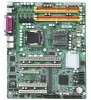
GA-4MXSV Motherboard Layout Introduction 5 P OO M UV L WX Y 6 E J 3D 4 K Z 7 C N FG H I A Q 2 R S T B 1 8 9 7 - Gigabyte GA-4MXSV | User Manual - Page 8
English GA-4MXSV Motherboard A. CPU B. Intel Mukilteo C. Intel 6702 PXH-V D. Intel ICH7R E. ITE IT8712F F. SATA1 G. SATA2 H. PCI-X_2 Y. PCI-X_1 Z. BAT (Battery) 1. ATX 2. ATX12V 3. WOR 4. WOL 5. UF1 (CPU FAN) 6. UF2 (System FAN) 7. UF3 (System FAN) 8. UF4 (System FAN) 9. UF5 (System FAN) 8 - Gigabyte GA-4MXSV | User Manual - Page 9
Introduction Chapter 2 Hardware Installation Process To set up your computer, you must complete the following steps: Step 1- Install the Central Processing Unit (CPU) Step 2- Install memory modules Step 3- Install expansion cards Step 4- Connect ribbon cables, cabinet wires, and power supply Step - Gigabyte GA-4MXSV | User Manual - Page 10
English GA-4MXSV Motherboard Step 1: Installing Processor and CPU Haet Sink Before installing the processor and cooling fan, cooling fan. 4. Please make sure the CPU type is supported by the motherboard. 5. If you do not match the CPU socket Pin 1 and CPU cut edge well, it will cause improper - Gigabyte GA-4MXSV | User Manual - Page 11
the CPU and make sure the push pins align to the pin hole on the motherboard.Push down the push pins diagonally. Fig. 4 Please make sure the Male and Female push pin are brought together. (for detailed installation instructions, please refer to the heatsink installation section of the user manual - Gigabyte GA-4MXSV | User Manual - Page 12
English GA-4MXSV Motherboard Step 2: Install memory modules Before installing the processor and heatsink, adhere to the following warning: When DIMM LED is ON, do not install/remove DIMM from socket. GA-4MXSV has 4 dual inline memory module (DIMM) socets. It supports the Dual Channel Technology. - Gigabyte GA-4MXSV | User Manual - Page 13
Table 1. Supported DIMM Module Type Hardware Installation Process Technology 256MB 512MB 1GB Organization 8MB x 8 x 4 bks 16MB x 4 x 4bks 16MB x 8 x 4bks 32MB x 4 x 4bks 32MB x 8 x 4bks 64MB x 4 x 4bks SDRAM Chips/ - Gigabyte GA-4MXSV | User Manual - Page 14
English GA-4MXSV Motherboard Step 3: Install expansion cards 1. Read the related expansion card's instruction document before install the expansion card 7. Power on the computer, if necessary, setup BIOS utility of expansion card from BIOS. 8. Install related driver from the operating system. 14 - Gigabyte GA-4MXSV | User Manual - Page 15
Hardware Installation Process Step 4: Connect ribbon cables, cabinet wires, and power supply Step 4-1 : I/O Back Panel Introduction 15 - Gigabyte GA-4MXSV | User Manual - Page 16
English GA-4MXSV Motherboard PS/2 Keyboard and PS/2 Mouse Connector To install a PS/2 USB interface. Also make sure your OS supports USB controller. If your OS does not support USB controller, please contact OS vendor for possible patch or driver updated. For more information please contact your - Gigabyte GA-4MXSV | User Manual - Page 17
S T C V GH I J K U A) ATX B) ATX _12V C) IDE1 D) FDC1 E) F_Panel F) COM2 G) USB2 H) S_ATA1 I) S_ATA2 J) S_ATA3 K) S_ATA4 L) WOL1 A R Q M) WOR1 N) UF1 (CPU Fan) O) UF2 (System Fan) P) UF3 (System Fan) Q) UF4 (System Fan) R) UF5 (System Fan) S) CLR_CMOS T) RECOVERY U) PASSWORD V) BAT (Battery) 17 - Gigabyte GA-4MXSV | User Manual - Page 18
English GA-4MXSV Motherboard A) ATX (ATX Power Connector) AC power cord should only be connected to your power supply unit after ATX power cable and other related devices are - Gigabyte GA-4MXSV | User Manual - Page 19
ribbon cable must be the same side with the Pin1. 1 39 2 40 D) FDC1 (Floppy Connector) Please connect the floppy drive ribbon cables to FDD. It supports 720K,1.2M,1.44M and 2.88Mbytes floppy disk types. The red stripe of the ribbon cable must be the same side with the Pin1. 12 33 - Gigabyte GA-4MXSV | User Manual - Page 20
English GA-4MXSV Motherboard E ) F_Panel1 (2X9 Pins Front Panel connector) Please connect the power LED, PC speaker, reset switch and power switch of your chassis front panel to the - Gigabyte GA-4MXSV | User Manual - Page 21
F ) COM2 Connector Introduction 12 9 10 Pin No. 1 2 3 4 5 6 7 8 9 10 Definition DCDSIN2 SOUT2 DTR2GND DSR2RTS2CTS2RI2NC G ) USB2 (Front USB Connector) Be careful with the polarity of the front panel USB connector. Check the pin assignment while you connect the front panel USB cable. Please - Gigabyte GA-4MXSV | User Manual - Page 22
English GA-4MXSV Motherboard H / I / J / K ) S_ATA1/ 2/ 3/ 4 (Serial ATA Connectors) You can connect the Serial ATA device to this manage the system that installed this mainboard via your network adapter which also supports WOL. Pin No. Definition 1 +5V SB 2 GND 3 Wake on Lan Signal 1 22 - Gigabyte GA-4MXSV | User Manual - Page 23
Pin No. Definition 1 MODEM RING ON 2 GND 1 N ) UF1 (CPU Fan Connector) Please note, a proper installation of the CPU cooler is essential to prevent the CPU from running under abnormal condition or damaged by overheating.The CPU fan connector supports Max. current up to 1A . 1 Pin No - Gigabyte GA-4MXSV | User Manual - Page 24
English GA-4MXSV Motherboard O / P / Q / R ) UF2/3/4/5 (System Fan Connectors) This connector allows you to link with the cooling fan on the system case to lower the system temperature. These connectors - Gigabyte GA-4MXSV | User Manual - Page 25
T ) RECOVERY ( BIOS Recovery Function) Connector Introduction 1 1-2 close: Enable BIOS Recovery function. 1 2-3 close: Disable this function. (Default value) Please remove the jumper when system access recovery flopp disk. U ) PASSWORD (Clear CMOS Password Function) Open: Clear Password Short: - Gigabyte GA-4MXSV | User Manual - Page 26
English GA-4MXSV Motherboard V ) BAT1 (Battery) CAUTION Danger of explosion if battery is incorrectly replaced. Replace only with the same or equivalent type recommended by the manufacturer. Dispose of used batteries according to the manufacturer's instructions. If you want to erase CMOS... 1.Turn - Gigabyte GA-4MXSV | User Manual - Page 27
the left hand Move to the item in the right hand Main Menu - Quit and not save changes into CMOS Status Page Setup Menu and Option Page Setup Menu - Exit current page and return to Main Menu Increase the numeric value or make changes Decrease the numeric value or - Gigabyte GA-4MXSV | User Manual - Page 28
GA-4MXSV Motherboard GETTINGHELP Main Menu The on-line description of the highlighted setup function is displayed at the bottom of the screen. Status Page Setup Menu / Option Page Setup Menu Press F1 to pop up a small help window that describes the appropriate keys to use and the possible selections - Gigabyte GA-4MXSV | User Manual - Page 29
Once you enter Phoenix BIOS Setup Utility, the Main Menu (Figure 1) will appear on the screen. Use arrow keys to select among the items and press to accept or enter - Gigabyte GA-4MXSV | User Manual - Page 30
GA-4MXSV Motherboard Legacy Diskette A/B This category identifies the type of floppy disk drive A that has been installed in the computer. Disabled Disable this device. 360KB, 51/4 in. 31/2 inch AT-type high-density drive; 360K byte : auto type, and manual type. Manual type is user-definable; - Gigabyte GA-4MXSV | User Manual - Page 31
BIOS Setup TYPE 1-39: Predefined types. Users: Set parameters by User. Auto: Set parameters The data transfer from and to the device occurs multiple sectors at a time if the device supports it. LBA Mode 32-Bit I/O Transfer Mode Ultra DMA Mode This field shows if the device type in the - Gigabyte GA-4MXSV | User Manual - Page 32
GA-4MXSV Motherboard Advanced Processor Options Figure 1-1: Advanced Processor Option Advanced Processor Option This category includes the information of CPU Speed, Processor ID, Processor L2 Cache. And setup menu for C1 Enhanced Mode, No Execute Mode Memory Protection, and Processor Power - Gigabyte GA-4MXSV | User Manual - Page 33
BIOS Setup C1 Enhanced Mode With enabling C1 Enhanced Mode, all loical processors in the physical processor have entered the C1 state, the processor will reduce the - Gigabyte GA-4MXSV | User Manual - Page 34
GA-4MXSV Motherboard Advanced About This Section: Advanced With this section, allowing user to configure your system for basic operation. User can change the processor options, chipset configuration, PCI configuration and chipset control. Figure 2: Advanced 34 - Gigabyte GA-4MXSV | User Manual - Page 35
Memory Configuration BIOS Setup Figure 2-1: Memory Configuration Installed Memory/Available to OS/DIMM Group 1,2,3,4 Status These category is display-only which is determined by POST (Power On Self Test) - Gigabyte GA-4MXSV | User Manual - Page 36
GA-4MXSV Motherboard PCI Configuration Figure 2-2: PCI Configuration EmbeddedNIC #1 Onboard LAN1 Control Enabled Enable onboard LAN1 device. (Default value) Disabled Disable this function. Option ROM Scan Enabled Enableing - Gigabyte GA-4MXSV | User Manual - Page 37
PCI Slot 1/2/3/4/5 Option ROM BIOS Setup Enabled Disabled Enableing this item to initialize device expansion ROM. (Defualt value) Disable this function. 37 - Gigabyte GA-4MXSV | User Manual - Page 38
GA-4MXSV Motherboard I/O Device Configuration Figure 2-3: I/O Device Configuration 38 - Gigabyte GA-4MXSV | User Manual - Page 39
IO address to 3E8. 2E8 Set IO address to 2E8. IRQ IRQ3 Set Interrupt as IRQ3. (Default value) IRQ4 Set Interrupt as IRQ4. 39 BIOS Setup - Gigabyte GA-4MXSV | User Manual - Page 40
GA-4MXSV Motherboard Parallel Port This allows users to configure parallel port by using ) IRQ7 Set Interrupt as IRQ7. (Default value) PS/2 Mouse Set this option 'Enabled' to allow BIOS support for a PS/2 - type mouse. Enabled 'Enabled' forces the PS/2 mouse port to be enabled regardless if - Gigabyte GA-4MXSV | User Manual - Page 41
BIOS Setup USB 2.0 Controller This item allows users to enable or disable the USB 2.0 device by setting item to the desired value. Enabled Enable USB 2.0 controller. (Default value) Options Disbale this function. Legacy USB Support This option allows user to function support for legacy USB. - Gigabyte GA-4MXSV | User Manual - Page 42
GA-4MXSV Motherboard Serial ATA Enabled Disabled Enables on-board serial ATA function. (Default this item to enable SATA AHCI function for WinXP-SP1+IAA driver supports AHCI mode. Disabled this function. ` SATA RAID Enable Enabled Enabled SATA RAID function. Disabled Disable this function. 42 - Gigabyte GA-4MXSV | User Manual - Page 43
Advanced Chipset Control BIOS Setup Figure 2-4: Advanced Chipset Control Enable Multimedia Timer Enabled Enable Multimedia Timer support. Disabled Disable this function. (Default value) PCI Express Sub-Menu These items are for debugging the PCI-Express Ports. PCI Device ` PCI IRQ Line - Gigabyte GA-4MXSV | User Manual - Page 44
GA-4MXSV Motherboard Wake On LAN / PME This option allow user to determine the action of the system when a LAN/PME wake up event occurs. Enabled Enable Wake - Gigabyte GA-4MXSV | User Manual - Page 45
Hardware Monitor BIOS Setup Figure 2-5: Hardware Monitor CPU / Motherboard/ Ambit Temperature Display the current CPU temperature, Motherboard, and Ambient temperature. Voltage Monitor: 3V Dual, VCC3, VCC, 12V2, 12V1, VBAT, 5VSB Detect system's voltage status automatically. FAN Monitor: System - Gigabyte GA-4MXSV | User Manual - Page 46
GA-4MXSV Motherboard Boot -time Diagnostic When this item is enabled, system will shows Diagnostic status when (MP) specification revision level. Some operating system will require 1.1 for compatibility reasons. 1.4 Support MPS Version 1.4 . (Default value) 1.1 Support M PS Version 1.1. 46 - Gigabyte GA-4MXSV | User Manual - Page 47
Security BIOS Setup * About This Section: Security In this section, user can set either Set User Password You can only enter but do not have the right to change the options of the setup menus. When you select this function, the following message will appear at the center of the screen to - Gigabyte GA-4MXSV | User Manual - Page 48
GA-4MXSV Motherboard Set Supervisor Password You can install and change this options for the setup menus. Type the password up to 6 characters in lengh and press . The password typed now will clear any previously entered password from the CMOS - Gigabyte GA-4MXSV | User Manual - Page 49
Server BIOS Setup Figure 4: Server 49 - Gigabyte GA-4MXSV | User Manual - Page 50
GA-4MXSV Motherboard System Management Figure 4-1: System Management Server Management This category allows user to view the server management features. Including information of BIOS Version. All items in - Gigabyte GA-4MXSV | User Manual - Page 51
Console Redirection BIOS Setup Figure 4-2: Console Redirection BIOS Redirection Port If this option is set to enabled, it will use a port on the motherboard. On-board COMA Use COMA as he COM port address. Disabled Disable this function. (Default value) Note: Tower has COMA and COMB. Baud - Gigabyte GA-4MXSV | User Manual - Page 52
GA-4MXSV Motherboard Flow Control This option provide user to enable the flow control function. None Not supported. XON/OFF Software control function. (Default value) Event Log Confuguration This option contains additional setup menu to configure the Event Log Configuration. ` Clear all - Gigabyte GA-4MXSV | User Manual - Page 53
BIOS Setup Post Error Pause If this item is set to enabled, the system will wai for user intervention on critical POST errors. If this item is - Gigabyte GA-4MXSV | User Manual - Page 54
GA-4MXSV Motherboard Event Log Viewer Enabled Enable Event Log Viewer function(Default value) Disabled Disable this function. This option will disappear and disable when BMC module is populated. 54 - Gigabyte GA-4MXSV | User Manual - Page 55
Set Threshold BIOS Setup Figure 4-4: Set Threshold System Fan 1/2/3/4/5/6 Error Enabled Enable System Fan 1/2/3/4/5/6 Fan Error. (Default value) Disabled Disable this function. M/B Voltage Error Enabled Motherboard Voltage Error. (Default value) Disabled Disable this function. M/B - Gigabyte GA-4MXSV | User Manual - Page 56
GA-4MXSV Motherboard Boot * About This Section: Boot The "Boot" menu allows user to select among four possible types of boot devices listed using the up and down - Gigabyte GA-4MXSV | User Manual - Page 57
Figure 6: Exit * About This Section: Exit Once you have changed all of the set values in the BIOS setup, you should save your chnages and exit BIOS setup program. Select "Exit" from the menu bar, to display the following sub-menu. Exit Saving Changes Exit Discarding Changes Load Settup Default - Gigabyte GA-4MXSV | User Manual - Page 58
GA-4MXSV Motherboard Exit Saving Changes This option allows user to exit system setup with saving the changes. Press on this . Exit Discarding Changes This option allows user to exit system setup without changing any previous settings values in CMOS. The previous selection remain in effect. This - Gigabyte GA-4MXSV | User Manual - Page 59
item, you will get a confirmation dialog box with a message as below: Discard Changes This option allows user to load previos values from CMOS for all setup item. When you press on this item, you will get a confirmation dialog box with a message as below: 59 - Gigabyte GA-4MXSV | User Manual - Page 60
GA-4MXSV Motherboard Save Changes This option allows user to save setup dat ato CMOS. When you press on this item, you will get a confirmation dialog box with a message as below: Press [Yes] to save setup daya to CMOS. 60 - Gigabyte GA-4MXSV | User Manual - Page 61
RCehvaispitoenr H4isTtoercyhnical Reference Block Diagram Clock Generator CK410 ICS 95410DF PCIE x 8 PCI-X 100MHz PCI-X 100MHz PCI-E x8 Intel LGA775 Smithfield 1066MT/S FSB Mukilteo MCH VID0~5 VRD 10.1 Channel A DDRII533/667 Unbuffered ECC DIMM x 2 Channel B DDRII533/667 Unbuffered ECC DIMM x - Gigabyte GA-4MXSV | User Manual - Page 62
GA-4MXSV Motherboard RCehvaispitoenr H5istDoriyver Installation A. Intel Chipset Software Installation Utilities Insert the driver CD-title that came with your motherboard into your CD-ROM driver, the driver CD-title will auto start and show a series of Setup Wizard dialog boxes. If not, please - Gigabyte GA-4MXSV | User Manual - Page 63
Installation Completed Driver Installation 5. Installation completed, Click "Finish" to restart computer. (5) 63 - Gigabyte GA-4MXSV | User Manual - Page 64
GA-4MXSV Motherboard B. Intel LAN Driver Installation Insert the driver CD-title that came with your motherboard into your CD-ROM driver, the driver CD-title will auto start and show a series of Setup Wizard dialog boxes. If not, please double click the CD-ROM device icon in "My computer", and - Gigabyte GA-4MXSV | User Manual - Page 65
Install Option Start Installation Driver Installation 5.Click "Next". (5) Installation Progress 6.Click "Install". (6) Installation Complete Starting Installation (7) 8.Click "Install". (8) 65 - Gigabyte GA-4MXSV | User Manual - Page 66
GA-4MXSV Motherboard C. Intel Host RAID Driver Installation Installation Procedures: 1. The CD auto run program starts, Double click on "Intel Host RAID Driver" to make a driver disk. 2. Select a folder refering to your operating system. 3. Insert a flopp disk in the floppy drive. 4. Click on the - Gigabyte GA-4MXSV | User Manual - Page 67
Formatting and writing in floppy sidk Driver Installation (5) 67 - Gigabyte GA-4MXSV | User Manual - Page 68
GA-4MXSV Motherboard D. VGA ES1000 Driver Installation Insert the driver CD-title that came with your motherboard into your CD-ROM driver, the driver CD-title will auto start and show a series of Setup Wizard dialog boxes. If not, please double click the CD-ROM device icon in "My computer", and - Gigabyte GA-4MXSV | User Manual - Page 69
9.0 Driver Installation Driver Installation Insert the driver CD-title that came with your motherboard into your CD-ROM driver, the driver CD-title will auto start and show the installation guide. If not, please double click the CD-ROM device icon in "My computer", and execute the setup.exe - Gigabyte GA-4MXSV | User Manual - Page 70
GA-4MXSV Motherboard RCehvaispitoenr H6istAoprypendix Acronyms Acronyms Meaning ACPI Advanced Configuration and Power Riser BBS BIOS Boot Specification BIOS Basic Input / Output System CPU Central Processing Unit CMOS Complementary Metal Oxide Semiconductor CRIMM Continuity RIMM CNR - Gigabyte GA-4MXSV | User Manual - Page 71
Manufacturer PCI A.G.P. Controller Power-On Self Test Peripheral Component Interconnect Rambus in-line Memory Module Special Circumstance Instructions Single Edge Contact Cartridge Static Random Access Memory Symmetric Multi-Processing System Management Interrupt Universal Serial Bus Voltage
-
 1
1 -
 2
2 -
 3
3 -
 4
4 -
 5
5 -
 6
6 -
 7
7 -
8
-
9
-
10
-
11
-
12
-
13
-
14
-
15
-
16
-
17
-
18
-
19
-
20
-
21
-
22
-
23
-
24
-
25
-
26
-
27
-
28
-
29
-
30
-
31
-
32
-
33
-
34
-
35
-
36
-
37
-
38
-
39
-
40
-
41
-
42
-
43
-
44
-
45
-
46
-
47
-
48
-
49
-
50
-
51
-
52
-
53
-
54
-
55
-
56
-
57
-
58
-
59
-
60
-
61
-
62
-
63
-
64
-
65
-
66
-
67
-
68
-
69
-
70
-
71
 |
 |

USER’S MANUAL
GA-4MXSV
Pentium Prescott 1066 Motherboard
Pentium
®
Prescott Processor Motherboard
Rev. 1002
12ME-4MXSV-1002