Gigabyte GA-8I915GM-G Manual
Gigabyte GA-8I915GM-G Manual
 |
View all Gigabyte GA-8I915GM-G manuals
Add to My Manuals
Save this manual to your list of manuals |
Gigabyte GA-8I915GM-G manual content summary:
- Gigabyte GA-8I915GM-G | Manual - Page 1
-8I915G-MF GA-8I915GM GA-8I915GM-G Intel® Pentium® 4 LGA775 Processor Motherboard User's Manual Rev. 2203 12ME-8I915GMF-2203 * The WEEE marking on the product indicates this product must not be disposed of with user's other household waste and must be handed over - Gigabyte GA-8I915GM-G | Manual - Page 2
Motherboard GA-8I915G-MF Jun. 11, 2004 Motherboard GA-8I915G-MF Jun. 11, 2004 - Gigabyte GA-8I915GM-G | Manual - Page 3
: „ For detailed product information and specifications, please carefully read the "Product User Manual". „ For detailed information related to Gigabyte's unique features, please go to the "Technology Guide" section on Gigabyte's website to read or download the information you need. For more product - Gigabyte GA-8I915GM-G | Manual - Page 4
Table of Content GA-8I915G-MF Motherboard Layout 6 Block Diagram ...7 Chapter 1 Hardware Installation 9 1-1 Considerations Prior to Installation 9 1-2 Feature Summary 10 1-3 Installation of the CPU and Heatsink 12 1-3-1 Installation of the CPU 12 1-3-2 Installation of the Heatsink 13 1-4 - Gigabyte GA-8I915GM-G | Manual - Page 5
3-3 Driver CD Information 48 3-4 Hardware Information 49 3-5 Contact Us ...49 Chapter 4 Appendix 51 4-1 Unique Software Utilities 51 4-1-1 Xpress Recovery Introduction 52 4-1-2 Flash BIOS Method Introduction 55 4-1-3 2- / 4- / 6- / 8- Channel Audio Function Introduction 64 4-2 Troubleshooting - Gigabyte GA-8I915GM-G | Manual - Page 6
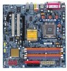
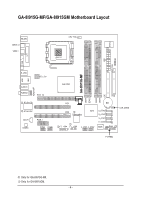
GA-8I915G-MF/GA-8I915GM Motherboard Layout IT8712 KB_MS SPDIF_O SPDIF_I CPU_FAN LGA775 SYS_FAN IR ATX VGA LPT R_USB ATX_12V USB LAN AZALIA_FP AUDIO1 AUDIO2 PCIE_16 RTL8110S RTL8100C CD_IN CODEC PCIE_1 COMA COMB GA-8I915G-MF DDR1 DDR2 Intel 915G IDE FDD DDR3 DDR4 PCI1 PCI2 ICH6 - Gigabyte GA-8I915GM-G | Manual - Page 7
Block Diagram PCI-ECLK VGA (100MHz) PCI Express x16 1 PCIExpress x 915G GMCH Dual Channel Memory GMCHCLK (133/200MHz) 66MHz 33MHz 14.318MHz 48MHz BIOS 4 Serial ATA Intel ATA33/66/100 ICH6 IDE Channels Floppy IT 8712 LPT PCICLK (33MHz) Only for GA-8I915G-MF. Only for GA-8I915GM. - 7 - - Gigabyte GA-8I915GM-G | Manual - Page 8
Only for GA-8I915GM-G 1-2 Feature Summary Onboard LAN Š Onboard Realtek 8110S chip (10/100/1000 Mbit) CI (Chassis Intrusion, Case Open) This 2-pin connector allows your system to enable or disable the "Case Open" item in BIOS, if the system case begin remove. Pin No. Definition 1 Signal 1 2 - Gigabyte GA-8I915GM-G | Manual - Page 9
instructions below: 1. Please turn off the computer and unplug its power cord. 2. When handling the motherboard , avoid touching any metal leads or connectors. 3. It is best to wear an electrostatic discharge (ESD) cuff when handling electronic components (CPU motherboard problem manual - Gigabyte GA-8I915GM-G | Manual - Page 10
Audio I/O Control Š Supports the latest Intel® Pentium® 4 LGA775 CPU Š Supports 800/533MHz FSB Š L2 cache varies with CPU connections Š 1 parallel port supporting Normal/EPP/ECP mode Š 1 VGA port, onboard COMA/COMB GA-8I915G-MF. Only for GA-8I915GM. GA-8I915G-MF/GA-8I915GM Motherboard - 10 - - Gigabyte GA-8I915GM-G | Manual - Page 11
Š CPU temperature detection Š CPU / System fan speed detection Š CPU warning temperature Š CPU / System fan failure warning Š CPU smart fan control BIOS Š Use of licensed AWARD BIOS Š Supports Q-Flash Additional Features Š Supports @BIOS Š Supports EasyTune5 (only supports Hardware - Gigabyte GA-8I915GM-G | Manual - Page 12
- CPU: An Intel® Pentium 4 Processor with HT Technology - Chipset: An Intel® Chipset that supports HT Technology - BIOS: A BIOS that supports HT might cause damage to the CPU during installation.) GA-8I915G-MF/GA-8I915GM Motherboard - 12 - Fig. 4 Once the CPU is properly inserted, please replace - Gigabyte GA-8I915GM-G | Manual - Page 13
the CPU and make sure the push pins aim to the pin hole on the motherboard.Pressing down the push pins diagonally. Fig. 4 Please make sure the Male and Female push pin are joined closely. (for detailed installation instructions, please refer to the heatsink installation section of the user manual - Gigabyte GA-8I915GM-G | Manual - Page 14
are unable to insert the module, please switch the direction. The motherboard supports DDR memory modules, whereby BIOS will automatically detect memory capacity and specifications. Memory modules are designed so when you wish to remove the DIMM module. GA-8I915G-MF/GA-8I915GM Motherboard - 14 - - Gigabyte GA-8I915GM-G | Manual - Page 15
English GA-8I915G-MF/GA-8I915GM supports the Dual Channel Technology. After operating the Dual Channel Technology, the bandwidth of Memory Bus will double. GA-8I915G-MF/GA-8I915GM includes 4 DIMM sockets, and each Channel has two DIMM sockets as following: Channel A : DDR 1, DDR 2 Channel B : DDR - Gigabyte GA-8I915GM-G | Manual - Page 16
's instruction document BIOS utility of expansion card from BIOS. 8. Install related driver VGA card. Please align the VGA card to the onboard PCI Express x 16 slot and press firmly down on the slot .Make sure your VGA card is locked by the small white-drawable bar. GA-8I915G-MF/GA-8I915GM Motherboard - Gigabyte GA-8I915GM-G | Manual - Page 17
capable of providing digital audio to external speakers or function. VGA Port Monitor can be connected to VGA port supports USB controller. If your OS does not support USB controller, please contact OS vendor for possible patch or driver GA-8I915G-MF. Only for GA-8I915GM. - 17 - Hardware Installation - Gigabyte GA-8I915GM-G | Manual - Page 18
the side surround speakers to this connector. You can use audio software to configure 2-/4-/6-/8-channel audio functioning. 1-7 Connectors Introduction 3 2 14 4 1 5 S_ATA2 / S_ATA3 16) CLR_CMOS 8) F_PANEL 17) BAT 9) PWR_LED Only for GA-8I915G-MF. GA-8I915G-MF/GA-8I915GM Motherboard - 18 - - Gigabyte GA-8I915GM-G | Manual - Page 19
all components and devices are properly installed. Align the power connector with its proper location on the motherboard and connect tightly. The ATX_12V power connector mainly supplies power to the CPU. If the ATX_12V power connector is not connected, the system will not start. Caution! Please use - Gigabyte GA-8I915GM-G | Manual - Page 20
Caution! Please remember to connect the power to the CPU fan to prevent CPU overheating and failure. 1 CPU_FAN 1 SYS_FAN Pin No supported are: 360KB, 720KB, 1.2MB, 1.44MB and 2.88MB. Please connect the red power connector wire to the pin1 position. 34 33 2 1 GA-8I915G-MF/GA-8I915GM Motherboard - Gigabyte GA-8I915GM-G | Manual - Page 21
other as Slave (for information on settings, please refer to the instructions located on the IDE device). 40 39 2 1 7) S_ATA0/ can provide 150MB/s transfer rate. Please refer to the BIOS setting for the Serial ATA and install the proper driver in order to work properly. Pin No. Definition 1 - Gigabyte GA-8I915GM-G | Manual - Page 22
2- Pin 3: NC Pin 4: Data(-) Open: Normal Operation Close: Reset Hardware System Open: Normal Operation Close: Power On/Off Pin 1: LED anode(+) Pin 2: LED cathode(-) NC GA-8I915G-MF/GA-8I915GM Motherboard - 22 - - Gigabyte GA-8I915GM-G | Manual - Page 23
Audio Connector) This connector is supported to connect HD(High Definition) Audio and AC'97 Audio. Check the pin assignment carefully while you connect the audio N/A 10 Line Out (L) HD Audio is the default setting for this connector. To enable AC'97 Audio, from BIOS settings, set Front Panel Type - Gigabyte GA-8I915GM-G | Manual - Page 24
) CD_IN (CD IN) Connect CD-ROM or DVD-ROM audio out to the connector. 1 Pin No. Definition 1 CD supported by rear USB ports. Pin No. Definition 1 Power 2 Power 9 1 3 USB DX- 4 USB Dy- 10 2 5 USB DX+ 6 USB Dy+ 7 GND 8 GND 9 No Pin 10 NC GA-8I915G-MF/GA-8I915GM Motherboard - Gigabyte GA-8I915GM-G | Manual - Page 25
connect the IR. Please contact your nearest dealer for optional IR device. Pin No. Definition 1 VCC 2 No Pin 3 IR RX 1 4 GND 5 IR TX Only for GA-8I915G-MF. - 25 - Hardware Installation - Gigabyte GA-8I915GM-G | Manual - Page 26
this jumper. To clear CMOS, temporarily short 1-2 pin. Default doesn't include the "Shunter" to prevent from improper use this jumper. 1 Open: Normal 1 Short :Clear CMOS GA-8I915G-MF/GA-8I915GM Motherboard - 26 - - Gigabyte GA-8I915GM-G | Manual - Page 27
is incorrectly replaced. Replace only with the same or equivalent type recommended by the manufacturer. Dispose of used batteries according to the manufacturer's instructions. If you want to erase CMOS... 1.Turn OFF the computer and unplug the power cord. 2.Remove the battery, wait for 30 second - Gigabyte GA-8I915GM-G | Manual - Page 28
English GA-8I915G-MF/GA-8I915GM Motherboard - 28 - - Gigabyte GA-8I915GM-G | Manual - Page 29
its original settings. If you wish to upgrade to a new BIOS, either Gigabyte's Q-Flash or @BIOS utility can be used. Q-Flash allows the user to quickly and easily update or backup BIOS without entering the operating system. @BIOS is a Windows-based utility that does not require users to boot to DOS - Gigabyte GA-8I915GM-G | Manual - Page 30
search the advanced option hidden. Please Load Optimized Defaults in the BIOS when somehow the system works not stable as usual. This action „ MB Intelligent Tweaker(M.I.T.) This setup page is control CPU clock and frequency ratio. „ Load Fail-Safe Defaults GA-8I915G-MF/GA-8I915GM Motherboard - 30 - - Gigabyte GA-8I915GM-G | Manual - Page 31
English „ Set User Password Change, set, or disable password. It allows you to limit access to the system. „ Save & Exit Setup Save CMOS value settings to CMOS and exit setup. „ Exit Without Saving Abandon all CMOS value changes and exit setup. - 31 - BIOS Setup - Gigabyte GA-8I915GM-G | Manual - Page 32
>, . Week The week, from Sun to Sat, determined by the BIOS and is display only Month The month, Jan. Through Dec. Day The step and allow for faster system start up. Manual User can manually input the correct settings Access Mode Use this to GA-8I915G-MF/GA-8I915GM Motherboard - 32 - - Gigabyte GA-8I915GM-G | Manual - Page 33
88M byte capacity. Floppy 3 Mode Support (for Japan Area) Disabled Normal be prompted. Whenever the BIOS detects a non-fatal error the BIOS. Base Memory The POST of the BIOS will motherboard, or 640K for systems with 640K or more memory installed on the motherboard. Extended Memory The BIOS - Gigabyte GA-8I915GM-G | Manual - Page 34
your boot device priority by LAN. Disabled Select your boot device priority by Disabled. (Note) This item will show up when you install a processor which supports this function. GA-8I915G-MF/GA-8I915GM Motherboard - 34 - - Gigabyte GA-8I915GM-G | Manual - Page 35
function. (Default value) CPU Thermal Monitor 2 (TM2) (Note ) Enabled Enable CPU Thermal Monitor 2 (TM2) function. Disabled Disable CPU Thermal Monitor 2 (TM2) function. (Default value) (Note) This item will show up when you install a processor which supports this function. - 35 - BIOS Setup - Gigabyte GA-8I915GM-G | Manual - Page 36
Support USB Mouse Support Audio] motherboard; 2 for SATA and the other for PATA IDE. Set On-Chip SATA mode to Enhanced, the motherboard allows up to 6 HDDs to use. Set On-Chip SATA mode to Non-Combined, SATA will be simulated to Only for GA-8I915G-MF. PATA mode. GA-8I915G-MF/GA-8I915GM Motherboard - Gigabyte GA-8I915GM-G | Manual - Page 37
Support. (Default value) USB Mouse Support Enabled Enable USB Mouse Support. Disabled Disable USB Mouse Support. (Default value) Azalia Codec Auto Auto detect Azalia audio function. (Default value) Disabled Disable Azalia audio . (Default value) Only for GA-8I915G-MF. - 37 - BIOS Setup - Gigabyte GA-8I915GM-G | Manual - Page 38
port 1 and address is 2E8. Disabled Disable onboard Serial port 1. Onboard Serial Port 2 Auto BIOS will automatically setup the port 2 address. 3F8/IRQ4 Enable onboard Serial port 2 and address DMA to 3. (Default value) 1 Set ECP Mode Use DMA to 1. GA-8I915G-MF/GA-8I915GM Motherboard - 38 - - Gigabyte GA-8I915GM-G | Manual - Page 39
) Power On By Mouse Disabled Disable this function. (Default value) Double Click Double click on PS/2 mouse left button to power on the system. - 39 - BIOS Setup - Gigabyte GA-8I915GM-G | Manual - Page 40
system always in "On" state. Memory When AC-power back to the system, the system will return to the Last state before AC-power off. GA-8I915G-MF/GA-8I915GM Motherboard - 40 - - Gigabyte GA-8I915GM-G | Manual - Page 41
IRQ 3,4,5,7,9,10,11,12,14,15 to PCI 1. Auto assign IRQ to PCI 2. (Default value) Set IRQ 3,4,5,7,9,10,11,12,14,15 to PCI 2. - 41 - BIOS Setup - Gigabyte GA-8I915GM-G | Manual - Page 42
operate at full speed. b. When the CPU temperature is between 20 and 65 degrees Celsius, the CPU fan speed will change depending on the actual CPU temperature. c. When the CPU temperature is lower than 20 degrees Celsius, CPU fan will stop spinning. GA-8I915G-MF/GA-8I915GM Motherboard - 42 - - Gigabyte GA-8I915GM-G | Manual - Page 43
FAN Mode This option is available only when CPU Smart FAN Control is enabled. Auto BIOS autodetects the type of CPU fan you installed and sets the optimal CPU Smart FAN control mode for it. (Default value) Voltage Set to Voltage when you use a CPU fan with a 3-pin fan power cable. PWM Set - Gigabyte GA-8I915GM-G | Manual - Page 44
Standard CMOS Features Load Fail-Safe Defaults ` Advanced BIOS Features Load Optimized Defaults ` Integrated Peripherals Set Supervisor this field loads the factory defaults for BIOS and Chipset Features which the system automatically detects. GA-8I915G-MF/GA-8I915GM Motherboard - 44 - - Gigabyte GA-8I915GM-G | Manual - Page 45
/Set/Disable Password Selecting this field loads the factory defaults for BIOS and Chipset Features which the system automatically detects. When you select basic items. If you select "System" at "Password Check" in Advance BIOS Features Menu, you will be prompted for the password every time the - Gigabyte GA-8I915GM-G | Manual - Page 46
2004 Award Software ` Standard CMOS Features Load Fail-Safe Defaults ` Advanced BIOS Features Load Optimized Defaults ` Integrated Peripherals Set Supervisor Password ` Power Management saving to RTC CMOS. Type "N" will return to Setup Utility. GA-8I915G-MF/GA-8I915GM Motherboard - 46 - - Gigabyte GA-8I915GM-G | Manual - Page 47
will continue to install other drivers. System will reboot automatically after install the drivers, afterward you can install others application. For USB2.0 driver support under Windows XP operating system, please use Windows Service Pack. After install Windows Service Pack, it will show a question - Gigabyte GA-8I915GM-G | Manual - Page 48
This page displays all the tools that Gigabyte developed and some free software, you can choose anyone you want and press "install" to install them. 3-3 Driver CD Information This page lists the contents of software and drivers in this CD-title. GA-8I915G-MF/GA-8I915GM Motherboard - 48 - - Gigabyte GA-8I915GM-G | Manual - Page 49
English 3-4 Hardware Information This page lists all device you have for this motherboard. F5 3-5 Contact Us Please see the last page for details. - 49 - Install Drivers - Gigabyte GA-8I915GM-G | Manual - Page 50
English GA-8I915G-MF/GA-8I915GM Motherboard - 50 - - Gigabyte GA-8I915GM-G | Manual - Page 51
) Motherboard Intelligent Tweaker (M.I.T.) allows user to access and change BIOS feature settings with relative speed and ease. Through GIGABYTE M.I.T. feature the user is no longer required to switch into different modes within BIOS setup in order to change system settings such as the CPU system - Gigabyte GA-8I915GM-G | Manual - Page 52
functions status 9. GIGABYTE Logo Log on to GIGABYTE website 10. Help button Display EasyTuneTM 5 Help file 11. Exit or Minimize button Quit or Minimize EasyTuneTM 5 software (Note) EasyTune 5 functions may vary depending on different motherboards. GA-8I915G-MF/GA-8I915GM Motherboard - 52 - - Gigabyte GA-8I915GM-G | Manual - Page 53
be used with an IDE hard disk supporting HPA 5. The first partition must be BIOS menu, select "Advanced BIOS Feature" and set to boot from CD-ROM. Insert the provided driver CD into your CD drive, then save and exit the BIOS V1.0 (C) Copy Right 2003. GIGABYTE Technology CO. , Ltd. 1. Execute - Gigabyte GA-8I915GM-G | Manual - Page 54
as well as drive reading/writing speed will affect backup speed. 3. It is recommended that Xpress Recovery be immediately installed after OS and all required driver and software installations are complete. GA-8I915G-MF/GA-8I915GM Motherboard - 54 - - Gigabyte GA-8I915GM-G | Manual - Page 55
Esc to Exit The backup utility will automatically scan your system and back up data as a backup image in your hard drive. Not all systems support access to Xpress Recovery by pressing the F9 key during computer power on. If this is the case, please use the boot from CD-ROM - Gigabyte GA-8I915GM-G | Manual - Page 56
of Gigabyte motherboards are equipped with dual BIOS. In the BIOS menu of the motherboards supporting Q-Flash and Dual BIOS, the Q-Flash utility and Dual BIOS utility are combined in the same screen. This section only deals with how to use Q-Flash utility. In the following sections, we take GA-8KNXP - Gigabyte GA-8I915GM-G | Manual - Page 57
Backup Load Default Settings Save Settings to CMOS Q-Flash Utility Load Main BIOS from Floppy Load Backup BIOS from Floppy Save Main BIOS to Floppy Save Backup BIOS to Floppy Enter : Run :Move ESC:Reset F10:Power Off Dual BIOS utility bar Q-FlashTM utility title bar Action bar Task menu for - Gigabyte GA-8I915GM-G | Manual - Page 58
Main BIOS to Floppy Save Backup BIOS to Floppy Enter : Run :Move ESC:Reset F10:Power Off Do not trun off power or reset your system at this stage!! After BIOS file is read, you'll see a confirmation dialog box asking you "Are you sure to update BIOS?" GA-8I915G-MF/GA-8I915GM Motherboard - 58 - Gigabyte GA-8I915GM-G | Manual - Page 59
: Run :Move ESC:Reset F10:Power Off After system reboots, you may find the BIOS version on your boot screen becomes the one you flashed. The BIOS file becomes Fab after updating. Award Modular BIOS v6.00PG, An Energy Star Ally Copyright (C) 1984-2003, Award Software, Inc. Intel i875P AGPset - Gigabyte GA-8I915GM-G | Manual - Page 60
and exit. Part Two: Updating BIOS with Q-FlashTM Utility on Single-BIOS Motherboards. This part guides users of single-BIOS motherboards how to update BIOS using the Q-FlashTM utility. CMOS Language F10: Save & Exit Setup Time, Date, Hard Disk Type... GA-8I915G-MF/GA-8I915GM Motherboard - 60 - - Gigabyte GA-8I915GM-G | Manual - Page 61
using the Q-Flash utility. As described in the "Before you begin" section above, you must prepare a floppy disk having the BIOS file for your motherboard and insert it to your computer. If you have already put the floppy disk into your system and have entered the Q-Flash utility, please follow - Gigabyte GA-8I915GM-G | Manual - Page 62
2003-I845GE-6A69YG01C-00 6. Press Del to enter BIOS menu after system reboots and "Load BIOS Fail-Safe Defaults". See how to Load BIOS Fail-Safe Defaults, please kindly refer to Step 6 to 7 in Part One. Congratulation!! You have updated BIOS successfully!! GA-8I915G-MF/GA-8I915GM Motherboard - 62 - - Gigabyte GA-8I915GM-G | Manual - Page 63
the new @BIOS utility. @BIOS allows users to update their BIOS under Windows. Just select the desired @BIOS server to download the latest version of BIOS. Fig 1. Installing the @BIOS utility Fig 2. Installation Complete and Run @BIOS Click Sart/ Programs/ GIGABYTE/@BIOS Select @BIOS item than - Gigabyte GA-8I915GM-G | Manual - Page 64
boot. III. In method I, if the BIOS file you need cannot be found in @BIOSTM server, please go onto Gigabyte's web site for downloading and updating it according to method II. IV. Please note that any interruption during updating will cause system unbooted GA-8I915G-MF/GA-8I915GM Motherboard - 64 - - Gigabyte GA-8I915GM-G | Manual - Page 65
Windows XP) If you set the Front Panel Type option to HD Audio in BIOS, make sure to connect your audio front panel cable(optional for different models) connector to the motherboard ". Line Out STEP 2 : Following installation of the audio driver, you find a Sound Effect icon on the lower right - Gigabyte GA-8I915GM-G | Manual - Page 66
of the audio driver, you find a Sound Effect icon on the lower right hand taskbar. Click the icon to select the function. STEP 3: Click "Speaker Configuration" then click on the left selection bar and select "4CH Speaker" to complete 4 channel audio configuration. GA-8I915G-MF/GA-8I915GM Motherboard - Gigabyte GA-8I915GM-G | Manual - Page 67
the rear channels to "Rear Speaker Out", and the Center/Subwoofer channels to "Center/Subwoofer Speaker Out". STEP 2 : Following installation of the audio driver, you find a Sound Effect icon on the lower right hand taskbar. Click the icon to select the function. STEP 3: Click "Speaker Configuration - Gigabyte GA-8I915GM-G | Manual - Page 68
Following installation of the audio driver, you find a audio configuration. Sound Effect Configuration: At the sound effect menu, users can adjust sound option settings as desired. Front Speaker Out Rear Speaker Out Center/Subwoofer Speaker Out Side Speaker Out GA-8I915G-MF/GA-8I915GM Motherboard - Gigabyte GA-8I915GM-G | Manual - Page 69
Troubleshooting Below is a collection of general asked questions. To check general asked questions based on a specific motherboard model, please log on to http://www.gigabyte.com.tw Question 1: I cannot see some options that were included in previous BIOS after updating BIOS in the manual. If your - Gigabyte GA-8I915GM-G | Manual - Page 70
English GA-8I915G-MF/GA-8I915GM Motherboard - 70 - - Gigabyte GA-8I915GM-G | Manual - Page 71
- 71 - Appendix English - Gigabyte GA-8I915GM-G | Manual - Page 72
English GA-8I915G-MF/GA-8I915GM Motherboard - 72 - - Gigabyte GA-8I915GM-G | Manual - Page 73
- 73 - Appendix English - Gigabyte GA-8I915GM-G | Manual - Page 74
English GA-8I915G-MF/GA-8I915GM Motherboard - 74 - - Gigabyte GA-8I915GM-G | Manual - Page 75
- 75 - Appendix English - Gigabyte GA-8I915GM-G | Manual - Page 76
English GA-8I915G-MF/GA-8I915GM Motherboard - 76 - - Gigabyte GA-8I915GM-G | Manual - Page 77
- 77 - Appendix English - Gigabyte GA-8I915GM-G | Manual - Page 78
English GA-8I915G-MF/GA-8I915GM Motherboard - 78 - - Gigabyte GA-8I915GM-G | Manual - Page 79
.giga-byte.com U.S.A. G.B.T. INC. TEL: +1-626-854-9338 FAX: +1-626-854-9339 Tech. Support : http://tw.giga-byte.com/TechSupport/ServiceCenter.htm Non-Tech. Support(Sales/Marketing) : http://ggts.gigabyte.com.tw/nontech.asp WEB address : http://www.giga-byte.com Germany G.B.T. TECHNOLOGY TRADING GMBH - Gigabyte GA-8I915GM-G | Manual - Page 80
Representative Office Of GIGA-BYTE Technology Co., Ltd. in Romania Tech. Support : http://tw.giga-byte.com/TechSupport/ServiceCenter.htm Non-Tech. Support(Sales/Marketing) : http://ggts.gigabyte.com.tw/nontech.asp WEB address: http://www.gigabyte.com.ro GA-8I915G-MF/GA-8I915GM Motherboard - 80 -
-
 1
1 -
 2
2 -
 3
3 -
 4
4 -
 5
5 -
 6
6 -
 7
7 -
8
-
9
-
10
-
11
-
12
-
13
-
14
-
15
-
16
-
17
-
18
-
19
-
20
-
21
-
22
-
23
-
24
-
25
-
26
-
27
-
28
-
29
-
30
-
31
-
32
-
33
-
34
-
35
-
36
-
37
-
38
-
39
-
40
-
41
-
42
-
43
-
44
-
45
-
46
-
47
-
48
-
49
-
50
-
51
-
52
-
53
-
54
-
55
-
56
-
57
-
58
-
59
-
60
-
61
-
62
-
63
-
64
-
65
-
66
-
67
-
68
-
69
-
70
-
71
-
72
-
73
-
74
-
75
-
76
-
77
-
78
-
79
-
80
 |
 |

GA-8I915G-MF
GA-8I915GM
GA-8I915GM-G
Intel
®
Pentium
®
4 LGA775 Processor Motherboard
User's Manual
Rev. 2203
12ME-8I915GMF-2203
*
The WEEE marking on the product indicates this product must not be disposed of with user's other household waste
and must be handed over to a designated collection point for the recycling of waste electrical and electronic equipment!!
*
The WEEE marking applies only in European Union's member states.