Gigabyte GA-G31MF-S2 Manual
Gigabyte GA-G31MF-S2 Manual
 |
View all Gigabyte GA-G31MF-S2 manuals
Add to My Manuals
Save this manual to your list of manuals |
Gigabyte GA-G31MF-S2 manual content summary:
- Gigabyte GA-G31MF-S2 | Manual - Page 1
GA-G31MF-S2 LGA775 socket motherboard for Intel® CoreTM processor family/ Intel® Pentium® processor family/Intel® Celeron® processor family User's Manual Rev. 1001 12ME-G31MFS2-1001R - Gigabyte GA-G31MF-S2 | Manual - Page 2
Motherboard GA-G31MF-S2 Jan. 9, 2008 Motherboard GA-G31MF-S2 Jan. 9, 2008 - Gigabyte GA-G31MF-S2 | Manual - Page 3
of documentations: „ For detailed product information, carefully read the User's Manual. „ For instructions on how to use GIGABYTE's unique features, read or download the information on/from the Support\Motherboard\Technology Guide page on our website. For product-related information, check on our - Gigabyte GA-G31MF-S2 | Manual - Page 4
...6 GA-G31MF-S2 Motherboard Layout 7 Block Diagram ...8 Chapter 1 Hardware Installation 9 1-1 Installation Precautions 9 1-2 Product Specifications 10 1-3 Installing the CPU and CPU Cooler 13 1-3-1 Installing the CPU 13 1-3-2 Installing the CPU Cooler 15 1-4 Installing the Memory 16 - Gigabyte GA-G31MF-S2 | Manual - Page 5
Chipset Drivers 51 3-2 SoftwareApplications 52 3-3 Driver CD Information 52 3-4 Hardware Information 53 3-5 Contact Us ...53 Chapter 4 Unique Features 55 4-1 Xpress Recovery2 55 4-2 BIOS Update Utilities 60 4-2-1 Updating the BIOS with the Q-Flash Utility 60 4-2-2 Updating the BIOS - Gigabyte GA-G31MF-S2 | Manual - Page 6
Box Contents GA-G31MF-S2 motherboard Motherboard driver disk User's Manual Intel® LGA775 CPU Installation Guide One IDE cable and one floppy disk drive cable Two SATA 3Gb/s cables I/O Shield • The box contents above are for reference only and the actual - Gigabyte GA-G31MF-S2 | Manual - Page 7
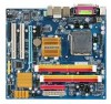
GA-G31MF-S2 Motherboard Layout KB_MS ATX_12V LGA775 CPU_FAN COMA LPT VGA USB_1394 USB_LAN AUDIO F_AUDIO PCIE_1 RTL8111C PCIE_16 IT8718 PCI1 CODEC PCI2 SPDIF_O CD_IN FDD Intel® G31 ATX IDE GA-G31MF-S2 DDRII1 DDRII2 DDRII3 DDRII4 BAT MBIOS CLR_CMOS F1_1394 SYS_FAN TSB43AB23 - Gigabyte GA-G31MF-S2 | Manual - Page 8
RTL8111C PCI Express Bus PCI Bus TSB43AB23 2 IEEE 1394a LGA775 Processor Host Interface Intel® G31 CPU CLK+/(333/266/200 MHz) DDR2 800/667 MHz Dual Channel Memory GMCH CLK (333/266/200 MHz) Intel® ICH7 CODEC BIOS ATA-100/66/33 IDE Channel 4 SATA 3Gb/s 8 USB Ports IT8718 Floppy LPT Port COM - Gigabyte GA-G31MF-S2 | Manual - Page 9
's manual and follow these procedures: • Prior to installation, do not remove or break motherboard S/N wrist strap when handling electronic components such as a motherboard, CPU or memory. If you do not have an ESD wrist steps or have a problem related to the use of the product, please consult - Gigabyte GA-G31MF-S2 | Manual - Page 10
775 package (Go to GIGABYTE's website for the latest CPU support list.) Š L2 cache varies with CPU Š 1333/1066/800 MHz FSB Š North Bridge: Intel® G31 Express Chipset Š South Bridge: Intel® ICH7 Š 4 x 1.8V DDR2 DIMM sockets supporting to the internal USB headers) GA-G31MF-S2 Motherboard - 10 - - Gigabyte GA-G31MF-S2 | Manual - Page 11
Internal Connectors Š 1 x 24-pin ATX main power connector Š 1 x 4-pin ATX 12V power connector Š 1 x floppy disk drive connector Š 1 x IDE connector Š 4 x SATA 3Gb/s connectors Š 1 x CPU fan header Š 1 x system fan header Š 1 x front panel header Š 1 x front panel audio header Š 1 x CD In - Gigabyte GA-G31MF-S2 | Manual - Page 12
physical memory is installed, the actual memory size displayed will be less than 4 GB. (Note 2) Whether the CPU fan speed control function is supported will depend on the CPU cooler you install. (Note 3) Available functions in Easytune may differ by motherboard model. GA-G31MF-S2 Motherboard - 12 - Gigabyte GA-G31MF-S2 | Manual - Page 13
do so according to your hardware specifications including the CPU, graphics card, memory, hard drive, etc. 1-3-1 Installing the CPU A. Locate the alignment keys on the motherboard CPU socket and the notches on the CPU. LGA775 CPU Socket Alignment Key LGA 775 CPU Alignment Key Pin One Corner of the - Gigabyte GA-G31MF-S2 | Manual - Page 14
pin one corner of the CPU socket (or you may align the CPU notches with the socket alignment keys) and gently insert the CPU into position. Step 5: Once the CPU is properly inserted, replace the load plate and push the CPU socket lever back into its locked position. GA-G31MF-S2 Motherboard - 14 - - Gigabyte GA-G31MF-S2 | Manual - Page 15
. Check that the Male and Female push pins are joined closely. (Refer to your CPU cooler installation manual for instructions on installing the cooler.) Step 5: After the installation, check the back of the motherboard. If the push pin is inserted as the picture above, the installation is complete - Gigabyte GA-G31MF-S2 | Manual - Page 16
installed, a message which says memory is operating in Flex Memory Mode will appear during the POST. Intel® Flex Memory Technology offers greater flexibility to upgrade by allowing different memory sizes to be populated and remain in Dual Channel mode/performance. GA-G31MF-S2 Motherboard - 16 - - Gigabyte GA-G31MF-S2 | Manual - Page 17
to install DDR2 DIMMs on this motherboard. Notch DDR2 DIMM A DDR2 memory module has a notch, so it can only fit in one direction. Follow the steps below to correctly install your memory modules in the memory sockets. Step 1: Note the orientation of the memory module. Spread the retaining clips at - Gigabyte GA-G31MF-S2 | Manual - Page 18
expansion card: • Make sure the motherboard supports the expansion card. Carefully read the manual that came with your expansion card. necessary, go to BIOS Setup to make any required BIOS changes for your expansion card(s). 7. Install the driver provided with the GA-G31MF-S2 Motherboard - 18 - - Gigabyte GA-G31MF-S2 | Manual - Page 19
Use this port for an IEEE 1394a device. USB Port The USB port supports the USB 2.0/1.1 specification. Use this port for USB devices such as an , first remove the cable from your device and then remove it from the motherboard. • When removing the cable, pull it straight out from the connector. - Gigabyte GA-G31MF-S2 | Manual - Page 20
speakers in a 4/5.1-channel audio configuration. Mic In Jack (Pink) The default Mic in jack. Microphones must be connected to this jack. Refer to the instructions on setting up a 2/4/5.1-channel audio configuration in Chapter 5, "Configuring 2/4/5.1-Channel Audio." GA-G31MF-S2 Motherboard - 20 - - Gigabyte GA-G31MF-S2 | Manual - Page 21
1-7 Internal Connectors 3 1 6 2 11 9 17 12 1) ATX_12V 2) ATX 3) CPU_FAN 4) SYS_FAN 5) FDD 6) IDE 7) SATAII0/1/2/3 8) PWR_LED 9) BAT 7 16 13 5 4 15 14 8 10 10) F_PANEL 11 make sure the device cable has been securely attached to the connector on the motherboard. - 21 - Hardware Installation - Gigabyte GA-G31MF-S2 | Manual - Page 22
connector mainly supplies power to the CPU. If motherboard. Do not insert the power supply cable into pins under the protective cover when using a 2x10 power supply. 3 4 1 2 ATX_12V ATX_12V : Pin No. 1 2 3 4 Definition GND GND +12V +12V 12 24 1 13 ATX ATX GA-G31MF-S2 Motherboard - 22 - - Gigabyte GA-G31MF-S2 | Manual - Page 23
wire indicates a positive connection and requires a +12V voltage. The black connector wire is the ground wire. The motherboard supports CPU fan speed control, which requires the use of a CPU fan with fan speed control design. For optimum heat dissipation, it is recommended that a system fan be - Gigabyte GA-G31MF-S2 | Manual - Page 24
master/slave settings for the IDE devices, read the instructions from the device manufacturers.) 1 2 39 40 7) supports a single SATA device. SATAII3 7 1 SATAII2 7 1 SATAII1 7 1 SATAII0 7 1 Pin No. 1 2 3 4 5 6 7 Definition GND TXP TXN GND RXN RXP GND GA-G31MF-S2 Motherboard - Gigabyte GA-G31MF-S2 | Manual - Page 25
+ MPDMPD- 1 System Status LED S0 On S1 Blinking S3/S4/S5 Off 9) BAT (BATTERY) The battery provides power to keep the values (such as BIOS configurations, date, and time information) in the CMOS when the computer is turned off. Replace the battery when the battery voltage drops to a low level - Gigabyte GA-G31MF-S2 | Manual - Page 26
. A front panel module mainly consists of power switch, reset switch, power LED, hard drive activity LED, speaker and etc. When connecting your chassis front panel module to this header, make sure the wire assignments and the pin assignments are matched correctly. GA-G31MF-S2 Motherboard - 26 - - Gigabyte GA-G31MF-S2 | Manual - Page 27
the pin assignments of the motherboard header. Incorrect connection between the module connector and the motherboard header will make the device unable panel audio header supports HD audio by default. If your chassis provides an AC'97 front panel audio module, refer to the instructions on how to - Gigabyte GA-G31MF-S2 | Manual - Page 28
S/PDIF out. Via an optional S/PDIF out cable, this header can connect to an audio device that supports digital audio in. For purchasing the optional S/PDIF out cable, please contact the local dealer. Pin No. the power outlet to prevent damage to the USB bracket. GA-G31MF-S2 Motherboard - 28 - - Gigabyte GA-G31MF-S2 | Manual - Page 29
end of the cable to the IEEE 1394a device. Ensure that the cable is securely connected. 16) CI (Chassis Intrusion Header) This motherboard provides a chassis detection feature that detects if the chassis cover has been removed. This function requires a chassis with chassis intrusion detection design - Gigabyte GA-G31MF-S2 | Manual - Page 30
the jumper. Failure to do so may cause damage to the motherboard. • After system restart, go to BIOS Setup to load factory defaults (select Load Optimized Defaults) or manually configure the BIOS settings (refer to Chapter 2, "BIOS Setup," for BIOS configurations). GA-G31MF-S2 Motherboard - 30 - - Gigabyte GA-G31MF-S2 | Manual - Page 31
that searches and downloads the latest version of BIOS from the Internet and updates the BIOS. For instructions on using the Q-Flash and @BIOS utilities, refer to Chapter 4, "BIOS Update Utilities." • Because BIOS flashing is potentially risky, if you do not encounter problems using the current - Gigabyte GA-G31MF-S2 | Manual - Page 32
, the device boot order will still be based on BIOS Setup settings. You can access Boot Menu again to change the first boot device setting as needed. : Q-Flash Press the key to access the Q-Flash utility directly without having to enter BIOS Setup first. GA-G31MF-S2 Motherboard - 32 - - Gigabyte GA-G31MF-S2 | Manual - Page 33
Access the Q-Flash utility Display system information Save all the changes and exit the BIOS Setup program Save CMOS to BIOS Load CMOS from BIOS Main Menu Help The onscreen description of a highlighted setup option is displayed on the bottom line of the - Gigabyte GA-G31MF-S2 | Manual - Page 34
your CPU, memory, etc BIOS Setup. (Pressing can also carry out this task.) „ Exit Without Saving Abandon all changes and the previous settings remain in effect. Pressing to the confirmation message will exit BIOS Setup. (Pressing can also carry out this task.) GA-G31MF-S2 Motherboard - Gigabyte GA-G31MF-S2 | Manual - Page 35
Drive A Floppy 3 Mode Support [1.44M, 3.5"] [Disabled] Halt On [All, But Keyboard] Base Memory Extended Memory Total Memory 640K 510M 512M KLJI: Move of the three methods below: • Auto • None • Manual Access Mode Lets BIOS automatically detect IDE/SATA devices during the POST. (Default) - Gigabyte GA-G31MF-S2 | Manual - Page 36
the parameters manually, refer to BIOS POST. Base Memory Also called conventional memory. Typically, 640 KB will be reserved for the MS-DOS operating system. Extended Memory The amount of extended memory. Total Memory The total amount of memory installed on the system. GA-G31MF-S2 Motherboard - Gigabyte GA-G31MF-S2 | Manual - Page 37
Advanced BIOS Features ` Hard Disk Boot Priority First Boot Device [Press Enter] [Floppy] Item Help Menu Level` Second Boot Device Third Boot Device Password Check [Hard Disk] [CDROM] [Setup] HDD S.M.A.R.T. Capability Limit CPUID Max. to 3 (Note) No-Execute Memory Protect (Note) CPU Enhanced - Gigabyte GA-G31MF-S2 | Manual - Page 38
use only this memory for display. Options are: 8MB+1~2MB for GTT (default), 1MB+1~2MB for GTT. (Note) This item is present only if you install a CPU that supports this feature. For more information about Intel CPUs' unique features, please visit Intel's website. GA-G31MF-S2 Motherboard - 38 - - Gigabyte GA-G31MF-S2 | Manual - Page 39
to USB Controller USB 2.0 Controller USB Keyboard Support USB Mouse Support Legacy USB storage detect Azalia Codec Onboard H/W SATA controller. Auto Lets BIOS set SATA devices to Combined automatically configured to Combined mode, you can manually re-configure it to Enhanced mode as needed - Gigabyte GA-G31MF-S2 | Manual - Page 40
This motherboard incorporates cable diagnostic feature designed to detect the status of the attached LAN cable. This feature will detect cabling issue and report the approximate distance to the fault or short. Refer to the following information for diagnosing your LAN cable: GA-G31MF-S2 Motherboard - Gigabyte GA-G31MF-S2 | Manual - Page 41
the motherboard, the Status fields of all four pairs of wires will show Open and the Length fields show 0m, as shown in the figure above. When LAN Cable Is Functioning Normally... If no cable problem is ), EPP (Enhanced Parallel Port), ECP (Extended Capabilities Port), ECP+EPP. - 41 - BIOS Setup - Gigabyte GA-G31MF-S2 | Manual - Page 42
from a PCI or PCIe device. Note: To use this function, you need an ATX power supply providing at least 1A on the +5VSB lead. (Default: Enabled) a modem that supports wake-up function. (Default: Enabled) (Note) Supported on Windows® Vista® operating system only. GA-G31MF-S2 Motherboard - 42 - - Gigabyte GA-G31MF-S2 | Manual - Page 43
may not be effective. HPET Support (Note) Enables or disables High To use this function, you need an ATX power supply providing at least 1A on the wake-up event. Note: you need an ATX power supply providing at least 1A on the AC power. (Default) Full-On Memory The system is turned on upon - Gigabyte GA-G31MF-S2 | Manual - Page 44
Help F7: Optimized Defaults BIOS auto-assigns IRQ to the first PCI slot. (Default) Assigns IRQ 3,4,5,7,9,10,11,12,14,15 to the first PCI slot. BIOS auto-assigns IRQ to the second PCI slot. (Default) Assigns IRQ 3,4,5,7,9,10,11,12,14,15 to the second PCI slot. GA-G31MF-S2 Motherboard - 44 - - Gigabyte GA-G31MF-S2 | Manual - Page 45
device attached to the motherboard CI header. If the CPU Temperature Displays current CPU temperature. Current CPU/SYSTEM FAN Speed (RPM) Displays current CPU/system fan speed. CPU Warning Temperature Sets the warning threshold for CPU temperature. When CPU temperature exceeds the threshold, BIOS - Gigabyte GA-G31MF-S2 | Manual - Page 46
fails to boot after overclocking, please wait for 20 seconds to allow for automated system reboot, or clear the CMOS values to reset the board to default values. (Default: Disabled) (Note) This item appears only if you install a CPU that supports this feature. GA-G31MF-S2 Motherboard - 46 - - Gigabyte GA-G31MF-S2 | Manual - Page 47
that is automatically adjusted according to the CPU Host Frequency (Mhz) and System Memory Multiplier settings. ******** System Voltage Optimized ******** System Voltage Control Determines whether to manually set the system voltages. Auto lets BIOS automatically set the system voltages as required - Gigabyte GA-G31MF-S2 | Manual - Page 48
Press on this item and then press the key to load the optimal BIOS default settings. The BIOS defaults settings helps the system to operate in optimum state. Always load the Optimized defaults after updating the BIOS or after clearing the CMOS values. GA-G31MF-S2 Motherboard - 48 - - Gigabyte GA-G31MF-S2 | Manual - Page 49
changes. When the Password Check item is set to System, you must enter the supervisor password (or user password) at system startup and when entering BIOS Setup. User Password When the Password Check item is set to System, you must enter the supervisor password (or user password) at system startup - Gigabyte GA-G31MF-S2 | Manual - Page 50
Setup F11: Save CMOS to BIOS F12: Load CMOS from BIOS Abandon all Data Press on this item and press the key. This exits the BIOS Setup without saving the changes made in BIOS Setup to the CMOS. Press or to return to the BIOS Setup Main Menu. GA-G31MF-S2 Motherboard - 50 - - Gigabyte GA-G31MF-S2 | Manual - Page 51
other drivers. • After the drivers are installed, follow the onscreen instructions to restart your system. You can install other applications included in the motherboard driver disk. • For USB 2.0 driver support under the Windows XP operating system, please install the Windows XP Service Pack - Gigabyte GA-G31MF-S2 | Manual - Page 52
all the tools and applications that GIGABYTE develops and some free software. You may press the Install button following an item to install it. 3-3 Driver CD Information This page provides information about the drivers, applications and tools in this driver disk. GA-G31MF-S2 Motherboard - 52 - - Gigabyte GA-G31MF-S2 | Manual - Page 53
3-4 Hardware Information This page provides information about the hardware devices on this motherboard. 3-5 Contact Us Check the contacts information of the GIGABYTE headquarter in Taiwan and the overseas branch offices on the last page of this manual. - 53 - Drivers Installation - Gigabyte GA-G31MF-S2 | Manual - Page 54
GA-G31MF-S2 Motherboard - 54 - - Gigabyte GA-G31MF-S2 | Manual - Page 55
It is recommended to back up your system soon after the operating system and drivers are installed. • The amount of data and hard drive access speed may affect . • USB hard drives are not supported. • Hard drives in RAID/AHCI mode are not supported. "*" Xpress Recovery2 checks the first physical - Gigabyte GA-G31MF-S2 | Manual - Page 56
Drive 1. Set CD-ROM drive as the first boot device under "Advanced BIOS Features" in the BIOS Setup program. Save the changes and exit. 2. When partitioning your hard drive for example, NTFS) and begin the installation of the operating system (Figure 3). Figure 3 GA-G31MF-S2 Motherboard - 56 - - Gigabyte GA-G31MF-S2 | Manual - Page 57
4. After the operating system is installed, right-click the My Computer icon on your desktop and select Manage (Figure 4). Go to Computer Management to check disk allocation. Xpress Recovery2 will save the backup file to the unallocated space (black stripe along the top)(Figure 5). Please note that - Gigabyte GA-G31MF-S2 | Manual - Page 58
from the motherboard driver disk to Award Modular BIOS v6.00PG, An Energy Star Ally Copyright (C) 1984-2007, Award Software, Inc. G31MF-S2 E10 . . . . : BIOS Setup/Q-Flash to check disk allocation. Figure 12 GA-G31MF-S2 Motherboard Xpress Recovery2 will automatically create a new partition to - Gigabyte GA-G31MF-S2 | Manual - Page 59
D. Using the Restore Function in Xpress Recovery2 Select RESTORE to restore the backup to your hard drive in case the system breaks down. The RESTORE option will not be present if no backup is created before (Figure 13, 14). Figure 13 Figure 14 E. Removing the Backup 1. If you wish to remove the - Gigabyte GA-G31MF-S2 | Manual - Page 60
nearest @BIOS server site and update the BIOS. 4-2-1 Updating the BIOS with the Q-Flash Utility A. Before You Begin: 1. From GIGABYTE's website, download the latest compressed BIOS update file that matches your motherboard model. 2. Extract the file and save the new BIOS file (e.g. G31MFS2.F1) to - Gigabyte GA-G31MF-S2 | Manual - Page 61
key to select Update BIOS from Drive and press . • The Save Main BIOS to Drive option allows you to save the current BIOS file. • Q-Flash only supports USB flash drive or hard drives using FAT32/16/12 file system. • If the BIOS update file is saved to a hard drive in RAID/AHCI mode or a hard - Gigabyte GA-G31MF-S2 | Manual - Page 62
Setup F11: Save CMOS to BIOS F12: Load CMOS from BIOS Load Optimized Defaults Press to load BIOS defaults Step 6: Select Save & Exit Setup and then press to save settings to CMOS and exit BIOS Setup. The procedure is complete after the system restarts. GA-G31MF-S2 Motherboard - 62 - - Gigabyte GA-G31MF-S2 | Manual - Page 63
@BIOS: Use the motherboard driver disk included with the motherboard to install @BIOS. • Installing the @BIOS utility. • Accessing the @BIOS utility. Select @BIOS and click Install. Click Start>All Programs>GIGABYTE>@BIOS C. Options and Instructions: 1. Save the Current BIOS File In the main - Gigabyte GA-G31MF-S2 | Manual - Page 64
in an unbootable system. • If the BIOS update file for your motherboard is not present on the @BIOS server site, please manually download the BIOS update file from GIGABYTE's website and follow the instructions in "Update the BIOS without Using the Internet Update Function" below. Step 4: As the - Gigabyte GA-G31MF-S2 | Manual - Page 65
BIOS Setup program. EasyTune 5 Pro provides the following functions (Note 1): overclocking/overvoltage, C.I.A./M.I.B. (Note 2), smart fan control, and hardware monitoring and warning. (For instructions on using EasyTune5 Pro, read or download the information on/from the Support\Motherboard\Utility - Gigabyte GA-G31MF-S2 | Manual - Page 66
this device. Under Space to reserve for system speed, set the amount of memory space to use for ReadyBoost using the slider or spin box. Click Apply of memory to use for ReadyBoost acceleration is one to three times the amount of RAM installed in your computer. GA-G31MF-S2 Motherboard - 66 - - Gigabyte GA-G31MF-S2 | Manual - Page 67
Front Speaker Out Mic In If your front panel audio supports Intel HD Audio standard, you can have both the driver, make sure the "Microsoft UAA Bus driver for High Definition Audio" has been installed from the motherboard driver disk and your operating system has been updated with the latest Service - Gigabyte GA-G31MF-S2 | Manual - Page 68
according to the type of device you connect. Then click OK to complete the configuration. Front Speaker Out Rear Speaker Out Center/Subwoofer Speaker Out GA-G31MF-S2 Motherboard - 68 - - Gigabyte GA-G31MF-S2 | Manual - Page 69
B. Configuring Sound Effect: You may configure an audio environment on the Sound Effect tab. C. Configuring AC'97 Audio: If you want to connect an AC'97 front panel audio module, click the tool icon on the Audio I/O tab On the Global Connector Settings box, select the Disable front panel jack - Gigabyte GA-G31MF-S2 | Manual - Page 70
on your motherboard. Pin 1 (the red wire) of the S/PDIF out cable must align with pin 1 of the SPDIF_O header. Incorrect connection may render the device unusable or even result in damage to the device. Step 2: Secure the metal bracket to the chassis back panel with a screw. GA-G31MF-S2 Motherboard - Gigabyte GA-G31MF-S2 | Manual - Page 71
S/PDIF Coaxial Cable Step 3: Connect a S/PDIF coaxial cable or a S/PDIF optical cable (either one) to an external decoder for transmitting the S/PDIF digital audio signals. S/PDIF Optical Cable B. Configuring S/PDIF out: Click the tool icon in the DIGITAL section. In the S/PDIF Settings dialog box - Gigabyte GA-G31MF-S2 | Manual - Page 72
5-1-3 Configuring Microphone Recording Step 1: After installing the audio driver, the Audio Manager icon will appear in your system tray. Doubleclick the icon to access the Audio Locate the Volume icon in your system tray and click it to open the volume control panel. GA-G31MF-S2 Motherboard - 72 - - Gigabyte GA-G31MF-S2 | Manual - Page 73
Step 4: To hear the sound being recorded during the record- ing process when using the microphone function on or the front panel, do not select the Mute check box under Front Pink In or Front Green In in Master Volume. It is recommended that you set the volume at a middle level. To hear the - Gigabyte GA-G31MF-S2 | Manual - Page 74
the Stop button . 5. You may use the Fast Forward button to move to the beginning of a file or the Fast Backward button to the end. GA-G31MF-S2 Motherboard - 74 - - Gigabyte GA-G31MF-S2 | Manual - Page 75
5-2 Troubleshooting 5-2-1 Frequently Asked Questions To read more FAQs for your motherboard, please go to the Support\Motherboard\FAQ page on GIGABYTE's website. Q: In the BIOS Setup program, why are some BIOS options missing? A: Some advanced options are hidden in the BIOS Setup program. Press < - Gigabyte GA-G31MF-S2 | Manual - Page 76
insert the memory into the memory socket. The problem is verified and solved. Press to enter BIOS Setup. Select "Load Fail-Safe Defaults" (or "Load Optimized Defaults"). Select "Save & Exit Setup" to save changes and exit BIOS Setup. A (Continued...) GA-G31MF-S2 Motherboard - 76 - Gigabyte GA-G31MF-S2 | Manual - Page 77
CPU socket might fail. The problem is verified and solved. No The graphics card, expansion slot, or monitor might fail. The problem is verified and solved. Check if the keyboard is working properly. Yes Press to enter BIOS Setup. Select "Load Fail-Safe Defaults" (or "Load Optimized - Gigabyte GA-G31MF-S2 | Manual - Page 78
product. Restriction of Hazardous Substances (RoHS) Directive Statement GIGABYTE products have not intended to add and safe from office, your household waste disposal service or where you purchased the manual and we will be glad to help you with your effort. GA-G31MF-S2 Motherboard - 78 - - Gigabyte GA-G31MF-S2 | Manual - Page 79
Finally, we suggest that you practice other environmentally friendly actions by understanding and using the energy-saving features of this product (where applicable), recycling the inner and outer packaging (including shipping containers) this product was delivered in, and by disposing of or - Gigabyte GA-G31MF-S2 | Manual - Page 80
GA-G31MF-S2 Motherboard - 80 - - Gigabyte GA-G31MF-S2 | Manual - Page 81
- 81 - Appendix - Gigabyte GA-G31MF-S2 | Manual - Page 82
GA-G31MF-S2 Motherboard - 82 - - Gigabyte GA-G31MF-S2 | Manual - Page 83
) FAX: +1-626-854-9339 Correo: [email protected] Tech. Support: http://rma.gigabyte-usa.com Web address: http://www.gigabyte.com.mx Singapore GIGA-BYTE SINGAPORE PTE. LTD. WEB address : http://www.gigabyte.sg Thailand WEB address : http://th.giga-byte.com Vietnam WEB address : http://www - Gigabyte GA-G31MF-S2 | Manual - Page 84
your language in the language list on the top right corner of the website. GIGABYTE Global Service System To submit a technical or non-technical (Sales/ Marketing) question, please link to : http://ggts.gigabyte.com.tw Then select your language to enter the system. GA-G31MF-S2 Motherboard - 84 -
-
 1
1 -
 2
2 -
 3
3 -
 4
4 -
 5
5 -
 6
6 -
 7
7 -
8
-
9
-
10
-
11
-
12
-
13
-
14
-
15
-
16
-
17
-
18
-
19
-
20
-
21
-
22
-
23
-
24
-
25
-
26
-
27
-
28
-
29
-
30
-
31
-
32
-
33
-
34
-
35
-
36
-
37
-
38
-
39
-
40
-
41
-
42
-
43
-
44
-
45
-
46
-
47
-
48
-
49
-
50
-
51
-
52
-
53
-
54
-
55
-
56
-
57
-
58
-
59
-
60
-
61
-
62
-
63
-
64
-
65
-
66
-
67
-
68
-
69
-
70
-
71
-
72
-
73
-
74
-
75
-
76
-
77
-
78
-
79
-
80
-
81
-
82
-
83
-
84
 |
 |

GA-G31MF-S2
LGA775 socket motherboard for Intel
®
Core
TM
processor family/
Intel
®
Pentium
®
processor family/Intel
®
Celeron
®
processor family
User's Manual
Rev. 1001
12ME-G31MFS2-1001R