Gigabyte GA-P55-UD3P Manual
Gigabyte GA-P55-UD3P Manual
 |
View all Gigabyte GA-P55-UD3P manuals
Add to My Manuals
Save this manual to your list of manuals |
Gigabyte GA-P55-UD3P manual content summary:
- Gigabyte GA-P55-UD3P | Manual - Page 1
GA-P55-UD3P GA-P55-UD3R LGA1156 socket motherboard for Intel® Core™ i7 processor family/ Intel® Core™ i5 processor family User's Manual Rev. 1001 12ME-P55UD3P-1001R - Gigabyte GA-P55-UD3P | Manual - Page 2
Motherboard GA-P55-UD3P/GA-P55-UD3R Jul. 14, 2009 Motherboard GA-P55-UD3P / GA-P55-UD3R Jul. 14, 2009 - Gigabyte GA-P55-UD3P | Manual - Page 3
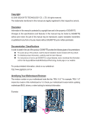
with the product. For detailed product information, carefully read the User's Manual. For instructions on how to use GIGABYTE's unique features, read or download the information on/from the Support&Downloads\Motherboard\Technology Guide page on our website. For product-related information, check on - Gigabyte GA-P55-UD3P | Manual - Page 4
...6 GA-P55-UD3P/GA-P55-UD3R Motherboard Layout 7 Block Diagram...8 Chapter 1 Hardware Installation 9 1-1 Installation Precautions 9 1-2 Product Specifications 10 1-3 Installing the CPU and CPU Cooler 13 1-3-1 Installing the CPU 13 1-3-2 Installing the CPU Cooler 15 1-4 Installing the Memory - Gigabyte GA-P55-UD3P | Manual - Page 5
TPM j 81 Chapter 5 Appendix...83 5-1 Configuring SATA Hard Drive(s 83 5-1-1 Configuring Intel P55 SATA Controllers 83 5-1-2 Configuring JMB362/GIGABYTE SATA2 SATA Controller 91 5-1-3 Making a SATA RAID/AHCI Driver Diskette 97 5-1-4 Installing the SATA RAID/AHCI Driver and Operating System 98 - Gigabyte GA-P55-UD3P | Manual - Page 6
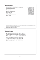
Box Contents GA-P55-UD3P or GA-P55-UD3R motherboard Motherboard driver disk User's Manual Quick Installation Guide One IDE cable Four SATA 3Gb/s 2-port USB 2.0 bracket (Part No. 12CR1-1UB030-5*R) 2-port SATA power cable (Part No. 12CF1-2SERPW-0*R) S/PDIF In cable (Part No. 12CR1-1SPDIN-0*R) COM port - Gigabyte GA-P55-UD3P | Manual - Page 7
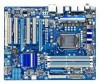
GA-P55-UD3P/GA-P55-UD3R Motherboard Layout KB_USB R_SPDIF CPU_FAN ATX_12V_2X4 USB_ESATA_2 USB_ESATA_1 LGA1156 PHASE LED ATX PWR_FAN GA-P55-UD3P / GA-P55-UD3R R_USB USB_LAN JMB362 SYS_FAN1 AUDIO F_AUDIO RTL8111D PCIEX16 PCIEX1(Note) PCI1 CODEC PCI2 PCIEX4 TPM IC j DDR3_2 DDR3_1 - Gigabyte GA-P55-UD3P | Manual - Page 8
P55 x4 PCI Express Bus x1 2 SATA 3Gb/s Dual BIOS JMB362 6 SATA 3Gb/s 14 USB Ports CODEC LPC Bus IT8720 Floppy COM Port PS/2 KB/Mouse TPM j Surround Speaker Out Center/Subwoofer Speaker Out Side Speaker Out MIC Line Out Line In S/PDIF In S/PDIF Out 4 PCI PCI CLK (33 MHz) j Only for GA-P55 - Gigabyte GA-P55-UD3P | Manual - Page 9
user's manual and follow these procedures: • Prior to installation, do not remove or break motherboard ) wrist strap when handling electronic com- ponents such as a motherboard, CPU or memory. If you do not have the user. • If you are uncertain about any installation steps or have a problem related - Gigabyte GA-P55-UD3P | Manual - Page 10
Intel® P55 Express Chipset: - 6 x SATA 3Gb/s connectors (SATA2_0, SATA2_1, SATA2_2, SATA2_3, SATA2_4, SATA2_5) supporting up to 6 SATA 3Gb/s devices - Support for SATA RAID 0, RAID 1, RAID 5, and RAID 10 GIGABYTE SATA2 chip: - 1 x IDE connector supporting ATA - Gigabyte GA-P55-UD3P | Manual - Page 11
in the Chipset Up to 14 USB 2.0/1.1 ports (10 on the back panel, 4 via the USB brackets connected to the internal USB headers) 1 x 24-pin ATX main power connector 1 x 8-pin ATX 12V power connector 1 x floppy disk drive connector 1 x IDE connector 8 x SATA 3Gb/s connectors 1 x CPU fan header - Gigabyte GA-P55-UD3P | Manual - Page 12
Operating System w Support for Microsoft® Windows® 7/Vista/XP Form Factor w ATX Form Factor; 30.5cm x 24.4cm j Only for GA-P55-UD3P. (Note 1) Due to Windows Vista/XP 32-bit operating system limitation, when more than 4 GB of physical memory is installed, the actual memory size displayed will - Gigabyte GA-P55-UD3P | Manual - Page 13
the CPU: • Make sure that the motherboard supports the CPU. (Go to GIGABYTE's website for the latest CPU support list.) • Always turn off the computer memory, hard drive, etc. 1-3-1 Installing the CPU A. Locate the alignment keys on the motherboard CPU socket and the notches on the CPU. LGA1156 - Gigabyte GA-P55-UD3P | Manual - Page 14
B. Follow the steps below to correctly install the CPU into the motherboard CPU socket. Before installing the CPU, make sure to turn off the computer and unplug the power cord from the power outlet to prevent damage - Gigabyte GA-P55-UD3P | Manual - Page 15
below to correctly install the CPU cooler on the motherboard. (The following procedure uses Intel® boxed cooler as the example cooler.) Step 1: CPU cooler installation manual for instructions on installing the cooler.) Step 5: After the installation, check the back of the motherboard. If the push - Gigabyte GA-P55-UD3P | Manual - Page 16
following guidelines before you begin to install the memory: • Make sure that the motherboard supports the memory. It is recommended that memory of the same capacity, brand, speed, and chips be used. (Go to GIGABYTE's website for the latest memory support list.) • Always turn off the computer and - Gigabyte GA-P55-UD3P | Manual - Page 17
the power cord from the power outlet to prevent damage to the memory module. DDR3 and DDR2 DIMMs are not compatible to each other or DDR DIMMs. Be sure to install DDR3 DIMMs on this motherboard. Notch DDR3 DIMM A DDR3 memory module has a notch, so it can only fit in one direction. Follow - Gigabyte GA-P55-UD3P | Manual - Page 18
an expansion card: • Make sure the motherboard supports the expansion card. Carefully read the manual that came with your expansion card. • Always If necessary, go to BIOS Setup to make any required BIOS changes for your expansion card(s). 7. Install the driver provided with the expansion card - Gigabyte GA-P55-UD3P | Manual - Page 19
SATA Hard Drive(s)," for instructions on configuring a RAID array. RJ-45 LAN Port The Gigabit Ethernet LAN port provides Internet connection at up to 1 Gbps data rate. The following describes the states of the LAN port LEDs. Connection/ Speed LED Activity LED LAN Port Connection/Speed LED - Gigabyte GA-P55-UD3P | Manual - Page 20
to perform different functions via the audio software. Only microphones still MUST be connected to the default Mic in jack ( ). Refer to the instructions on setting up a 2/4/5.1/7.1-channel audio configuration in Chapter 5, "Configuring 2/4/5.1/7.1-Channel Audio." Hardware Installation - 20 - - Gigabyte GA-P55-UD3P | Manual - Page 21
7 9 13 4 14 8 15 19 11 18 17 6 10 16 1) ATX_12V_2X4 2) ATX 3) CPU_FAN 4) SYS_FAN1/2 5) PWR_FAN 6) FDD 7) IDE 8) SATA2_0/1/2/3/4/5 9) GSATA2_0/1 10) BAT 11) F_PANEL 12) F_AUDIO 13) CD_IN 14) SPDIF_I been securely attached to the connector on the motherboard. - 21 - Hardware Installation - Gigabyte GA-P55-UD3P | Manual - Page 22
by the CPU manufacturer when using an Intel Extreme Edition CPU (130W). • To and the main power connector on the motherboard. Do not insert the power supply 12V) 7 +12V 8 +12V 12 24 1 13 ATX Hardware Installation ATX: Pin No. 1 2 3 4 5 6 7 8 9 10 11 12 Definition Pin No. 3.3V 13 3.3V 14 - Gigabyte GA-P55-UD3P | Manual - Page 23
design. When connecting a fan cable, be sure to connect it in the correct orientation (the black connector wire is the ground wire). The motherboard supports CPU fan speed control, which requires the use of a CPU fan with fan speed control design. For optimum heat dissipation, it is recom - Gigabyte GA-P55-UD3P | Manual - Page 24
P55 Chipset, Blue) The SATA connectors conform to SATA 3Gb/s standard and are compatible with SATA 1.5Gb/s standard. Each SATA connector supports a single SATA device. The P55 Chipset supports RAID 0, RAID 1, RAID 5, and RAID 10. Refer to Chapter 5, "Configuring SATA Hard Drive(s)," for instructions - Gigabyte GA-P55-UD3P | Manual - Page 25
and are compatible with SATA 1.5Gb/s standard. Each SATA connector supports a single SATA device. The GIGABYTE SATA2 controller supports RAID 0, RAID 1, and JBOD. Refer to Chapter 5, "Configuring SATA Hard Drive(s)," for instructions on configuring a RAID array. GSATA2_1 7 1 7 1 GSATA2_0 Pin - Gigabyte GA-P55-UD3P | Manual - Page 26
beep will be heard if no problem is detected at system startup. If a problem is detected, the BIOS may issue beeps in different patterns to indicate the problem. Refer to Chapter 5, "Troubleshooting," for information about beep codes. • HD (Hard Drive Activity LED, Blue) Connects to the hard drive - Gigabyte GA-P55-UD3P | Manual - Page 27
GND 6 NC 7 FAUDIO_JD 7 NC 8 No Pin 8 No Pin 9 LINE2_L 9 Line Out (L) 10 GND 10 NC • The front panel audio header supports HD audio by default. If your chassis provides an AC'97 front panel audio module, refer to the instructions on how to activate AC'97 functionality via the audio software - Gigabyte GA-P55-UD3P | Manual - Page 28
) This header supports digital S/PDIF Out and connects a S/PDIF digital audio cable (provided by expansion cards) for digital audio output from your motherboard to certain expansion audio cable, carefully read the manual for your expansion card. Pin No. Definition 1 SPDIFO 2 GND 1 Hardware - Gigabyte GA-P55-UD3P | Manual - Page 29
local dealer. Pin No. Definition 1 Power (5V) 9 1 2 Power (5V) 10 2 3 USB DX- 4 USB DY- 5 USB DX+ 6 USB DY+ 7 GND 8 GND 9 No Pin 10 NC • Do not plug the IEEE 1394 bracket (2x5-pin) cable into the USB header. • Prior to installing the USB bracket, be sure to turn off your computer and - Gigabyte GA-P55-UD3P | Manual - Page 30
the jumper. Failure to do so may cause damage to the motherboard. • After system restart, go to BIOS Setup to load factory defaults (select Load Optimized Defaults) or manually configure the BIOS settings (refer to Chapter 2, "BIOS Setup," for BIOS configurations). Hardware Installation - 30 - - Gigabyte GA-P55-UD3P | Manual - Page 31
20) PHASE LED The number of lighted LEDs indicates the CPU loading. The higher the CPU loading, the more the number of lighted LEDs. To enable the Phase LED display function, please first enable Dynamic Energy Saver™ 2. Refer to Chapter 4, "Dynamic Energy Saver™ 2," for more details. - 31 - - Gigabyte GA-P55-UD3P | Manual - Page 32
Hardware Installation - 32 - - Gigabyte GA-P55-UD3P | Manual - Page 33
the GIGABYTE Q-Flash or @BIOS utility. • Q-Flash allows the user to quickly and easily upgrade or back up BIOS without entering the operating system. • @BIOS is a Windows-based utility that searches and downloads the latest version of BIOS from the Internet and updates the BIOS. For instructions on - Gigabyte GA-P55-UD3P | Manual - Page 34
v6.00PG, An Energy Star Ally Copyright (C) 1984-2009, Award Software, Inc. Motherboard Model BIOS Version P55-UD3P D6 . . . . : BIOS Setup : XpressRecovery2 : Boot Menu : Qflash 07/08/2009-P55-7A89RG0JC-00 Function Keys Function Keys Function Keys: : POST SCREEN Press - Gigabyte GA-P55-UD3P | Manual - Page 35
a sub-menu. (Sample BIOS Version: GA-P55-UD3P D6) CMOS Setup Utility- User Password Save & Exit Setup Exit Without Saving Security Chip Configuration j ESC: Quit F8: Q-Flash Select Item F10: Save & Exit Setup Change CPU's Clock & Voltage F11: Save CMOS to BIOS F12: Load CMOS from BIOS BIOS - Gigabyte GA-P55-UD3P | Manual - Page 36
. Advanced BIOS Features Use this menu to configure the device boot order, advanced features available on the CPU, and the primary display adapter. Integrated Peripherals Use this menu to configure all peripheral devices, such as IDE, SATA, USB, integrated audio, and integrated LAN, etc. Power - Gigabyte GA-P55-UD3P | Manual - Page 37
Defaults (Note 1) This item is present only if you install a CPU that supports this feature. For more information about Intel CPUs' unique features, please visit Intel's website. (Note 2) This item appears only if you install a memory module that supports this feature. - 37 - BIOS Setup - Gigabyte GA-P55-UD3P | Manual - Page 38
to decrease power consumption. Auto lets the BIOS automatically configure this setting. (Default: Auto) (Note) This item is present only if you install a CPU that supports this feature. For more information about Intel CPUs' unique features, please visit Intel's website. BIOS Setup - 38 - - Gigabyte GA-P55-UD3P | Manual - Page 39
is determined by multiplying the BLCK Frequency value by the Uncore Clock Ratio value. (Note) This item is present only if you install a CPU that supports this feature. For more information about Intel CPUs' unique features, please visit Intel's website. - 39 - BIOS Setup - Gigabyte GA-P55-UD3P | Manual - Page 40
Allows you to manually set the overclocking capability of your CPU. As stability is highly dependent on system components, when system instability occurs after overclocking, lower the overclocking ratio. (Note) This item appears only if you install a memory module that supports this feature. BIOS - Gigabyte GA-P55-UD3P | Manual - Page 41
operating frequency of the memory being used; the second is the memory frequency that is automatically adjusted according to the BCLK Frequency(Mhz) and System Memory Multiplier settings. (Note) This item appears only if you install a memory module that supports this feature. - 41 - BIOS Setup - Gigabyte GA-P55-UD3P | Manual - Page 42
display the value based on the SPD data on the XMP memory. Profile QPI Voltage The value displayed here is dependent on the Control x tRC 28 x tRRD 4 x tWTR 5 x tWR 10 x tWTP 21 x tWL 7 x tRFC 60 x tRTP 5 (default), 1~15. BIOS Setup - 42 - - Gigabyte GA-P55-UD3P | Manual - Page 43
Options are: Auto (default), 1~31. tWR Options are: Auto (default), 1~15. tWTP Options are: Auto (default), 1~31. tWL Options are: Auto (default), 1~10 tRFC Options are: Auto (default), 1~255. tRTP Options are: Auto (default), 1~15. tFAW Options are: Auto (default), 1~63. Command Rate(CMD) Options - Gigabyte GA-P55-UD3P | Manual - Page 44
are: Auto (default), 1~8. Different Ranks Options are: Auto (default), 1~8. On The Same Rank Options are: Auto (default), 1~2. ESC: Exit F1: General Help F7: Optimized Defaults BIOS Setup - 44 - - Gigabyte GA-P55-UD3P | Manual - Page 45
keeping the CPU voltage more constant under light and heavy CPU load. Disabled sets the CPU voltage following Intel specifications. (Default: Disabled) Note: Enabling Load-Line Calibration may result in damage to your CPU . The default is Auto. Ch-B Data VRef. The default is Auto. - 45 - BIOS Setup - Gigabyte GA-P55-UD3P | Manual - Page 46
ESC: Exit F1: General Help F7: Optimized Defaults Isochronous Support Determines whether to enable specific streams within the CPU and Chipset Enter] Item Help Menu Level BIOS Version BCLK CPU Frequency Memory Frequency Total Memory Size D6 133.27 MHz 3198.42 - Gigabyte GA-P55-UD3P | Manual - Page 47
1984-2009 Award Software Standard CMOS Features Base Memory Extended Memory Total Memory 640K 1022M 1024M Item Help Menu Level Move parameters of the IDE/SATA device on this channel. IDE Channel 0, 1 Master/Slave Configure your IDE/SATA devices by using one of the three methods - Gigabyte GA-P55-UD3P | Manual - Page 48
Lets the BIOS automatically detect IDE/SATA devices during the POST. (Default) • None If no IDE/SATA devices are used, set this item to None so the system will skip the detection of the device during the POST for faster system startup. • Manual Allows you to manually enter the - Gigabyte GA-P55-UD3P | Manual - Page 49
-FDD, USB-ZIP, USB-CDROM, USB-HDD, Legacy LAN, Disabled. Password Check Specifies whether a password is required every time the system boots, or only when you enter BIOS Setup. After configuring this item, set the password(s) under the Set Supervisor/User Password item in the BIOS Main Menu. Setup - Gigabyte GA-P55-UD3P | Manual - Page 50
operating system such as Windows NT4.0. (Default: Disabled) No-Execute Memory Protect (Note) Enables or disables Intel Execute Disable Bit function. install a CPU that supports this feature. For more information about Intel CPUs' unique features, please visit Intel's website. BIOS Setup - 50 - - Gigabyte GA-P55-UD3P | Manual - Page 51
Help F7: Optimized Defaults SATA RAID/AHCI Mode (Intel P55 Chipset) Enables or disables RAID for the SATA controllers integrated in the Intel P55 chipset or configures the SATA controllers to AHCI mode. Disabled Disables RAID for the SATA controllers and configures the SATA controllers to IDE - Gigabyte GA-P55-UD3P | Manual - Page 52
is attached to the motherboard, the Status fields of all four pairs of wires will show Open and the Length fields show 0m, as shown in the figure above. When LAN Cable Is Functioning Normally... If no cable problem is detected on the LAN cable connected to a Gigabit hub or a 10/100 Mbps hub, the - Gigabyte GA-P55-UD3P | Manual - Page 53
Note: Part 4-5 and Part 7-8 are not used in a 10/100 Mbps environment, so their Status fields will show Open, and the driver to enable advanced Serial ATA features such as Native Command Queuing and hot plug. RAID Enables RAID for the SATA controller. GSATA 0_1/IDE Controller (GIGABYTE - Gigabyte GA-P55-UD3P | Manual - Page 54
ATX power supply providing at least 1A on the +5VSB lead. (Default: Enabled) Power On by Ring Allows the system to be awakened from an ACPI sleep state by a wake-up signal from a modem that supports wake-up function. (Default: Enabled) (Note) Supported on Windows Vista operating system only. BIOS - Gigabyte GA-P55-UD3P | Manual - Page 55
when you install 64-bit Windows Vista. This item is configurable only if the HPET Support is set to Enabled. (Default: 32-bit mode) Power On By Mouse Allows the system to be turned on by a PS/2 mouse wake-up event. Note: To use this function, you need an ATX power supply providing at - Gigabyte GA-P55-UD3P | Manual - Page 56
Displays the detection status of the chassis intrusion detection device attached to the motherboard CI header. If the system chassis cover is removed, this field for CPU temperature. When CPU temperature exceeds the threshold, BIOS will emit warning sound. Options are: Disabled (default), 60oC - Gigabyte GA-P55-UD3P | Manual - Page 57
configurable only if CPU Smart FAN Control is set to Enabled. Auto Lets the BIOS automatically detect the type of CPU fan installed and sets the optimal CPU fan fan that is not designed following Intel PWM fan specifications, selecting PWM mode may not effectively reduce the fan speed. - 57 - Gigabyte GA-P55-UD3P | Manual - Page 58
BIOS Press on this item and then press the key to load the optimal BIOS default settings. The BIOS defaults settings help the system to operate in optimum state. Always load the Optimized defaults after updating the BIOS or after clearing the CMOS values. j Only for GA-P55-UD3P. BIOS - Gigabyte GA-P55-UD3P | Manual - Page 59
to view the BIOS settings but not to make changes. To clear the password, press on the password item and when requested for the password, press again. The message "PASSWORD DISABLED" will appear, indicating the password has been cancelled. j Only for GA-P55-UD3P. - 59 - BIOS Setup - Gigabyte GA-P55-UD3P | Manual - Page 60
Advanced BIOS Features Set User Password BIOS F12: Load CMOS from BIOS Press on this item and press the key. This exits the BIOS Setup without saving the changes made in BIOS Setup to the CMOS. Press or to return to the BIOS Setup Main Menu. j Only for GA-P55-UD3P. BIOS - Gigabyte GA-P55-UD3P | Manual - Page 61
this function with the Supervisor/ User password. Enabled/Activate Enables the security chip and initializes the Security Platform. Disabled Disables the security chip. (Default) Security Chip State Displays the current settings in the security chip. j Only for GA-P55-UD3P. - 61 - BIOS Setup - Gigabyte GA-P55-UD3P | Manual - Page 62
BIOS Setup - 62 - - Gigabyte GA-P55-UD3P | Manual - Page 63
recommended drivers. Or click Install Single Items to manually select the drivers instructions to restart your system. You can install other applications included in the motherboard driver disk. • For USB 2.0 driver support under the Windows XP operating system, please install the Windows XP Service - Gigabyte GA-P55-UD3P | Manual - Page 64
applications that GIGABYTE develops and some free software. You can click the Install button on the right of an item to install it. 3-3 Technical Manuals This page provides GIGABYTE's application guides, content descriptions for this driver disk, and the motherboard manuals. Drivers Installation - Gigabyte GA-P55-UD3P | Manual - Page 65
3-4 Contact For the detailed contact information of the GIGABYTE Taiwan headquarter or worldwide branch offices, click the URL on this page to link to the GIGABYTE website. 3-5 System This page provides the basic system information. - 65 - Drivers Installation - Gigabyte GA-P55-UD3P | Manual - Page 66
Center To update the BIOS, drivers, or applications, click the Download Center button to link to the GIGABYTE website. The latest version of the BIOS, drivers, or applications will be displayed. 3-7 New Utilities This page provides a quick link to GIGABYTE's lately developed utilities for users to - Gigabyte GA-P55-UD3P | Manual - Page 67
in advanced (10 GB or system and drivers are installed. USB hard drives are not supported. • Hard drives in RAID/AHCI mode are not supported. Installation and Configuration: Turn on your system to boot from the Windows Vista setup disk. A. Installing Windows SATA connector, the second SATA connector - Gigabyte GA-P55-UD3P | Manual - Page 68
your hard drive, make sure to leave unallocated space (10 GB or more is recommended; actual size requirements vary, Recovery2 cannot save the backup file. B. Accessing Xpress Recovery2 1. Boot from the motherboard driver disk to access Xpress Recovery2 for the first time. When you see the - Gigabyte GA-P55-UD3P | Manual - Page 69
D. Using the Restore Function in Xpress Recovery2 Select RESTORE to restore the backup to your hard drive in case the system breaks down. The RESTORE option will not be present if no backup is created before. E. Removing the Backup Step 1: If you wish to remove the backup file, select REMOVE. Step - Gigabyte GA-P55-UD3P | Manual - Page 70
system BIOS while in the Windows environment. @BIOS will download the latest BIOS file from the nearest @BIOS server 4-2-1 Updating the BIOS with the Q-Flash Utility A. Before You Begin 1. From GIGABYTE's website, download the latest compressed BIOS update file that matches your motherboard model - Gigabyte GA-P55-UD3P | Manual - Page 71
option allows you to save the current BIOS file. • Q-Flash only supports USB flash drive or hard drives using FAT32/16/12 file system. • If the BIOS update file is saved to a hard drive in RAID/AHCI mode or a hard drive attached to an independent IDE/SATA controller, use the key during the - Gigabyte GA-P55-UD3P | Manual - Page 72
devices after a BIOS update, so we recommend that you reload BIOS defaults. CMOS Setup Utility-Copyright (C) 1984-2009 Award Software MB Intelligent Tweaker(M.I.T.) Load Optimized Defaults Standard CMOS Features Set Supervisor Password Advanced BIOS Features Set User Password - Gigabyte GA-P55-UD3P | Manual - Page 73
. If the BIOS update file for your motherboard is not present on the @BIOS server site, please manually download the BIOS update file from GIGABYTE's website and follow the instructions in "Update the BIOS without Using the Internet Update Function" below. 2. Update the BIOS without Using the - Gigabyte GA-P55-UD3P | Manual - Page 74
EasyTune 6 GIGABYTE's EasyTune 6 is a simple and easy-to-use interface that allows users to fine-tune their system settings or do overclock/overvoltage in Windows environment. The user-friendly EasyTune 6 interface also includes tabbed pages for CPU and memory information, letting users read their - Gigabyte GA-P55-UD3P | Manual - Page 75
, GIGABYTE Dynamic 10 3-Level Power Saving Switch (Default:1) (Note 2) 11 Advanced Settings 12 Close (Application will enter Stealth Mode) 13 Minimize (Application will continue to run in taskbar) 14 INFO/Help 15 Motherboard Phase LED On/Off Switch (Default: On) 16 Live Utility Update - Gigabyte GA-P55-UD3P | Manual - Page 76
will continue to run in taskbar) 13 INFO/Help 14 Motherboard Phase LED On/Off Switch (Default: On) 15 Live Utility Update (Check for the latest utility version) C. Stealth Mode In Stealth Mode, the system continues to work with the user-defined power saving settings, even after the system is - Gigabyte GA-P55-UD3P | Manual - Page 77
LAN connection settings and Q-Share, you are able to share your data with computers on the same network, making full use of Internet resources. Directions for using Q-Share After installing Q-Share from the motherboard driver disk, go to Start>All Programs>GIGABYTE (Note) Updates Q-Share online - Gigabyte GA-P55-UD3P | Manual - Page 78
for daily use. Instructions: Select the Enable check box below the BIOS QuickBoot or OS QuickBoot item and then click Save to save the settings. SMART QuickBoost SMART QuickBoost features quick and effortless CPU overclocking for novice and experienced users alike; users simply click on one - Gigabyte GA-P55-UD3P | Manual - Page 79
SMART Recovery With SMART Recovery, users can quickly create backups of changed data files (Note 2) or copy files from a specific backup on PATA and SATA hard drives (partitioned on NTFS file system) in Windows Vista. Instructions: In the main menu, click the Config button to open the Smart - Gigabyte GA-P55-UD3P | Manual - Page 80
previous settings. SMART TimeLock SMART TimeLock allows users to effectively manage computer usage time with simple rules and options. Instructions (Note 6): Click the lock icon on ). You can set the User Password in the system BIOS Setup program to prevent the system time being changed by other - Gigabyte GA-P55-UD3P | Manual - Page 81
cell phone or when plugging in the USB flash drive that is configured as the Smart TPM user key. Selecting the Enable Backup to BIOS check box will store the encrypted TPM User Password in the system BIOS. 3. Click OK to complete the settings. j Only for GA-P55-UD3P. - 81 - Unique Features - Gigabyte GA-P55-UD3P | Manual - Page 82
Unique Features - 82 - - Gigabyte GA-P55-UD3P | Manual - Page 83
model and capacity). If you do not want to create RAID, you may prepare only one hard drive. • An empty formatted floppy disk. • Windows Vista/XP setup disk. • Motherboard driver disk. 5-1-1 Configuring Intel P55 SATA Controllers A. Installing SATA hard drive(s) in your computer Attach one end of - Gigabyte GA-P55-UD3P | Manual - Page 84
(C) 1984-2009 Award Software Integrated Peripherals SATA RAID/AHCI Mode SATA Port0-3 Native Mode USB Controllers USB Legacy Function USB Storage Function Azalia Codec Onboard H/W LAN Green LAN } SMART LAN Onboard LAN Boot ROM eSATA Controller eSATA Ctrl Mode - Gigabyte GA-P55-UD3P | Manual - Page 85
C. Configuring a RAID array in RAID BIOS Enter the RAID BIOS setup utility to configure a RAID array. Skip this step and proceed with the installation of Windows operating system for a non-RAID configuration. Step 1: After the POST memory test begins and before the operating system boot begins, - Gigabyte GA-P55-UD3P | Manual - Page 86
Name item and press . Then, select a RAID level (Figure 4). RAID levels supported include RAID 0, RAID 1, Recovery, RAID 10, and RAID 5 (the selections available depend on the number of the hard drives being installed). Press to proceed. Intel(R) Matrix Storage Manager option ROM v8 - Gigabyte GA-P55-UD3P | Manual - Page 87
(0) Member Disk(0) [hi]-Select [ESC]-Exit Figure 7 [ENTER]-Select Menu To exit the RAID BIOS utility, press or select 5. Exit in MAIN MENU. Now, you can proceed to create the SATA RAID/AHCI driver diskette and install the SATA RAID/AHCI driver and operating system. - 87 - Appendix - Gigabyte GA-P55-UD3P | Manual - Page 88
Recovery Volume Options Intel Rapid Recover Technology provides data protection by allowing users to easily restore data and system operation using a designated recovery drive. With the Rapid Recovery Technology, which employs RAID 1 functionality, users can copy the data from the master drive to - Gigabyte GA-P55-UD3P | Manual - Page 89
10) Intel(R) Matrix Storage Manager option ROM v8.9.0.1023 PCH-D wRAID5 Copyright(C) 2003-09 Intel Corporation. All Rights Reserved. [ CREATE VOLUME MENU ] Name : Volume0 RAID users to update data from the master drive to the recovery drive manually using the Update Volume function of the Intel - Gigabyte GA-P55-UD3P | Manual - Page 90
a RAID array, select Delete RAID Volume in MAIN MENU and press . In the DELETE VOLUME MENU section, use the up or down arrow key to select the array to be deleted and press . When prompted to confirm your selection (Figure 12), press to confirm or to abort. Intel(R) Matrix - Gigabyte GA-P55-UD3P | Manual - Page 91
(C) 1984-2009 Award Software Integrated Peripherals SATA RAID/AHCI Mode SATA Port0-3 Native Mode USB Controllers USB Legacy Function USB Storage Function Azalia Codec Onboard H/W LAN Green LAN } SMART LAN Onboard LAN Boot ROM eSATA Controller eSATA Ctrl Mode - Gigabyte GA-P55-UD3P | Manual - Page 92
C. Configuring a RAID array in RAID BIOS Enter the RAID BIOS setup utility to configure a RAID array. Skip this step and proceed to the installation of Windows operating system for a non-RAID configuration. After the POST memory test begins and before the operating system boot begins, look for a - Gigabyte GA-P55-UD3P | Manual - Page 93
Array: In the main screen, press on the Create RAID Disk Drive item. Then the Create New RAID screen appears (Figure 4). Gigabyte Technology Corp. RAID Setup Utility v1.07.06 [ Create New RAID ] Name: Level: Disks: Block: Size: GRAID_ 0-Stripe Select Disk 128 KB 240 GB [ Hard Disk - Gigabyte GA-P55-UD3P | Manual - Page 94
Disks: After a RAID mode is selected, RAID BIOS automatically assigns the two hard drives installed as the RAID drives. 4. Set Block Size (RAID 0 only): Under to confirm or to abort. Gigabyte Technology Corp. RAID Setup Utility v1.07.06 [ Create New RAID ] Name: Level: Disks: Block: Size - Gigabyte GA-P55-UD3P | Manual - Page 95
array and press . A small window displaying the array information will appear in the center of the screen (Figure 9). Gigabyte Technology Corp. RAID Setup Utility v1.07.06 [ Main Menu ] Create RAID Disk Drive Delete RAID Disk Drive Revert HDD to Non-RAID Solve Mirror Conflict Rebuild Mirror - Gigabyte GA-P55-UD3P | Manual - Page 96
GB Normal Members(HDDx) 01 [fgTAB]-Switch Window [hi]-Select ITEM Figure 10 [ENTER]-Action [ESC]-Exit Now, you may proceed to create the SATA RAID/AHCI driver diskette and the installation of the SATA RAID/ AHCI driver and operating system. Delete the RAID Array: To delete the array, select - Gigabyte GA-P55-UD3P | Manual - Page 97
Vista, you also can copy the SATA controller driver from the motherboard driver disk to a USB flash drive. See the instructions below about how to copy the driver in MS-DOS and Windows mode. In MS-DOS mode: Prepare a startup disk that has CD-ROM support and a blank formatted floppy disk. Steps - Gigabyte GA-P55-UD3P | Manual - Page 98
will then appear asking you to specify additional device. Windows Setup Press F6 if you need to install a third party SCSI or RAID driver. Figure 1 Step 2: For the Intel P55: Insert the floppy disk containing the SATA RAID/AHCI driver and press . Then a controller menu similar to Figure 2 below - Gigabyte GA-P55-UD3P | Manual - Page 99
the SATA RAID/AHCI driver and press . Then a controller menu similar to Figure 3 below will appear. Select (Windows XP/2003) RAID/AHCI Driver for GIGABYTE GBB36X Controller and press . Windows Setup You have chosen to configure a SCSI Adapter for use with Windows, using a device support - Gigabyte GA-P55-UD3P | Manual - Page 100
A) or the floppy disk/USB flash drive that contains the driver (Method B), then specify the location of the driver (Figure 5). Note: For users using a SATA optical drive, be sure to copy the driver files from the motherboard driver disk to a USB flash drive before installing Windows Vista (go to the - Gigabyte GA-P55-UD3P | Manual - Page 101
Step 3: When a screen as shown in Figure 6 appears, select Intel(R) ICH8R/ICH9R/ICH10R/DO/PCH SATA RAID Controller and click Next. Figure 6 Step 4: After the driver is loaded, select the RAID/AHCI drive(s) where you want to install the operating system and then click Next to continue the OS - Gigabyte GA-P55-UD3P | Manual - Page 102
flash drive that contains the SATA RAID/ AHCI driver (Method B), then specify the location of the driver (Figure 9). Note: For users using a SATA optical drive, be sure to copy the driver files from the motherboard driver disk to a USB flash drive before installing Windows Vista (go to the BootDrv - Gigabyte GA-P55-UD3P | Manual - Page 103
Step 3: When a screen as shown in Figure 10 appears, select GIGABYTE GBB36X Controller and click Next. Figure 10 Step 4: After the driver is loaded, select the RAID/AHCI drive(s) where you want to install the operating system and then click Next to continue the OS installation (Figure 11). Figure - Gigabyte GA-P55-UD3P | Manual - Page 104
to fault-tolerant arrays such as RAID 1, RAID 5 or RAID 10 arrays. The procedures below assume a new drive is added to replace a failed drive to rebuild a RAID 1 array. (Note: The new drive must have equal or greater capacity than the old one.) For the Intel P55: Turn off your computer and replace - Gigabyte GA-P55-UD3P | Manual - Page 105
driver has been installed from the motherboard driver disk. Then launch the Intel Matrix Storage Console from All Programs in the Start menu. Step 1: On the View menu of the Intel 3: Click Next when the Rebuild RAID Volume Wizard appears. Follow the on-screen instructions to proceed. Step 4: To - Gigabyte GA-P55-UD3P | Manual - Page 106
are set to Recovery Volume in Update on Request mode, you can P55 RAID Configuration Utility. On the RECOVERY OPTIONS menu, select Enable Only Recovery Disk to show the recovery drive in the operating system. Follow the on-screen instructions to complete and exit the RAID Configuration Utility. Intel - Gigabyte GA-P55-UD3P | Manual - Page 107
the screen. When done, the status of the array will display as Normal. Gigabyte Technology Corp. RAID Setup Utility v1.07.06 [ Main Menu ] Create RAID Disk Drive Delete RAID Disk Drive Revert HDD to Non-RAID Solve Mirror Conflict Rebuild Mirror Drive Save And Exit Setup Exit Without Saving [ Hard - Gigabyte GA-P55-UD3P | Manual - Page 108
Rebuilding in the operating system Make sure the JMB362/GIGABYTE SATA2 SATA controller driver has been installed from the motherboard driver disk. Launch the GIGABYTE RAID CONFIGURER from All Programs in the Start menu. Step 1: In the GIGABYTE RAID CONFIGURER screen, right-click on the array to be - Gigabyte GA-P55-UD3P | Manual - Page 109
. For example, users can listen to MP3 music, have an Internet chat, make a telephone call over the Internet, and etc. all at the same time. A. Configuring Speakers (The following instructions use Windows Vista as the example operating system.) Step 1: After installing the audio driver, the HD - Gigabyte GA-P55-UD3P | Manual - Page 110
Step 2: Connect an audio device to an audio jack. The The current connected device is dialog box appears. Select the device according to the type of device you connect. Then click OK. Step 3: On the Speakers screen, click the Speaker Configuration tab. In the Speaker Configuration list, select - Gigabyte GA-P55-UD3P | Manual - Page 111
S/PDIF In 1. Installing the S/PDIF In Cable: Step 1: First, attach the connector at the end of the cable to the SPDIF_I header on your motherboard. Step 2: Secure the metal bracket to the chassis back panel with a screw. 2. Configuring S/PDIF In: On the Digital Input screen, click the Default - Gigabyte GA-P55-UD3P | Manual - Page 112
B. S/PDIF Out The S/PDIF Out jacks can transmit audio signals to an external decoder for decoding to get the best audio quality. 1. Connecting a S/PDIF Out Cable: S/PDIF Coaxial Cable S/PDIF Optical Cable Connect a S/PDIF coaxial cable or a S/PDIF optical cable (either one) to an external decoder - Gigabyte GA-P55-UD3P | Manual - Page 113
5-2-3 Configuring Microphone Recording Step 1: After installing the audio driver, the HD Audio Manager icon will appear in the notification area. Double-click the icon to access the HD Audio Manager. Step 2: Connect your microphone - Gigabyte GA-P55-UD3P | Manual - Page 114
Step 4: To raise the recording and playback volume for the microphone, click the Microphone Boost icon on the right of the Recording Volume slider and set the Microphone Boost level. Step 5: After completing the settings above, click Start, point to All Programs, point to Accessories, and then click - Gigabyte GA-P55-UD3P | Manual - Page 115
. Be sure to save the recorded audio file upon completion. B. Playing the Recorded Sound You can play your recording in a digital media player program that supports your audio file format. - 115 - Appendix - Gigabyte GA-P55-UD3P | Manual - Page 116
5-3 Troubleshooting 5-3-1 Frequently Asked Questions To read more FAQs for your motherboard, please go to the Support&Downloads\Motherboard\FAQ page on GIGABYTE's website. Q: In the BIOS Setup program, why are some BIOS options missing? A: Some advanced options are hidden in the BIOS Setup program - Gigabyte GA-P55-UD3P | Manual - Page 117
power cable to the motherboard. Yes The problem is verified and solved. Check if the memory is installed properly on the memory slot. No Correctly insert the memory into the memory socket. Yes The problem is verified and solved. Insert the graphics card. Connect the ATX main power cable - Gigabyte GA-P55-UD3P | Manual - Page 118
changes and exit BIOS Setup. The problem is verified and solved. Turn off the computer and connect the IDE/SATA devices. Check if problem, contact the place of purchase or local dealer for help. Or go to the Support&Downloads\Technical Service Zone page to submit your question. Our customer service - Gigabyte GA-P55-UD3P | Manual - Page 119
GIGABYTE. Our Commitment to Preserving the Environment In addition to high-efficiency performance, all GIGABYTE motherboards government office, your household waste disposal service or where you purchased the product for product's user's manual and we will be glad to help you with your effort. - Gigabyte GA-P55-UD3P | Manual - Page 120
Finally, we suggest that you practice other environmentally friendly actions by understanding and using the energy-saving features of this product (where applicable), recycling the inner and outer packaging (including shipping containers) this product was delivered in, and by disposing of or - Gigabyte GA-P55-UD3P | Manual - Page 121
- 121 - Appendix - Gigabyte GA-P55-UD3P | Manual - Page 122
Appendix - 122 - - Gigabyte GA-P55-UD3P | Manual - Page 123
- 123 - Appendix - Gigabyte GA-P55-UD3P | Manual - Page 124
Appendix - 124 - - Gigabyte GA-P55-UD3P | Manual - Page 125
- 125 - Appendix - Gigabyte GA-P55-UD3P | Manual - Page 126
Appendix - 126 - - Gigabyte GA-P55-UD3P | Manual - Page 127
231, Taiwan TEL: +886-2-8912-4000 FAX: +886-2-8912-4003 Tech. and Non-Tech. Support (Sales/Marketing) : http://ggts.gigabyte.com.tw WEB address (English): http://www.gigabyte.com.tw WEB address (Chinese): http://www.gigabyte.tw • G.B.T. INC. - U.S.A. TEL: +1-626-854-9338 FAX: +1-626-854-9339 Tech - Gigabyte GA-P55-UD3P | Manual - Page 128
, select your language in the language list on the top right corner of the website. • GIGABYTE Global Service System To submit a technical or non-technical (Sales/Marketing) question, please link to: http://ggts.gigabyte.com.tw Then select your language to enter the system. Appendix - 128 -
-
 1
1 -
 2
2 -
 3
3 -
 4
4 -
 5
5 -
 6
6 -
 7
7 -
8
-
9
-
10
-
11
-
12
-
13
-
14
-
15
-
16
-
17
-
18
-
19
-
20
-
21
-
22
-
23
-
24
-
25
-
26
-
27
-
28
-
29
-
30
-
31
-
32
-
33
-
34
-
35
-
36
-
37
-
38
-
39
-
40
-
41
-
42
-
43
-
44
-
45
-
46
-
47
-
48
-
49
-
50
-
51
-
52
-
53
-
54
-
55
-
56
-
57
-
58
-
59
-
60
-
61
-
62
-
63
-
64
-
65
-
66
-
67
-
68
-
69
-
70
-
71
-
72
-
73
-
74
-
75
-
76
-
77
-
78
-
79
-
80
-
81
-
82
-
83
-
84
-
85
-
86
-
87
-
88
-
89
-
90
-
91
-
92
-
93
-
94
-
95
-
96
-
97
-
98
-
99
-
100
-
101
-
102
-
103
-
104
-
105
-
106
-
107
-
108
-
109
-
110
-
111
-
112
-
113
-
114
-
115
-
116
-
117
-
118
-
119
-
120
-
121
-
122
-
123
-
124
-
125
-
126
-
127
-
128
 |
 |

GA-P55-UD3P
GA-P55-UD3R
LGA1156 socket motherboard for Intel
®
Core
™
i7 processor family/
Intel
®
Core
™
i5 processor family
User's Manual
Rev. 1001
12ME-P55UD3P-1001R