Gigabyte GA-P55-USB3 Manual
Gigabyte GA-P55-USB3 Manual
 |
UPC - 818313009777
View all Gigabyte GA-P55-USB3 manuals
Add to My Manuals
Save this manual to your list of manuals |
Gigabyte GA-P55-USB3 manual content summary:
- Gigabyte GA-P55-USB3 | Manual - Page 1
GA-P55-USB3 LGA1156 socket motherboard for Intel® Core™ i7 processor family/ Intel® Core™ i5 processor family User's Manual Rev. 1001 12ME-P55USB3-1001R - Gigabyte GA-P55-USB3 | Manual - Page 2
Motherboard GA-P55-USB3 Dec. 24, 2009 Motherboard GA-P55-USB3 Dec. 24, 2009 - Gigabyte GA-P55-USB3 | Manual - Page 3
the product. For detailed product information, carefully read the User's Manual. For instructions on how to use GIGABYTE's unique features, read or download the information on/from the Support&Downloads\Motherboard\Technology Guide page on our website. For product-related information, check on our - Gigabyte GA-P55-USB3 | Manual - Page 4
-USB3 Motherboard Layout 7 GA-P55-USB3 Motherboard Block Diagram 8 Chapter 1 Hardware Installation 9 1-1 Installation Precautions 9 1-2 Product Specifications 10 1-3 Installing the CPU and CPU Cooler 13 1-3-1 Installing the CPU 13 1-3-2 Installing the CPU Cooler 15 1-4 Installing the Memory - Gigabyte GA-P55-USB3 | Manual - Page 5
61 3-1 Installing Chipset Drivers 61 3-2 Application Software 62 3-3 Technical Manuals 62 3-4 Contact...63 3-5 System...63 3-6 Download Center 64 3-7 New Utilities...64 Chapter 4 Unique Features 65 4-1 Xpress Recovery2 65 4-2 BIOS Update Utilities 68 4-2-1 Updating the BIOS with the Q-Flash - Gigabyte GA-P55-USB3 | Manual - Page 6
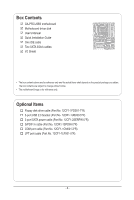
Box Contents GA-P55-USB3 motherboard Motherboard driver disk User's Manual Quick Installation Guide One IDE cable Two SATA change without notice. • The motherboard image is for reference only. Optional Items Floppy disk drive cable (Part No. 12CF1-1FD001-7*R) 2-port USB 2.0 bracket (Part No. 12CR1 - Gigabyte GA-P55-USB3 | Manual - Page 7
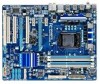
-USB3 Motherboard Layout KB_USBj R_SPDIF CPU_FAN ATX_12V_2X4 R_USB_2 R_USB_1 R_USB30 LGA1156 PWR_FAN PHASE LED ATX USB_LAN NEC AUDIO F_AUDIO RTL8111D PCIEX16 GA-P55-USB3 PCIEX1_1 (Note) SYS_FAN1 IDE SYS_FAN2 DDR3_2 DDR3_1 DDR3_4 DDR3_3 PCIEX1_2 BAT CODEC PCI1 PCIEX4_X1 GIGABYTE - Gigabyte GA-P55-USB3 | Manual - Page 8
GA-P55-USB3 Motherboard Block Diagram PCIe CLK (100 MHz) 1 PCI Express x16 LGA1156 CPU CPU CLK+/- (133 MHz) DDR3 2200/1333/1066/800 MHz Dual Channel Memory PCI Express Bus x16 LAN Gen 2 RJ45 RTL8111D Switch x1 x1 Gen 1 PCI Express Bus x1 PCIe CLK (100 MHz) PCI Express x1 (PCIEX1_1) - Gigabyte GA-P55-USB3 | Manual - Page 9
manual and follow these procedures: • Prior to installation, do not remove or break motherboard S/N wrist strap when handling electronic com- ponents such as a motherboard, CPU or memory. If you do not have an ESD wrist strap, steps or have a problem related to the use of the product, please consult - Gigabyte GA-P55-USB3 | Manual - Page 10
Specifications CPU Support for an Intel® Core™ i7 series processor/Intel® Core™ i5 series processor in the LGA1156 package (Go to GIGABYTE's website for the latest CPU support list.) L3 cache varies with CPU Chipset Intel® P55/H55 Express Chipset Memory Audio 4 x 1.5V - Gigabyte GA-P55-USB3 | Manual - Page 11
panel header w 1 x front panel audio header w 1 x CD In connector w 1 x S/PDIF In header w 1 x S/PDIF Out header w 2 x USB 2.0/1.1 headers w 1 x serial port header w 1 x parallel port header w 1 x clearing CMOS jumper Back Panel w 1 x PS/2 keyboard - Gigabyte GA-P55-USB3 | Manual - Page 12
) Operating System w Support for Microsoft® Windows® 7/Vista/XP Form Factor w ATX Form Factor; 30.5cm x 24.4cm j Only for P55 Chipset. (Note 1) Due to Windows 32-bit operating system limitation, when more than 4 GB of physical memory is installed, the actual memory size displayed will be - Gigabyte GA-P55-USB3 | Manual - Page 13
before you begin to install the CPU: • Make sure that the motherboard supports the CPU. (Go to GIGABYTE's website for the latest CPU support list.) • Always turn off the computer and unplug the power cord from the power outlet before installing the CPU to prevent hardware damage. • Locate the - Gigabyte GA-P55-USB3 | Manual - Page 14
B. Follow the steps below to correctly install the CPU into the motherboard CPU socket. Before installing the CPU, make sure to turn off the computer and unplug the power cord from the power outlet to prevent damage to the CPU. Step 1: Gently press the CPU socket lever handle down and away from the - Gigabyte GA-P55-USB3 | Manual - Page 15
pin. Check that the Male and Female push pins are joined closely. (Refer to your CPU cooler installation manual for instructions on installing the cooler.) Step 5: After the installation, check the back of the motherboard. If the push pin is inserted as the picture above shows, the installation is - Gigabyte GA-P55-USB3 | Manual - Page 16
guidelines before you begin to install the memory: • Make sure that the motherboard supports the memory. It is recommended that memory of the same capacity, brand, speed, and chips be used. (Go to GIGABYTE's website for the latest memory support list.) • Always turn off the computer and unplug - Gigabyte GA-P55-USB3 | Manual - Page 17
unplug the power cord from the power outlet to prevent damage to the memory module. DDR3 and DDR2 DIMMs are not compatible to each other or DDR DIMMs. Be sure to install DDR3 DIMMs on this motherboard. Notch DDR3 DIMM A DDR3 memory module has a notch, so it can only fit in one direction. Follow - Gigabyte GA-P55-USB3 | Manual - Page 18
an expansion card: • Make sure the motherboard supports the expansion card. Carefully read the manual that came with your expansion card. • Always If necessary, go to BIOS Setup to make any required BIOS changes for your expansion card(s). 7. Install the driver provided with the expansion card - Gigabyte GA-P55-USB3 | Manual - Page 19
to an external audio system that supports digital coaxial audio. Before using this feature, ensure that your audio system provides a coaxial digital audio in connector. USB 3.0/2.0 Port The USB 3.0 port supports the USB 3.0 specification and is compatible to the USB 2.0/1.1 specification. Use this - Gigabyte GA-P55-USB3 | Manual - Page 20
to perform different functions via the audio software. Only microphones still MUST be connected to the default Mic in jack ( ). Refer to the instructions on setting up a 2/4/5.1/7.1-channel audio configuration in Chapter 5, "Configuring 2/4/5.1/7.1-Channel Audio." Hardware Installation - 20 - - Gigabyte GA-P55-USB3 | Manual - Page 21
ATX 3) CPU_FAN 4) SYS_FAN1/2 5) PWR_FAN 6) FDD 7) IDE 8) SATA2_0/1/2/3/4/5 9) GSATA2_6/7 10) BAT 11) F_PANEL 12) F_AUDIO 13) CD_IN 14) SPDIF_I 15) SPDIF_O 16) F_USB1/F_USB2 17) LPT 18) COMA 19) CLR_CMOS 20) PHASE LED attached to the connector on the motherboard. - 21 - Hardware Installation - Gigabyte GA-P55-USB3 | Manual - Page 22
ATX (2x4 12V Power Connector and 2x12 Main Power Connector) With the use of the power connector, the power supply can supply enough stable power to all the components on the motherboard CPU manufacturer when using an Intel Extreme Edition CPU The power connectors are compatible with power supplies - Gigabyte GA-P55-USB3 | Manual - Page 23
a fan cable, be sure to connect it in the correct orientation (the black connector wire is the ground wire). The motherboard supports CPU fan speed control, which requires the use of a CPU fan with fan speed control design. For optimum heat dissipation, it is recom- mended that a system fan be - Gigabyte GA-P55-USB3 | Manual - Page 24
SATA 3Gb/s standard and are compatible with SATA 1.5Gb/s standard. Each SATA connector supports a single SATA device. The P55 Chipset supports RAID 0, RAID 1, RAID 5, and RAID 10. Refer to Chapter 5, "Configuring SATA Hard Drive(s)," for instructions on configuring a RAID array. 7 SATA2_3 SATA2_4 - Gigabyte GA-P55-USB3 | Manual - Page 25
/s standard and are compatible with SATA 1.5Gb/s standard. Each SATA connector supports a single SATA device. The GIGABYTE SATA2 controller supports RAID 0, RAID 1, and JBOD. Refer to Chapter 5, "Configuring SATA Hard Drive(s)," for instructions on configuring a RAID array. 7 GSATA2_6 1 GSATA2_7 - Gigabyte GA-P55-USB3 | Manual - Page 26
a beep code. One single short beep will be heard if no problem is detected at system startup. If a problem is detected, the BIOS may issue beeps in different patterns to indicate the problem. Refer to Chapter 5, "Troubleshooting," for information about beep codes. • HD (Hard Drive Activity LED, Blue - Gigabyte GA-P55-USB3 | Manual - Page 27
Header) The front panel audio header supports Intel High Definition audio (HD) and AC'97 audio. You may connect your chassis front panel audio module to this header. Make sure the wire assignments of the module connector match the pin assignments of the motherboard header. Incorrect connection - Gigabyte GA-P55-USB3 | Manual - Page 28
No. Definition 1 Power 2 SPDIFI 3 GND 1 15) SPDIF_O (S/PDIF Out Header) This header supports digital S/PDIF Out and connects a S/PDIF digital audio cable (provided by expansion cards) for digital audio output from your motherboard to certain expansion cards like graphics cards and sound cards. For - Gigabyte GA-P55-USB3 | Manual - Page 29
, be sure to turn off your computer and unplug the power cord from the power outlet to prevent damage to the USB bracket. 17) LPT (Parallel Port Header) The LPT header can provide one parallel port via an optional LPT port cable. For purchasing the optional LPT - Gigabyte GA-P55-USB3 | Manual - Page 30
9 NRI- 10 No Pin 19) CLR_CMOS (Clearing CMOS Jumper) Use this jumper to clear the CMOS values (e.g. date information and BIOS configurations) and reset the CMOS values to factory defaults. To clear the CMOS values, place a jumper cap on the two pins to temporarily short the two pins or use a metal - Gigabyte GA-P55-USB3 | Manual - Page 31
20) PHASE LED The number of lighted LEDs indicates the CPU loading. The higher the CPU loading, the more the number of lighted LEDs. To enable the Phase LED display function, please first enable Dynamic Energy Saver™ 2. Refer to Chapter 4, "Dynamic Energy Saver™ 2," for more details. - 31 - - Gigabyte GA-P55-USB3 | Manual - Page 32
Hardware Installation - 32 - - Gigabyte GA-P55-USB3 | Manual - Page 33
problems using the current version of BIOS, it is recommended that you not flash the BIOS. To flash the BIOS, do it with caution. Inadequate BIOS flashing may result in system malfunction. • BIOS will emit a beep code during the POST. Refer to Chapter 5, "Troubleshooting," for the beep codes - Gigabyte GA-P55-USB3 | Manual - Page 34
v6.00PG, An Energy Star Ally Copyright (C) 1984-2009, Award Software, Inc. Motherboard Model BIOS Version P55-USB3 D4 . . . . : BIOS Setup : XpressRecovery2 : Boot Menu : Qflash 12/04/2009-P55-7A89TG0DC-00 Function Keys Function Keys Function Keys: : POST SCREEN Press - Gigabyte GA-P55-USB3 | Manual - Page 35
BIOS Version: D4) CMOS Setup Utility-Copyright (C) 1984-2009 Award Software MB Intelligent Tweaker(M.I.T.) Standard CMOS Features Advanced BIOS Features Save & Exit Setup Change CPU's Clock & Voltage F11: Save CMOS to BIOS F12: Load CMOS from BIOS BIOS Setup Program Function Keys - Gigabyte GA-P55-USB3 | Manual - Page 36
the clock, frequency and voltages of your CPU, memory, etc. Standard CMOS Features Use this menu to configure the system time and date, hard drive types, floppy disk drive types, and the type of errors that stop the system boot, etc. Advanced BIOS Features Use this menu to configure the device - Gigabyte GA-P55-USB3 | Manual - Page 37
clear the CMOS values and reset the board to default values.) M.I.T. Current Status This screen provides information on CPU/memory frequencies/parameters. Advanced Frequency Settings CMOS (Note) This item appears only if you install a memory module that supports this feature. - 37 - BIOS Setup - Gigabyte GA-P55-USB3 | Manual - Page 38
Advanced CPU Core Features CMOS Setup Utility-Copyright (C) 1984-2009 Award Software Advanced CPU Core Features Intel(R) Turbo Boost Tech. CPU Cores Enabled (Note) CPU Multi-Threading (Note) CPU Enhanced Halt (C1E) (Note) C3/C6/C7 State Support (Note) CPU Thermal Monitor (Note) CPU EIST - Gigabyte GA-P55-USB3 | Manual - Page 39
after overclocking, please wait for 20 seconds to allow for automated system reboot, or clear the CMOS values to reset the board to default values. (Default: Disabled) (Note) This item is present only if you install a CPU that supports this feature. For more information about Intel CPUs' unique - Gigabyte GA-P55-USB3 | Manual - Page 40
System Memory Multiplier settings. PCI Express Frequency(Mhz) Allows you to manually set CPU Clock Skew Allows you to set the CPU clock prior to the Chipset clock. Options are: 0ps~750ps. (Default: 0ps) (Note) This item appears only if you install a memory module that supports this feature. BIOS - Gigabyte GA-P55-USB3 | Manual - Page 41
set to Disabled, this item will display as 1.5V. When Extreme Memory Profile (X.M.P.) is set to Profile1 or Profile2, this item will display the value based on the SPD data on the XMP memory. (Note) This item appears only if you install a memory module that supports this feature. - 41 - BIOS Setup - Gigabyte GA-P55-USB3 | Manual - Page 42
CPU being used. Channel Interleaving Options are: Auto (default), 1~6. Rank Interleaving Options are: Auto (default), 1~4. >>>>> Channel A/B Timing Settings CMOS tRFC 60 x tRTP 5 x tFAW 16 x Command Rate (CMD) 1 >>>>> Channel A Misc Timing Control x B2B . BIOS Setup - 42 - - Gigabyte GA-P55-USB3 | Manual - Page 43
Auto (default), 1~63. Command Rate(CMD) Options are: Auto ( CMOS CPU Load-Line Calibration [Auto] CPU Core 1.050V [Auto] CPU PLL 1.800V [Auto] feature adjusts Vdroop, keeping the CPU voltage more constant under light and heavy CPU load. Disabled sets the CPU voltage following Intel - Gigabyte GA-P55-USB3 | Manual - Page 44
default is Auto. Dynamic Vcore(DVID) The default is Auto. QPI/Vtt Voltage The default is Auto. >>> MCH/ICH PCH Core The default is Auto. CPU PLL The default is Auto. >>> DRAM DRAM Voltage The default is Auto. DRAM Termination The default is Auto. Ch-A Data VRef. The default is Auto - Gigabyte GA-P55-USB3 | Manual - Page 45
the BIOS version, CPU base clock, CPU frequency, memory frequency, total memory size , CPU temperature, Chipset temperature, Vcore, and memory voltage. (Note) This item is present only if you install a CPU that supports this feature. For more information about Intel CPUs' unique features, please - Gigabyte GA-P55-USB3 | Manual - Page 46
ESC: Exit F1: General Help F7: Optimized Defaults CMOS Setup Utility-Copyright (C) 1984-2009 Award Software Standard CMOS Features Extended Memory Total Memory 1022M 1024M Item Help Menu Level Move Enter of the device during the POST for faster system startup. BIOS Setup - 46 - - Gigabyte GA-P55-USB3 | Manual - Page 47
hard drive specifications. If you wish to enter the parameters manually, refer to the information on the hard drive. Capacity Approximate for all other errors. Memory These fields are read-only and are determined by the BIOS POST. Base Memory Also called conventional memory. Typically, 640 KB - Gigabyte GA-P55-USB3 | Manual - Page 48
hard drive and to issue warnings when a third party hardware monitor utility is installed. (Default: Disabled) (Note) This item is present only if you install a CPU that supports this feature. For more information about Intel CPUs' unique features, please visit Intel's website. BIOS Setup - 48 - - Gigabyte GA-P55-USB3 | Manual - Page 49
operating system such as Windows NT4.0. (Default: Disabled) No-Execute Memory Protect (Note) Enables or disables Intel Execute Disable Bit function you install a CPU that supports this feature. For more information about Intel CPUs' unique features, please visit Intel's website. - 49 - BIOS Setup - Gigabyte GA-P55-USB3 | Manual - Page 50
) Disabled will turn off all of the USB functionalities below. USB Legacy Function Allows USB keyboard to be used in MS-DOS. (Default: Enabled) j Only for P55 Chipset. (Note) On H55 Chipset motherboards, this item is present only when an Intel Lynnfield CPU is installed. BIOS Setup - 50 - - Gigabyte GA-P55-USB3 | Manual - Page 51
If no cable problem is detected on the LAN cable connected to a Gigabit hub or a 10/100 Mbps hub, the following message will appear: Start detecting at Port..... Link Detected --> 100Mbps Cable Length= 30m (Note) On H55 Chipset motherboards, this item is present only when an Intel Lynnfield CPU is - Gigabyte GA-P55-USB3 | Manual - Page 52
interface specification that allows the storage driver to enable advanced Serial ATA features such as Native Command Queuing and hot plug. RAID/IDE Enables RAID for the SATA controller; the IDE controller still operates in IDE mode. Onboard SATA/IDE Device (GIGABYTE SATA2, IDE and GSATA2_6 - Gigabyte GA-P55-USB3 | Manual - Page 53
system to enter the ACPI S3 (Suspend to RAM) sleep state (default). In S3 sleep state Note: To use this function, you need an ATX power supply providing at least 1A on the supports wake-up function. (Default: Enabled) (Note) Supported on Windows 7/Vista operating system only. - 53 - BIOS Setup - Gigabyte GA-P55-USB3 | Manual - Page 54
Windows 7/Vista. This item is configurable only if the HPET Support is set to Enabled. (Default: 32-bit mode) Power On By Mouse Allows the system to be turned on by a PS/2 mouse wake-up event. Note: To use this function, you need an ATX without entering the password to clear the password settings. AC - Gigabyte GA-P55-USB3 | Manual - Page 55
detection device attached to the motherboard CI header. If the system chassis cover is removed, this field will show "Yes", otherwise it will show "No". To clear the chassis intrusion status record, set Reset Case Open Status to Enabled, save the settings to the CMOS, and then restart your system - Gigabyte GA-P55-USB3 | Manual - Page 56
mode. (Default) Voltage Sets Voltage mode for a 3-pin CPU fan. PWM Sets PWM mode for a 4-pin CPU fan. Note: The Voltage mode can be set for a 3-pin CPU fan or a 4-pin CPU fan. However, for a 4-pin CPU fan that is not designed following Intel PWM fan specifications, selecting PWM mode may not - Gigabyte GA-P55-USB3 | Manual - Page 57
and most stable BIOS settings for the motherboard. 2-10 Load Optimized Defaults CMOS Setup Utility-Copyright (C) 1984-2009 Award Software MB Intelligent Tweaker(M.I.T.) Load Fail-Safe Defaults Standard CMOS Features Load Optimized Defaults Advanced BIOS Features Set Supervisor Password - Gigabyte GA-P55-USB3 | Manual - Page 58
MB Intelligent Tweaker(M.I.T.) Standard CMOS Features Advanced BIOS Features Integrated Peripherals Power Management SetupEnter wish to make changes to BIOS settings. The user password only allows you to view the BIOS settings but not to make changes. To clear the password, press - Gigabyte GA-P55-USB3 | Manual - Page 59
-Copyright (C) 1984-2009 Award Software MB Intelligent Tweaker(M.I.T.) Load Fail-Safe Defaults Standard CMOS Features Advanced BIOS Features Load Optimized Defaults Save to CMOS and EXITSe(Yt S/Nup)?erYvisor Password Integrated Peripherals Set User Password Power Management Setup - Gigabyte GA-P55-USB3 | Manual - Page 60
BIOS Setup - 60 - - Gigabyte GA-P55-USB3 | Manual - Page 61
are installed, follow the on-screen instructions to restart your system. You can install other applications included in the motherboard driver disk. • For USB 2.0 driver support under the Windows XP operating system, please install the Windows XP Service Pack 1 or later. After installing the SP1 - Gigabyte GA-P55-USB3 | Manual - Page 62
applications that GIGABYTE develops and some free software. You can click the Install button on the right of an item to install it. 3-3 Technical Manuals This page provides GIGABYTE's application guides, content descriptions for this driver disk, and the motherboard manuals. Drivers Installation - Gigabyte GA-P55-USB3 | Manual - Page 63
3-4 Contact For the detailed contact information of the GIGABYTE Taiwan headquarter or worldwide branch offices, click the URL on this page to link to the GIGABYTE website. 3-5 System This page provides the basic system information. - 63 - Drivers Installation - Gigabyte GA-P55-USB3 | Manual - Page 64
Center To update the BIOS, drivers, or applications, click the Download Center button to link to the GIGABYTE website. The latest version of the BIOS, drivers, or applications will be displayed. 3-7 New Utilities This page provides a quick link to GIGABYTE's lately developed utilities for users - Gigabyte GA-P55-USB3 | Manual - Page 65
compatible graphics card • Windows XP with SP1 or later, Windows Vista • Xpress Recovery and Xpress Recovery2 are different utilities. For example, a backup file created with Xpress Recovery cannot be restored using Xpress Recovery2. • USB hard drives are not supported. • Hard drives in RAID/AHCI - Gigabyte GA-P55-USB3 | Manual - Page 66
space, Xpress Recovery2 cannot save the backup file. B. Accessing Xpress Recovery2 1. Boot from the motherboard driver disk to access Xpress Recovery2 for the first time. When you see the following message: 2: When finished, go to Disk Management to check disk allocation. Unique Features - 66 - - Gigabyte GA-P55-USB3 | Manual - Page 67
will be present in Disk Management and hard drive space will be freed up. F. Exiting Xpress Recovery2 Select REBOOT to exit Xpress Recovery2. - 67 - Unique Features - Gigabyte GA-P55-USB3 | Manual - Page 68
4-2 BIOS Update Utilities GIGABYTE motherboards provide two unique BIOS update tools, Q-Flash™ and @BIOS™. GIGABYTE Q-Flash and @BIOS are easy-to-use and allow you to update the BIOS without the need to enter MS-DOS mode. Additionally, this motherboard features the DualBIOS™ design, which enhances - Gigabyte GA-P55-USB3 | Manual - Page 69
Loa d CMO S Default Enable HDD 1-0 Upda te BIOS from Drive Save BIOS to Drive Enter : Run hi:Move ESC:Reset F10:Power Off Total size : 0 Free size : 0 3. Select the BIOS update file and press . Make sure the BIOS update file matches your motherboard model - Gigabyte GA-P55-USB3 | Manual - Page 70
devices after a BIOS update, so we recommend that you reload BIOS defaults. CMOS Setup Utility-Copyright (C) 1984-2009 Award Software MB Intelligent Tweaker(M.I.T.) Load Fail-Safe Defaults Standard CMOS Features Load Optimized Defaults Advanced BIOS Features Set Supervisor Password - Gigabyte GA-P55-USB3 | Manual - Page 71
. If the BIOS update file for your motherboard is not present on the @BIOS server site, please manually download the BIOS update file from GIGABYTE's website and follow the instructions in "Update the BIOS without Using the Internet Update Function" below. 2. Update the BIOS without Using the - Gigabyte GA-P55-USB3 | Manual - Page 72
in EasyTune 6 may differ by motherboard model. Grayed-out area(s) indicates that the item is not configurable or the function is not supported. Incorrectly doing overclock/overvoltage may result in damage to the hardware components such as CPU, chipset, and memory and reduce the useful life of - Gigabyte GA-P55-USB3 | Manual - Page 73
button. Featuring an advanced proprietary hardware and software design, GIGABYTE Dynamic Phase LED On/Off Switch (Default: On) 16 Live Utility Update (Check for the latest utility version) • The above data is for reference only. Actual performance may vary depending on motherboard model. • CPU - Gigabyte GA-P55-USB3 | Manual - Page 74
/Help 14 Motherboard Phase LED On/Off Switch (Default: On) 15 Live Utility Update (Check for CPU Enhanced Halt (C1E) and CPU EIST Function items in the BIOS Setup program are set to Enabled. (Note 2) 1: Smart FAN/CPU (default); 2: Smart FAN/CPU/VGA/HDD; 3: Smart FAN/CPU/VGA/HDD/Chipset/ Memory - Gigabyte GA-P55-USB3 | Manual - Page 75
Share After installing Q-Share from the motherboard driver disk, go to Start>All Programs>GIGABYTE>Q-Share. exe to launch the Folder : C:\Q-ShareFolder Update Q-Share ... Changes the data folder to be shared (Note) Updates Q-Share online Displays the current Q-Share version Exits - Gigabyte GA-P55-USB3 | Manual - Page 76
4-6 Smart 6™ GIGABYTE Smart 6™ (Note 1) is designed with user-friendliness in mind, and Instructions: Select the Enable check box below the BIOS QuickBoot or OS QuickBoot item and then click Save to save the settings. SMART QuickBoost SMART QuickBoost features quick and effortless CPU overclocking - Gigabyte GA-P55-USB3 | Manual - Page 77
) in Windows Vista. Instructions: In feature that can record personal passwords and important dates, and remind users of the dates. It also stores the recorded data in the main and backup BIOS simultaneously, which can prevent loss of the data in case the system/hard drive fails. Instructions - Gigabyte GA-P55-USB3 | Manual - Page 78
or copied to an external storage device (Note 5). Instructions: Select the Enable check box at the bottom not be able to use the "Safely Remove Hardware" feature in the operating system with SMART Recorder enabled. To BIOS Setup program to prevent the system time being changed by other users. - Gigabyte GA-P55-USB3 | Manual - Page 79
cell phone key, make sure your motherboard has a Bluetooth receiver and you have RAM mode Disables this function The Bluetooth dongle included in the motherboard package(Note 2) allows you to wake up the system from Suspend to RAM depends on the motherboard models. Before installing the Bluetooth dongle, be - Gigabyte GA-P55-USB3 | Manual - Page 80
the Intel SATA controllers. Step 2: Install the RAID driver and operating system The X.H.D utility supports Windows 7/Vista/XP. Before installing the operating system, you have to load the SATA controller driver first. Without the driver, the hard drive may not be recognized during the Windows setup - Gigabyte GA-P55-USB3 | Manual - Page 81
identical model and capacity). If you do not want to create RAID, you may prepare only one hard drive. • An empty formatted floppy disk. • Windows Vista/XP setup disk. • Motherboard driver disk. 5-1-1 Configuring Intel P55 SATA Controllers A. Installing SATA hard drive(s) in your computer Attach one - Gigabyte GA-P55-USB3 | Manual - Page 82
press to enter BIOS Setup during the POST (Power-On Self-Test). To create RAID, set PCH SATA Control Mode under the Integrated Peripherals menu to RAID(XHD) (Figure 1) (IDE by default). If you do not want to create RAID, set this item to IDE or AHCI. CMOS Setup Utility-Copyright (C) 1984 - Gigabyte GA-P55-USB3 | Manual - Page 83
C. Configuring a RAID array in RAID BIOS Enter the RAID BIOS setup utility to configure a RAID array. Skip this step and proceed with the installation of Windows operating system for a non-RAID configuration. Step 1: After the POST memory test begins and before the operating system boot begins, - Gigabyte GA-P55-USB3 | Manual - Page 84
Figure 4). RAID levels supported include RAID 0, RAID 1, Recovery, RAID 10, and RAID 5 (the selections available depend on the number of the hard drives being installed). Press to proceed. Intel(R) Rapid Storage Technology - option ROM - 9.5.0.1037 Copyright(C) 2003-09 Intel Corporation. All - Gigabyte GA-P55-USB3 | Manual - Page 85
(0) Member Disk(0) [hi]-Select [ESC]-Exit Figure 7 [ENTER]-Select Menu To exit the RAID BIOS utility, press or select 5. Exit in MAIN MENU. Now, you can proceed to create the SATA RAID/AHCI driver diskette and install the SATA RAID/AHCI driver and operating system. - 85 - Appendix - Gigabyte GA-P55-USB3 | Manual - Page 86
Storage Technology - option ROM - 9.5.0.1037 Copyright(C) 2003-09 Intel Corporation. All Rights Reserved. [ MAIN MENU ] 1. Create RAID Volume 2. Delete RAID Volume 5. Exit 3. Reset Disks to Non-RAID 4. Recovery Volume Options RAID Volumes : None defined. [ DISK/VOLUME INFORMATION ] Physical - Gigabyte GA-P55-USB3 | Manual - Page 87
Status Non-RAID Disk Non-RAID Disk Choose the RAID level: update data from the master drive to the recovery drive manually using the Update Volume function of the Intel sync option: On Request: volume is updated manually Continuous: volume is updated automatically [hi]-Change [TAB]-Next [ESC - Gigabyte GA-P55-USB3 | Manual - Page 88
or to abort. Intel(R) Rapid Storage Technology - option ROM - 9.5.0.1037 Copyright(C) 2003-09 Intel Corporation. All Rights Reserved. you wa[nHt tEoLdPel]ete "Volume0"? (Y/N) : Deleting a volume will reset the disks to non-RAID. WARNING: ALL DISK DATA WILL BE DELETED. (This does not apply - Gigabyte GA-P55-USB3 | Manual - Page 89
motherboard, the GSATA2_6 and GSATA2_7 ports are supported by the GIGABYTE SATA2 SATA controller. Then connect the power connector from your power supply to the hard drive. B. Configuring SATA controller mode in BIOS Setup Make sure to configure the SATA controller mode correctly in system BIOS - Gigabyte GA-P55-USB3 | Manual - Page 90
C. Configuring a RAID array in RAID BIOS Enter the RAID BIOS setup utility to configure a RAID array. Skip this step and proceed to the installation of Windows operating system for a non-RAID configuration. After the POST memory test begins and before the operating system boot begins, look for a - Gigabyte GA-P55-USB3 | Manual - Page 91
GB Gigabyte Technology Corp. RAID Setup Utility v1.07.06 [ Hard Disk Drive List ] Model Name HDD0: ST3120026AS HDD1: ST3120026AS Available 120 GB 120 GB Type/Status Non-RAID Non-RAID Confirm Creation [ RAID Disk Drive List ] [ Help ] Select RAID Level RAID 0 RAID 1 JBOD - Gigabyte GA-P55-USB3 | Manual - Page 92
a RAID mode is selected, RAID BIOS automatically assigns the two hard drives installed as the RAID drives. 4. Set Block Size (RAID 0 only RAID ] Name: Level: Disks: Block: Size: GRAID 0-Stripe Select Disk 128 KB 240 GB Gigabyte Technology Corp. RAID Setup Utility v1.07.06 [ Hard Disk Drive List - Gigabyte GA-P55-USB3 | Manual - Page 93
in the Main Menu block to move the selection bar to the RAID Disk Drive List block. Select the array and press . A small window displaying the array information will appear in the center of the screen (Figure 9). Gigabyte Technology Corp. RAID Setup Utility v1.07.06 [ Main Menu ] Create - Gigabyte GA-P55-USB3 | Manual - Page 94
the RAID BIOS utility, then press (Figure 10). [ Main Menu ] Create RAID Disk Drive Delete RAID Disk Drive Revert HDD to Non-RAID Solve Mirror Conflict Rebuild Mirror Drive Save And Exit Setup Exit Without Saving Gigabyte Technology Corp. RAID Setup Utility v1.07.06 [ Hard Disk Drive List - Gigabyte GA-P55-USB3 | Manual - Page 95
recognized during the Windows setup process. First of all, copy the driver for the SATA controller from the motherboard driver disk to a floppy disk. For installing Windows Vista, you also can copy the SATA controller driver from the motherboard driver disk to a USB flash drive. See the instructions - Gigabyte GA-P55-USB3 | Manual - Page 96
will then appear asking you to specify additional device. Windows Setup Press F6 if you need to install a third party SCSI or RAID driver. Figure 1 Step 2: For the Intel P55: Insert the floppy disk containing the SATA RAID/AHCI driver and press . Then a controller menu similar to Figure 2 below - Gigabyte GA-P55-USB3 | Manual - Page 97
to configure a SCSI Adapter for use with Windows, using a device support disk provided by an adapter manufacturer. Select the SCSI Adapter you want from the following list, or press ESC to return to the previous screen. RAID/AHCI Driver for GIGABYTE GBB36X Controller (x32) ENTER=Select F3 - Gigabyte GA-P55-USB3 | Manual - Page 98
the Intel P55: Step 1: Restart your system to boot from the Windows Vista setup disk and perform standard OS installation steps. When a screen similar to that below appears (RAID hard drive will not be detected at this stage), select Load Driver (Figure 4). Figure 4 Step 2: Insert the motherboard - Gigabyte GA-P55-USB3 | Manual - Page 99
Step 3: When a screen as shown in Figure 6 appears, select Intel(R) ICH8R/ICH9R/ICH10R/DO/5 Series/3400 Series SATA RAID Controller and click Next. Figure 6 Step 4: After the driver is loaded, select the RAID/AHCI drive(s) where you want to install the operating system and then click Next to - Gigabyte GA-P55-USB3 | Manual - Page 100
flash drive that contains the SATA RAID/ AHCI driver (Method B), then specify the location of the driver (Figure 9). Note: For users using a SATA optical drive, be sure to copy the driver files from the motherboard driver disk to a USB flash drive before installing Windows Vista (go to the BootDrv - Gigabyte GA-P55-USB3 | Manual - Page 101
Step 3: When a screen as shown in Figure 10 appears, select GIGABYTE GBB36X Controller and click Next. Figure 10 Step 4: After the driver is loaded, select the RAID/AHCI drive(s) where you want to install the operating system and then click Next to continue the OS installation (Figure 11). Figure - Gigabyte GA-P55-USB3 | Manual - Page 102
to rebuild a RAID 1 array. (Note: The new drive must have equal or greater capacity than the old one.) For the Intel P55: Turn off Intel Corporation. All Rights Reserved. [ MAIN MENU ] 1. Create RAID Volume 2. Delete RAID Volume 5. Exit 3. Reset Disks to Non-RAID 4. Recovery Volume Options RAID - Gigabyte GA-P55-USB3 | Manual - Page 103
has been installed from the motherboard driver disk. Then launch the Intel Rapid Stroage Technology utility from All Programs in the Start menu. Step 1: Go to the Manage menu and click Rebuild to another disk in Manage Volume. Step 2: Select a new drive to rebuild the RAID and click Rebuild. The - Gigabyte GA-P55-USB3 | Manual - Page 104
Recovery Volume only) When two hard drives are set to Recovery Volume in Update on Request mode, you can restore the master drive data to the last instructions to complete and exit the RAID Configuration Utility. Intel(R) Rapid Storage Technology - option ROM - 9.5.0.1037 Copyright(C) 2003-09 Intel - Gigabyte GA-P55-USB3 | Manual - Page 105
Setup Exit Without Saving Gigabyte Technology Corp. RAID Setup Utility v1.07.06 [ Hard Disk Drive List ] Model Name HDD0: ST3120026AS HDD1: ST3120026AS Capacity 120 GB 120 GB Type/Status RAID Inside Non-RAID [ RAID Disk Drive List ] Model Name RDD0: GRAID RAID Level 1-Mirror Capacity - Gigabyte GA-P55-USB3 | Manual - Page 106
has been installed from the motherboard driver disk. Launch the GIGABYTE RAID CONFIGURER from All Programs in the Start menu. Step 1: In the GIGABYTE RAID CONFIGURER screen, right-click on the array to be rebuilt in the RAID LIST block. Select Rebuild Raid. (Or click the Rebuild icon in the tool - Gigabyte GA-P55-USB3 | Manual - Page 107
using an HD front panel audio module), refer to instructions on the next page. High Definition Audio (HD Audio) HD Audio includes multiple high quality digital-to-analog converters (DACs) that support 44.1KHz/48KHz/ 96KHz/192KHz sampling rate. HD Audio features multistreaming capabilities that allow - Gigabyte GA-P55-USB3 | Manual - Page 108
tab. In the Speaker Configuration list, select Stereo, Quadraphonic, 5.1 Speaker, or 7.1 Speaker according to the type of speaker configuration you wish to set up. Then the speaker setup is completed. B. Configuring Sound Effect You may configure an audio environment on the Sound Effects tab - Gigabyte GA-P55-USB3 | Manual - Page 109
allows you to input digital audio signals to the computer for audio processing. S/PDIF In Cable Optical S/PDIF In Coaxial S/PDIF In 1. Installing the S/PDIF In Cable: Step 1: First, attach the connector at the end of the cable to the SPDIF_I header on your motherboard. Step 2: Secure the metal - Gigabyte GA-P55-USB3 | Manual - Page 110
Out The S/PDIF Out jacks can transmit audio signals to an external decoder for decoding to get the best audio quality. 1. Connecting a S/PDIF Out Cable (either one) to an external decoder for transmitting the S/PDIF digital audio signals. 2. Configuring S/PDIF Out: On the Digital Output screen, - Gigabyte GA-P55-USB3 | Manual - Page 111
5-2-3 Configuring Microphone Recording Step 1: After installing the audio driver, the HD Audio Manager icon will appear in the notification area. Double-click the icon to access the HD Audio Manager. Step 2: Connect your microphone to the Mic in jack (pink) on the back panel or the Mic in jack (pink - Gigabyte GA-P55-USB3 | Manual - Page 112
, click Start, point to All Programs, point to Accessories, and then click Sound Recorder to begin the sound recording. * Enabling Stereo Mix If the HD Audio Manager does not display the recording device you wish to use, refer to the steps below. The following steps explain how to enable Stereo Mix - Gigabyte GA-P55-USB3 | Manual - Page 113
Start Recording button . 3. To stop recording audio, click the Stop Recording button . Be sure to save the recorded audio file upon completion. B. Playing the Recorded Sound You can play your recording in a digital media player program that supports your audio file format. - 113 - Appendix - Gigabyte GA-P55-USB3 | Manual - Page 114
go to the Support&Downloads\Motherboards\FAQ page on our website and search for "onboard HD audio driver." Q: What do the beeps emitted during the POST mean? A: The following Award BIOS beep code descriptions may help you identify possible computer problems. (For reference only.) 1 short: System - Gigabyte GA-P55-USB3 | Manual - Page 115
the CPU cooler power cable to the motherboard. Yes The problem is verified and solved. Check if the memory is installed properly on the memory slot. No Correctly insert the memory into the memory socket. Yes The problem is verified and solved. Insert the graphics card. Connect the ATX - Gigabyte GA-P55-USB3 | Manual - Page 116
"Save & Exit Setup" to save changes and exit BIOS Setup. The problem is verified and solved. Turn off the computer and connect problem, contact the place of purchase or local dealer for help. Or go to the Support&Downloads\Technical Service Zone page to submit your question. Our customer service - Gigabyte GA-P55-USB3 | Manual - Page 117
GIGABYTE. Our Commitment to Preserving the Environment In addition to high-efficiency performance, all GIGABYTE motherboards office, your household waste disposal service or where you purchased the Customer Care number listed in your product's user's manual and we will be glad to help you - Gigabyte GA-P55-USB3 | Manual - Page 118
Finally, we suggest that you practice other environmentally friendly actions by understanding and using the energy-saving features of this product (where applicable), recycling the inner and outer packaging (including shipping containers) this product was delivered in, and by disposing of or - Gigabyte GA-P55-USB3 | Manual - Page 119
- 119 - Appendix - Gigabyte GA-P55-USB3 | Manual - Page 120
Appendix - 120 - - Gigabyte GA-P55-USB3 | Manual - Page 121
- 121 - Appendix - Gigabyte GA-P55-USB3 | Manual - Page 122
Appendix - 122 - - Gigabyte GA-P55-USB3 | Manual - Page 123
- 123 - Appendix - Gigabyte GA-P55-USB3 | Manual - Page 124
Appendix - 124 - - Gigabyte GA-P55-USB3 | Manual - Page 125
- 125 - Appendix - Gigabyte GA-P55-USB3 | Manual - Page 126
Appendix - 126 - - Gigabyte GA-P55-USB3 | Manual - Page 127
Contact Us • GIGA-BYTE TECHNOLOGY CO., LTD. Address: No.6, Bau Chiang Road, Hsin-Tien, Taipei 231, Taiwan TEL: +886-2-8912-4000 FAX: +886-2-8912-4003 Tech. and Non-Tech. Support (Sales/Marketing) : http://ggts.gigabyte.com.tw WEB address (English): http://www.gigabyte.com.tw WEB address (Chinese): - Gigabyte GA-P55-USB3 | Manual - Page 128
.rs • Kazakhstan WEB address : http://www.gigabyte.kz You may go to the GIGABYTE website, select your language in the language list on the top right corner of the website. • GIGABYTE Global Service System To submit a technical or non-technical (Sales/Marketing) question, please link to: http://ggts
-
 1
1 -
 2
2 -
 3
3 -
 4
4 -
 5
5 -
 6
6 -
 7
7 -
8
-
9
-
10
-
11
-
12
-
13
-
14
-
15
-
16
-
17
-
18
-
19
-
20
-
21
-
22
-
23
-
24
-
25
-
26
-
27
-
28
-
29
-
30
-
31
-
32
-
33
-
34
-
35
-
36
-
37
-
38
-
39
-
40
-
41
-
42
-
43
-
44
-
45
-
46
-
47
-
48
-
49
-
50
-
51
-
52
-
53
-
54
-
55
-
56
-
57
-
58
-
59
-
60
-
61
-
62
-
63
-
64
-
65
-
66
-
67
-
68
-
69
-
70
-
71
-
72
-
73
-
74
-
75
-
76
-
77
-
78
-
79
-
80
-
81
-
82
-
83
-
84
-
85
-
86
-
87
-
88
-
89
-
90
-
91
-
92
-
93
-
94
-
95
-
96
-
97
-
98
-
99
-
100
-
101
-
102
-
103
-
104
-
105
-
106
-
107
-
108
-
109
-
110
-
111
-
112
-
113
-
114
-
115
-
116
-
117
-
118
-
119
-
120
-
121
-
122
-
123
-
124
-
125
-
126
-
127
-
128
 |
 |

GA-P55-USB3
LGA1156 socket motherboard for Intel
®
Core
™
i7 processor family/
Intel
®
Core
™
i5 processor family
User's Manual
Rev. 1001
12ME-P55USB3-1001R