Harbor Freight Tools 43389 User Manual
Harbor Freight Tools 43389 - 17 in. Floor Mount Drill Press Manual
 |
View all Harbor Freight Tools 43389 manuals
Add to My Manuals
Save this manual to your list of manuals |
Harbor Freight Tools 43389 manual content summary:
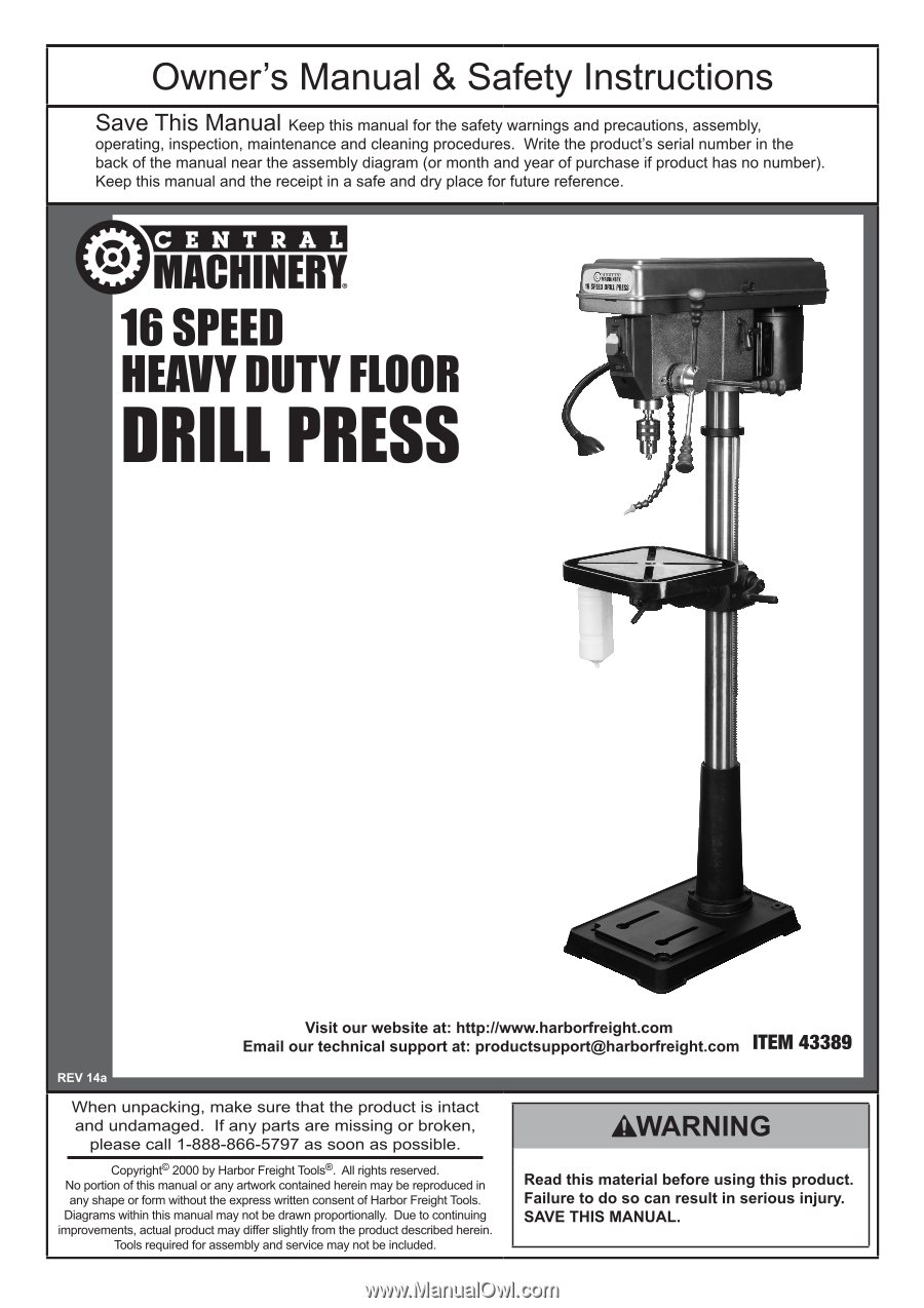
- Harbor Freight Tools 43389 | User Manual - Page 1
- Harbor Freight Tools 43389 | User Manual - Page 2
SAFETy Table of contents Safety 3 Specifications 6 Setup 6 Operation 9 Maintenance 11 Parts Lists and Diagrams 13 Warranty 16 WARNING SyMBOLS AND DEFINITIONS This is the safety injury. SETUp OpERATION MAINTENANcE Page 2 For technical questions, please call 1-888-866-5797. Item 43389 - Harbor Freight Tools 43389 | User Manual - Page 3
safest performance. Follow instructions for lubricating and changing accessories. 15. DISCONNECT TOOLS before servicing; when changing accessories, parts. Nonslip footwear is recommended. Wear protective hair covering to contain long hair. 17. USE RECOMMENDED ACCESSORIES. Consult the owner's manual - Harbor Freight Tools 43389 | User Manual - Page 4
tool to a different outlet. Drill press Safety Warnings For your Own Safety Read Instruction Manual Before Operating Drill press 1. Wear eye protection. a risk of injury to persons. 8. When servicing use only identical replacement parts. 9. Do not depress the spindle lock when 43389 MAINTENANcE - Harbor Freight Tools 43389 | User Manual - Page 5
SETUp Drill press Safety and then have regular medical check-ups to ensure medical problems are not being caused or worsened from use. Pregnant women in this manual. If any abnormal vibration occurs, stop use immediately. SAVE THESE INSTRUcTIONS. OpERATION MAINTENANcE Item 43389 For technical - Harbor Freight Tools 43389 | User Manual - Page 6
manual including parts listed in the following pages, refer to the Assembly Diagram near the end of this manual. Mounting Secure the tool to a supporting structure before use. Before assembly, bolt the Base to a flat, level, solid floor location capable of supporting the weight of the drill press - Harbor Freight Tools 43389 | User Manual - Page 7
. b. Push the Motor up until the top of the pulleys align. Hold Motor in place. c. Using a wrench, tighten four Hex Nuts (42) supporting the Motor. d. Turn the Motor Adjusting Knob (1) counterclockwise to release belt tension. Item 43389 For technical questions, please call 1-888-866-5797. Page 7 - Harbor Freight Tools 43389 | User Manual - Page 8
Pulley Guard center hole (See the Pulley Assembly Drawing at the end of this manual). c. Place the longer V-belt (A4) between Spindle Pulley (A6) and the Table is square (90º) to the Head Assembly and drill bit. a. Secure a three inches drill bit in the Chuck. b. Raise the Table to within four 43389 - Harbor Freight Tools 43389 | User Manual - Page 9
Instructions Read the ENTIRE IMpORTANT SAFETy INFORMATION section at the beginning of this manual close instantly. Setting the Depth Scale to Drill to a Specified Depth Locking Switch ( to bring the tip of the drill bit down, next to the hole touch the flutes of the drill. 2. Ensure that the bit - Harbor Freight Tools 43389 | User Manual - Page 10
to drill the hole. While drilling, watch the pointer and scale on the Depth Stop Ring. Stop turning the Feed Handle when the pointer and scale indicate the desired depth. 7. Turn the Drill Press OFF. OpERATION MAINTENANcE Page 10 For technical questions, please call 1-888-866-5797. Item 43389 - Harbor Freight Tools 43389 | User Manual - Page 11
problem parts, • cracked or broken parts service technician. Belt Inspection and Tensioning 1. Examine belt for cracks, tears in the backing, and other damage. 2. Replace belt if damaged, following the instructions 43389 For technical questions, please call 1-888-866-5797. Page 11 - Harbor Freight Tools 43389 | User Manual - Page 12
the (outer) Hex Nut. Troubleshooting problem possible causes Likely Solutions Tool will Press reset button on tool. 4. Internal damage or wear. (Carbon 4. Have technician service brushes. 1. Have technician service tool. 2. Belt (if servicing the tool. Disconnect power supply before service - Harbor Freight Tools 43389 | User Manual - Page 13
parts List and Diagram part 1 2 3 4 5 6 7 8 9 10 11 12 13 14 15 16 17 18 19 20 21 22 25 26 27 28 Description Motor Adjusting Knob Socket Set Screw Belt Tension Handle Stop Pin Ring Depth Stop w/ Scale Depth Screw Lock Hub Guide and Trim part 29a 30 Clamp Support Motor Bracket Bolt Support Screw - Harbor Freight Tools 43389 | User Manual - Page 14
M6x1.0-12 Set Screw, M10x1.5-12 part A11 A12 A13 A14 A15 A16 A17 PARTS LIST AND ASSEMBLY DIAGRAM IN THIS MANUAL PARTS OF THE PRODUCT. IN FACT, THE MANUFACTURER AND/OR DISTRIBUTOR EXPRESSLY STATES THAT ALL REPAIRS AND PARTS PARTS THERETO, OR ARISING OUT OF HIS OR HER INSTALLATION OF REPLACEMENT PARTS - Harbor Freight Tools 43389 | User Manual - Page 15
Scale Base Support Column Hex Screw, M10x1.5-40 Socket Set Hex Screw, M10x1.5-12 part B14 B15 B16 part C1 C2 C3 C4 C5 C6 C7 C8 C9 C10 C11 C12 Description Lock Nut Locking Ring Washer Ball Bearing, 17mm Rubber Washer Quill Tube Chuck Key Chuck Arbor Drift Key Spindle Ball Bearing, 25mm Item 43389 - Harbor Freight Tools 43389 | User Manual - Page 16
LIEU OF ALL OTHER WARRANTIES, EXPRESS OR IMPLIED, INCLUDING THE WARRANTIES OF MERCHANTABILITY AND FITNESS. To take advantage of this warranty, the product or part must be returned to us with transportation charges prepaid. Proof of purchase date and an explanation of the complaint must accompany the
-
 1
1 -
 2
2 -
 3
3 -
 4
4 -
 5
5 -
 6
6 -
 7
7 -
8
-
9
-
10
-
11
-
12
-
13
-
14
-
15
-
16
 |
 |