Harbor Freight Tools 45690 User Manual
Harbor Freight Tools 45690 - 240 Volt Spot Welder Manual
 |
View all Harbor Freight Tools 45690 manuals
Add to My Manuals
Save this manual to your list of manuals |
Harbor Freight Tools 45690 manual content summary:
- Harbor Freight Tools 45690 | User Manual - Page 1
Instructions Visit our website at: http://www.harborfreight.com Read this material before using this product. Failure to do so can result in serious injury. Save this manual . Copyright© 2001 by Harbor Freight Tools®. All rights reserved. No portion of this manual within this manual may not - Harbor Freight Tools 45690 | User Manual - Page 2
Material Capacity 1/8" Thick, Mild Steet Tong Length 6" Overall Dimensions 13" x 6" x 4.5" Net Weight 23.5 Lbs. SAVE THIS MANUAL You will need this manual for the safety warnings and precautions, assembly, operating, inspection, maintenance, and cleaning procedures, parts list and assembly - Harbor Freight Tools 45690 | User Manual - Page 3
may affect the operation of this product. Replace or repair damaged or worn parts immediately. 11. REPLACEMENT PARTS AND ACCESSORIES. When servicing, use only identical replacement parts. Only use accessories intended for use with this product. Approved accessories are available from Harbor Freight - Harbor Freight Tools 45690 | User Manual - Page 4
THE PROCEDURE, AND PRACTICE WITH SCRAP METAL. 11. ALWAYS DISCONNECT THE SPOT WELDER FROM ITS ELECTRICAL SUPPLY SOURCE BEFORE ASSEMLING, PERFORMING ANY SERVICES OR MAINTENANCE always disconnect the electrical cord before leaving the work area, moving the tool from one location to another, handing the - Harbor Freight Tools 45690 | User Manual - Page 5
(page 12) are included. If any parts are missing or broken, please call Harbor Freight Tools at the number shown on the cover of this manual as soon as possible. ASSEMBLY INSTRUCTIONS NOTE: For additional references to the parts listed below, refer to the Assembly Diagram on page 13 of this - Harbor Freight Tools 45690 | User Manual - Page 6
10. Re-tighten the four Cap Screws (parts #3, #11). OPERATING LEVER (#5) TOP TONG HOLDER (#12) CAP SCREW (#3) TONGTIP (#48) BOTTOM TONG CLAMP (#35) UPPER TONG (#46) HEX JAM NUT (#10) HEX JAM NUT (#10) HEX NUT (#20) TONG INSULATOR TOP TONG CLAMP (#13) LOWER (#33) TONG (#47) CAP SCREW (# - Harbor Freight Tools 45690 | User Manual - Page 7
2. Next, Attach the complete Handle Assembly (parts #17, #18, #19, #20) to the Front Housing (part #28) of the Spot Welder, using the four Hex Head Screws (part #16). (See Figure D, and Assy. Diagram.) WASHER HEX NUT (#20) HANDLE (#17) HANDLE BRACKET (#18) BOLT (#19) FIGURE C POWER SWITCH (#25) - Harbor Freight Tools 45690 | User Manual - Page 8
OPERATING INSTRUCTIONS NOTE: For additional references to the parts listed below, refer to the Assembly Diagram on page 13 of this manual. To Adjust The Tong And Operating Lever Pressure: 1. Caution: Prior to adjusting the Tongs (parts #46, #47) and Operating Lever (part #5) pressure, make sure - Harbor Freight Tools 45690 | User Manual - Page 9
OPERATING REAR HEX JAM NUT (#10) FRONT HEXT JAM LEVER (#5) CAP SCREW (#3) NUT (#10) UPPER TONG (#46) TONG TIP (#48) HEX NUT (#20) LOWER TONG (#47) FIGURE F To Use The Power Switch: 1. The Power Switch (part #25) allows electrical current to the Spot Welder to be turned "ON" and "OFF". (See - Harbor Freight Tools 45690 | User Manual - Page 10
RECOMMENDED PRACTICES FOR SPOT WELDING LOW-CARBON STEEL TROUBLE SHOOTING GUIDE INSPECTION, MAINTENANCE, AND CLEANING 1. Caution: Always disconnect the Spot electrical supply source immediately and have the problem corrected before further use. Do not use damaged equipment. SKU 45690 PAGE 10 - Harbor Freight Tools 45690 | User Manual - Page 11
a box or covered with a cloth cover. PLEASE READ THE FOLLOWING CAREFULLY THE MANUFACTURER AND/OR DISTRIBUTOR HAS PROVIDED THE PARTS DIAGRAM IN THIS MANUAL AS A REFERENCE TOOL ONLY. NEITHER THE MANUFACTURER NOR DISTRIBUTOR MAKES ANY REPRESENTATION OR WARRANTY OF ANY KIND TO THE BUYER THAT HE OR SHE - Harbor Freight Tools 45690 | User Manual - Page 12
Part # 1 2 3 4 5 6 7 8 9 10 11 12 13 14 15 16 17 18 19 20 21 22 23 24 25 25A 25B 25C 25D 26 27 28 29 30 31 32 33 34 35 36 37 38 39 40 41 43 44 45 46 47 48 49 PARTS LIST Handle, Carrying Description Nut Screw Cap Stl Sch .250-20 x 1.250 Wiring Harness, Switch Lever, Operating Pin, Spring CS . - Harbor Freight Tools 45690 | User Manual - Page 13
ASSEMBLY DIAGRAM NOTE: Some parts are listed and shown for illustration purposes only, and are not available individually as replacement parts. SKU 45690 PAGE 13 - Harbor Freight Tools 45690 | User Manual - Page 14
Limited 1 Year / 90 day warranty Harbor Freight Tools Co. makes every effort to assure that its products meet high quality and durability standards, and warrants to the original purchaser that for a period of ninety days from date of purchase that the torch, liner, wire feed mechanism (if applicable
-
 1
1 -
 2
2 -
 3
3 -
 4
4 -
 5
5 -
 6
6 -
 7
7 -
8
-
9
-
10
-
11
-
12
-
13
-
14
 |
 |

Revised Manual 02b, 09l
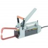
SPOT WELDER
230 VOLT
Model
45690
ASSEMBLY AND OPERATING INSTRUCTIONS
Visit our website at: http://www.harborfreight.com
Read this material before using this product.
Failure to do so can result in serious injury.
SAVE THIS MANUAL.
Copyright
©
2001 by Harbor Freight Tools
®
.
All rights reserved.
No portion of this manual or any artwork
contained herein may be reproduced in any shape or form without the express written consent of Harbor
Freight Tools.
Diagrams within this manual may not be drawn proportionally.
Due to continuing improve-
ments, actual product may differ slightly from the product described herein.
Tools required for assembly
and service may not be included.
For technical questions or replacement parts, please call 1-800-444-3353.