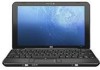
HP 1035nr HP Mini 1000 NetBook - Maintenance and Service Guide
HP 1035nr - Mini - Atom 1.6 GHz Manual
 |
UPC - 884420578406
View all HP 1035nr manuals
Add to My Manuals
Save this manual to your list of manuals |
HP 1035nr manual content summary:
- HP 1035nr | HP Mini 1000 NetBook - Maintenance and Service Guide - Page 1
HP Mini 1000 NetBook Maintenance and Service Guide - HP 1035nr | HP Mini 1000 NetBook - Maintenance and Service Guide - Page 2
in the U.S. and other countries. Microsoft and Windows are U.S. registered trademarks of Microsoft Corporation. SD services. Nothing herein should be construed as constituting an additional warranty. HP shall not be liable for technical or editorial errors or omissions contained herein. First Edition - HP 1035nr | HP Mini 1000 NetBook - Maintenance and Service Guide - Page 3
the device, do not place the device directly on your lap or obstruct the device air vents. Use the device only on a hard, flat surface. Do not allow another hard surface, such as an adjoining optional printer, or a soft surface, such as pillows or rugs or clothing, to block airflow. Also, do - HP 1035nr | HP Mini 1000 NetBook - Maintenance and Service Guide - Page 4
iv Safety warning notice - HP 1035nr | HP Mini 1000 NetBook - Maintenance and Service Guide - Page 5
Top components ...4 Display ...4 Keys ...5 TouchPad ...6 Front components ...7 Right-side components ...8 Left-side Removal and replacement procedures Preliminary replacement requirements 22 Tools required ...22 Service considerations ...22 Plastic parts ...22 Cables and connectors 22 Drive - HP 1035nr | HP Mini 1000 NetBook - Maintenance and Service Guide - Page 6
replacement procedures 28 Service tag ...28 Device feet ...29 Battery ...30 Memory module ...31 Keyboard ...33 Mass storage devices ...35 Top cover ...37 WLAN module ...40 RTC battery Setup Utility 57 Displaying system information 57 Restoring default settings in the Setup Utility 57 Exiting the - HP 1035nr | HP Mini 1000 NetBook - Maintenance and Service Guide - Page 7
Creating recovery points ...81 Scheduling backups ...82 Performing a recovery ...82 Initiating a recovery in Windows 82 9 Connector pin assignments Audio-in (microphone) ...83 Audio-out (headphone) ...83 RJ specific countries and regions 86 11 Recycling Battery ...87 Display ...87 Index ...93 vii - HP 1035nr | HP Mini 1000 NetBook - Maintenance and Service Guide - Page 8
viii - HP 1035nr | HP Mini 1000 NetBook - Maintenance and Service Guide - Page 9
1 Product description Category Product Name Processor Chipset Graphics Panels Memory Mass storage devices Optical drive Diskette drive Audio Description HP Mini 1000 NetBook Intel® Atom™ N270 1.6-GHz processor, 512-KB L2 cache, 533-MHz front-side bus (FSB) Northbridge: 945GSE; 533-MHz bus speed - HP 1035nr | HP Mini 1000 NetBook - Maintenance and Service Guide - Page 10
two-way scrolling (taps enabled as default) Power requirements 30-W UMA AC adapter (non-smart) with localized cable plug support AC adapter connector on cable 3-cell lithium-polymer battery (2.4-Ah, 26-Wh), 3-hour target life Security Supports HP security lock Operating system Preinstalled - HP 1035nr | HP Mini 1000 NetBook - Maintenance and Service Guide - Page 11
Category Serviceability Description Windows® XP Home SP3, ultra low-cost personal computer (ULCPC) edition Restore media: Backup software provided by operating system CD and recovery DVD End-user replaceable parts: AC adapter Battery (system) Memory module 3 - HP 1035nr | HP Mini 1000 NetBook - Maintenance and Service Guide - Page 12
. * The antennae are not visible from the outside of the device. For optimal transmission, keep the areas immediately around the antennae free from obstructions. To see wireless regulatory notices, refer to the section of the Regulatory, Safety and Environmental Notices that applies to your - HP 1035nr | HP Mini 1000 NetBook - Maintenance and Service Guide - Page 13
(3) (4) (5) Component esc key Function keys fn key Windows logo key Windows applications key Function Displays system information when pressed in combination in combination with a function key. Displays the Windows Start menu. Displays a shortcut menu for items beneath the pointer. Top components - HP 1035nr | HP Mini 1000 NetBook - Maintenance and Service Guide - Page 14
or activates items on the screen. Scrolls up or down. Functions like the right button on an external mouse. * This table describes factory settings. To view or change pointing device preferences, select Start > Control Panel > Printers and Other Hardware > Mouse. 6 Chapter 2 External component - HP 1035nr | HP Mini 1000 NetBook - Maintenance and Service Guide - Page 15
> Power Options. Blinking: The hard drive or flash drive is being accessed. ● On: A battery is charging. ● Blinking: A battery that is the only available power source has reached a low battery level. When the battery reaches a critical battery level, the battery light begins blinking rapidly. ● Off - HP 1035nr | HP Mini 1000 NetBook - Maintenance and Service Guide - Page 16
cycle on and off during routine operation. Supports the following optional digital card formats: ● MultiMediaCard (MMC) ● Secure Digital (SD) Memory Card Connects an optional USB device. Connects an optional HP Mini Mobile Drive. Attaches an optional security cable to the device. NOTE: The security - HP 1035nr | HP Mini 1000 NetBook - Maintenance and Service Guide - Page 17
is running on AC power. ● Off: The device is running on battery power. USB port Vent Connects an optional USB device. Enables airflow to routine operation. Expansion port Connects an optional VGA cable, which allows you to connect an external VGA monitor or projector. Audio-out (headphone) - HP 1035nr | HP Mini 1000 NetBook - Maintenance and Service Guide - Page 18
Bottom components Item (1) (2) (3) Component Battery bay Battery release latches (2) Memory module compartment (4) Vent Function Holds the battery. Release the battery from the battery bay. Contains the memory module slot. NOTE: The release latch for the memory module compartment cover (not - HP 1035nr | HP Mini 1000 NetBook - Maintenance and Service Guide - Page 19
the bottom of the device, provides information that may be needed when troubleshooting system problems. The service tag provides the following information: (1) Product name: This is the product name affixed to the front of the device. (2) Serial number (s/n): This is an alphanumeric identifier that - HP 1035nr | HP Mini 1000 NetBook - Maintenance and Service Guide - Page 20
Device major components Item (1) (2) Description Spare part number Display assembly (includes webcam, 1 microphone, and 2 WLAN antenna transceivers/ cables) 8.9-inch WSVGA BrightView 10.2-inch WSVGA AntiGlare Refer to Display assembly components on page 15, for more display assembly component - HP 1035nr | HP Mini 1000 NetBook - Maintenance and Service Guide - Page 21
(includes TouchPad) 504612-001 Mass storage device Hard drive (includes FPC cable and bracket): 60-GB, 4200-rpm 504601-001 Hard Drive Hardware Kit (includes bracket) 504607-001 Solid-state drive (select models only, not illustrated; includes FPC cable and bracket) 16-GB 507314-001 8-GB - HP 1035nr | HP Mini 1000 NetBook - Maintenance and Service Guide - Page 22
Cable Kit, spare part number 507708-001. Base enclosure (includes 4 rubber feet) 506377-001 Memory module (PC2-4200, 533-MHz, DDR2) 1024-MB 504600-001 512-MB 504599-001 Memory module compartment cover (see Plastics Kit on page 16 for spare part number 507317-001 information) Battery 3-cell - HP 1035nr | HP Mini 1000 NetBook - Maintenance and Service Guide - Page 23
Speaker grill (2) Speaker assembly (includes left and right cables) 506338-001 506335-001 (3) Display bezel (for use with 8.9-inch panel only) (4) ; includes LCD cable and foil shield) (7) Display Cable Kit (for 8.9-inch panels only; includes WLAN, microphone cable, and webcam module cable) (8) - HP 1035nr | HP Mini 1000 NetBook - Maintenance and Service Guide - Page 24
illustrated) Plastics Kit Spare part number 509700-001 506334-001 Item Description Plastics Kit: (1) Memory module compartment cover (2) HP Mobile Drive cover (only on models with solid-state drives) (3) Security cable connector Spare part number 507317-001 16 Chapter 3 Illustrated parts catalog - HP 1035nr | HP Mini 1000 NetBook - Maintenance and Service Guide - Page 25
PM2.5×7.0 screw ● Phillips PM2.5×9.0 screw System power printed circuit board (PCB) with USB and SIM VGA Cable Cable Kit ● Bluetooth module cable ● Internal display switch module ● Fan cable ● USB board cable Rubber Kit (contains 4 device feet and RJ-45 cover) Spare part number 496813-001 512852 - HP 1035nr | HP Mini 1000 NetBook - Maintenance and Service Guide - Page 26
bracket (fits over power and USB ports) ● USB connector bracket ● 3G connector bracket ● Actuators for power switch and wireless switch ● Internal display switch bracket HP Mini Mobile Drive (supported on models with HP Mobile Drives) 2-GB 4-GB 8-GB Slip case Spare part number 507318-001 512329 - HP 1035nr | HP Mini 1000 NetBook - Maintenance and Service Guide - Page 27
number listing Spare part number Description 483377-002 HP un2400 Mobile Broadband Module 490371-001 Power webcam module spare part kit does not include a webcam module cable. The webcam module cable is included in the Display Cable Kit, spare part number 504597-001. 504595-001 Display - HP 1035nr | HP Mini 1000 NetBook - Maintenance and Service Guide - Page 28
4200, 533-MHz, DDR2) 504600-001 1024-MB memory module (PC2-4200, 533-MHz, DDR2) 504601-001 60-GB, 4200-rpm hard drive (includes FPC cable and bracket) 504607-001 Hard Drive Hardware Kit (includes bracket) 504610-001 3-cell, 26-Wh Li-Pol battery for use in all countries and regions except Germany - HP 1035nr | HP Mini 1000 NetBook - Maintenance and Service Guide - Page 29
-001. RTC battery Cable Kit 8.9-inch WSVGA BrightView display panel (includes LCD cable and foil shield) Display Rubber Kit (for 8.9-inch panels only) Display Screw Kit (for 8.9-inch panels only) VGA Cable Slip case HP Mini Mobile Drive, 2-GB HP Mini Mobile Drive, 4-GB HP Mini Mobile Drive, 8-GB 30 - HP 1035nr | HP Mini 1000 NetBook - Maintenance and Service Guide - Page 30
Using excessive force during disassembly and reassembly can damage plastic parts. Use care when handling the plastic parts. Apply pressure only at the points designated in the maintenance instructions. Cables and connectors CAUTION: When servicing the device, be sure that cables are placed in their - HP 1035nr | HP Mini 1000 NetBook - Maintenance and Service Guide - Page 31
with at least one inch of shock-proof foam. Avoid dropping drives from any height onto any surface. After removing a hard drive, an optical drive, or a diskette drive, place it in a static-proof bag. Avoid exposing a hard drive to products that have magnetic fields, such as monitors or speakers - HP 1035nr | HP Mini 1000 NetBook - Maintenance and Service Guide - Page 32
life expectancy. CAUTION: To prevent damage to the device when you are removing or installing internal components, observe these precautions: Keep components in their electrostatic ,000 V 55% 7,500 V 3,000 V 400 V 400 V 2,000 V 3,500 V 7,000 V 5,000 V 24 Chapter 4 Removal and replacement procedures - HP 1035nr | HP Mini 1000 NetBook - Maintenance and Service Guide - Page 33
-free workstations. ● Place items on a grounded surface before removing equipment. ● Use conductive field service tools, such as cutters, screwdrivers . ● Keep the work area free of nonconductive materials, such as these items only at static-free workstations. ● Avoid contact with pins, - HP 1035nr | HP Mini 1000 NetBook - Maintenance and Service Guide - Page 34
of one megohm resistance ● Static-dissipative tables or floor mats with hard ties to the ground ● Field service kits ● Static awareness labels ● Material-handling packages ● Nonconductive plastic mats Voltage protection level 1,500 V 7,500 V 5,000 V 26 Chapter 4 Removal and replacement procedures - HP 1035nr | HP Mini 1000 NetBook - Maintenance and Service Guide - Page 35
5. Remove the real-time clock (RTC) battery (see RTC battery on page 42). 6. Wait approximately 5 minutes. 7. Replace the RTC battery and reassemble the device. 8. Connect AC power to the device. Do not reinsert any batteries at this time. 9. Turn on the device. All passwords and all CMOS settings - HP 1035nr | HP Mini 1000 NetBook - Maintenance and Service Guide - Page 36
special note of each screw size and location during removal and replacement. Service tag The service tag, affixed to the bottom of the device, provides information that may be needed when troubleshooting system problems. The service tag provides the following information: (1) Product name: This is - HP 1035nr | HP Mini 1000 NetBook - Maintenance and Service Guide - Page 37
Device feet The device feet are adhesive-backed rubber pads. The feet are included in the Rubber Kit, spare part number 504613-001. There are 4 rubber feet that are installed on the base enclosure in the locations illustrated below. Component replacement procedures 29 - HP 1035nr | HP Mini 1000 NetBook - Maintenance and Service Guide - Page 38
(2) and remove the battery (3) from the device. To install the battery, insert the rear edge of the battery into the battery bay and pivot the battery downward until it is seated. The battery release latch automatically locks the battery into place. 30 Chapter 4 Removal and replacement procedures - HP 1035nr | HP Mini 1000 NetBook - Maintenance and Service Guide - Page 39
device by first unplugging the power cord from the AC outlet and then unplugging the AC adapter from the device. 4. Remove the battery (see Battery on page 30). Remove the memory module: 1. Slide the right battery release latch to the inside or "unlocked" position to reveal the release latch for the - HP 1035nr | HP Mini 1000 NetBook - Maintenance and Service Guide - Page 40
4. Remove the memory module (2) by pulling the module away from the slot at an angle. NOTE: Memory modules are designed with a notch (3) to prevent incorrect insertion into the memory module slot. Reverse this procedure to install a memory module. 32 Chapter 4 Removal and replacement procedures - HP 1035nr | HP Mini 1000 NetBook - Maintenance and Service Guide - Page 41
on page 30). Remove the keyboard: 1. Remove the black Phillips PM2.0×4.0 screw (on the back wall of the battery bay) that secures the keyboard to the device. 2. Turn the device display-side up, with the front toward you. 3. Open the device as far as possible. Component replacement procedures 33 - HP 1035nr | HP Mini 1000 NetBook - Maintenance and Service Guide - Page 42
then slide it back (3) until it rests on the display assembly. 5. Release the zero insertion force (ZIF) connector (1) to which the keyboard cable is attached, and then disconnect the cable (2) from the system board. 6. Remove the keyboard. Reverse this procedure to install the keyboard. 34 Chapter - HP 1035nr | HP Mini 1000 NetBook - Maintenance and Service Guide - Page 43
from the device. 4. Remove the battery (see Battery on page 30). 5. Remove the keyboard (see Keyboard on page 33). To remove the hard drive: 1. Release the ZIF connector (1) to which the USB board pass-through cable is attached. The cable lies across the top of the hard drive. 2. Disconnect the USB - HP 1035nr | HP Mini 1000 NetBook - Maintenance and Service Guide - Page 44
up (4), and then slide it out of the drive bay. Reverse this procedure to install the hard drive. To remove the solid-state drive: 1. Release the ZIF connector (1) to which the USB board pass-through cable (that lies across the top of the drive) is attached. 2. Disconnect the USB board pass-through - HP 1035nr | HP Mini 1000 NetBook - Maintenance and Service Guide - Page 45
outlet and then unplugging the AC adapter from the device. 4. Remove the battery (see Battery on page 30). 5. Remove the keyboard (see Keyboard on page 33). 6. Remove the hard drive or solid-state drive (see Mass storage devices on page 35). Remove the top cover: 1. Turn the device upside down, with - HP 1035nr | HP Mini 1000 NetBook - Maintenance and Service Guide - Page 46
a rounded square: ● The two front covers are short in height and are is taller in height and is not notched. 3. Remove the four black Phillips PM2.5×9.0 screws (2) that secure the top side up, with the front toward you. 5. Open the device as far as possible. 6. Remove the black Phillips PM2.0×7.0 - HP 1035nr | HP Mini 1000 NetBook - Maintenance and Service Guide - Page 47
it back slightly to rest against the display assembly at an angle (2). 8. Release the ZIF connector (1) to which the TouchPad button board cable is connected, and then disconnect the cable (2) from the system board. 9. Remove the top cover. Reverse this procedure to install the top cover. Component - HP 1035nr | HP Mini 1000 NetBook - Maintenance and Service Guide - Page 48
the battery (see Battery on page 30). 5. Remove the following components: a. Keyboard (see Keyboard on page 33) b. Hard drive or solid-state drive (see Mass storage devices on page 35) c. Top cover (see Top cover on page 37) Remove the WLAN module: 40 Chapter 4 Removal and replacement procedures - HP 1035nr | HP Mini 1000 NetBook - Maintenance and Service Guide - Page 49
devices in your country or region. If you replace the module and then receive a warning message, remove the module to restore device functionality, and then contact technical support through Help and Support. 1. Disconnect the wireless antenna cables (1) from the terminals on the WLAN module - HP 1035nr | HP Mini 1000 NetBook - Maintenance and Service Guide - Page 50
a. Keyboard (see Keyboard on page 33) b. Hard drive or solid-state drive (see Mass storage devices on page 35) c. Top cover (see Top cover on page 37) Remove the RTC battery: 1. Disconnect the RTC battery cable (1) from the system board. 2. Detach the RTC battery (2) from the system board, and then - HP 1035nr | HP Mini 1000 NetBook - Maintenance and Service Guide - Page 51
from the AC outlet and then unplugging the AC adapter from the device. 4. Remove the battery (see Battery on page 30). 5. Remove the following components: a. Keyboard (see Keyboard on page 33) b. Hard drive or solid-state drive (see Mass storage devices on page 35) c. Top cover (see Top cover on - HP 1035nr | HP Mini 1000 NetBook - Maintenance and Service Guide - Page 52
(see Battery on page 30). 5. Remove the following components: a. Keyboard (see Keyboard on page 33) b. Hard drive or solid-state drive (see Mass storage devices on page 35) c. Top cover (see Top cover on page 37) When replacing the system board, be sure that the following components are removed from - HP 1035nr | HP Mini 1000 NetBook - Maintenance and Service Guide - Page 53
from the system board: (1) Speaker cables (2) Microphone cable (3) Fan cable (4) Display panel cable NOTE: The USB board pass-through cable (5) was disconnected earlier (see Mass storage devices on page 35). 3. Remove the two silver Phillips PM2.0×3.0 screws (1) that secure the actuators for the - HP 1035nr | HP Mini 1000 NetBook - Maintenance and Service Guide - Page 54
that secure the USB connector bracket to the base enclosure, and then remove the bracket (2). NOTE: The USB connector bracket is included in the the right side up (2). 6. Remove the system board (3). Reverse the procedure to install the system board. 46 Chapter 4 Removal and replacement procedures - HP 1035nr | HP Mini 1000 NetBook - Maintenance and Service Guide - Page 55
from the AC outlet and then unplugging the AC adapter from the device. 4. Remove the battery (see Battery on page 30). 5. Remove the following components: a. Keyboard (see Keyboard on page 33) b. Hard drive or solid-state drive (see Mass storage devices on page 35) c. Top cover (see Top cover on - HP 1035nr | HP Mini 1000 NetBook - Maintenance and Service Guide - Page 56
cable. The fan cable is included in the Cable Kit, spare part number 507708-001. Description Fan Spare part number 504615-001 Before removing Remove the battery (see Battery on page 30). 5. Remove the following components: a. Keyboard (see Keyboard on page 33) b. Hard drive or solid-state drive - HP 1035nr | HP Mini 1000 NetBook - Maintenance and Service Guide - Page 57
device. 4. Remove the battery (see Battery on page 30). 5. Remove the following components: a. Keyboard (see Keyboard on page 33) b. Hard drive or solid-state drive (see Mass storage devices on page 35) c. Top cover (see Top cover on page 37) Remove the display assembly: CAUTION: Support the display - HP 1035nr | HP Mini 1000 NetBook - Maintenance and Service Guide - Page 58
2. Lift the display assembly (2) straight up and remove it. 3. If it is necessary to replace the speakers, perform the following steps: a. Squeeze the sides of the speaker grill together to release the pressure clips, and then remove the speaker grill. The speaker grill is available using spare part - HP 1035nr | HP Mini 1000 NetBook - Maintenance and Service Guide - Page 59
is available using spare part number 506335-001. 4. If it is necessary to replace the display hinges, remove the two silver Phillips PM2.0×6.0 screws (1) that secure each hinge to the display enclosure, and then remove the hinges (2). The hinges (for 8.9-inch panels only) are available in the - HP 1035nr | HP Mini 1000 NetBook - Maintenance and Service Guide - Page 60
then remove the display bezel (4). The display bezel, spare part number 506333-001, is for use with 8.9-inch panel only. 6. If it is necessary to replace the webcam module, perform the following steps: a. Open the tab built into the display enclosure shielding that secures the microphone cable, and - HP 1035nr | HP Mini 1000 NetBook - Maintenance and Service Guide - Page 61
number 504594-001. 7. If it is necessary to replace the display panel, perform the following steps: a. Remove the eight black Phillips PM2.0×4.0 screws that secure the display panel to the display enclosure. b. Remove the wireless antenna cables (1) from the clips and routing channels built into - HP 1035nr | HP Mini 1000 NetBook - Maintenance and Service Guide - Page 62
display panel from the display enclosure (3). An 8.9-inch display panel (includes LCD cable and foil shield) is available as spare part number 508968-001. 8. If it is necessary to replace the display panel brackets, remove the two black Phillips PM2.0×4.0 screws (1) that secure each bracket to the - HP 1035nr | HP Mini 1000 NetBook - Maintenance and Service Guide - Page 63
it is necessary to replace the wireless antenna transceivers and cables, detach the adhesive that secures the cables to the display enclosure, and then remove the cables. The wireless antenna transceivers and cables (for 8.9-inch panels only) are available in the Display Cable Kit, spare part number - HP 1035nr | HP Mini 1000 NetBook - Maintenance and Service Guide - Page 64
used even when your Windows operating system is , and then press f10 while the "F10 = BIOS Setup Options" message is displayed in the lower-left enter. 3. Use the arrow keys to select a language, and then press enter. 4. When a confirmation prompt with your language selected is displayed, press enter - HP 1035nr | HP Mini 1000 NetBook - Maintenance and Service Guide - Page 65
Because the Setup Utility is not Windows based, it does not support the TouchPad. Navigation and selection are enter. The Setup Utility default settings go into effect when the device restarts. NOTE: Your password, security, and language settings are not changed when you restore the factory default - HP 1035nr | HP Mini 1000 NetBook - Maintenance and Service Guide - Page 66
the device. ● View specification information about the processor, memory size, and system BIOS. Security menu Select Administrator password Power-on password To do this Enter, change, or delete an administrator password. Enter, change, or delete a power-on password. 58 Chapter 5 Setup Utility - HP 1035nr | HP Mini 1000 NetBook - Maintenance and Service Guide - Page 67
System Configuration menu Select Language Support Processor C4 State Boot Options hard drive (select models only) ◦ USB Floppy ◦ USB CD/DVD ROM Drive ◦ USB Diskette on Key ◦ USB Hard drive ◦ USB Card Reader ◦ Network adapter Diagnostics menu Select Hard Disk Self Test (select models only) Memory - HP 1035nr | HP Mini 1000 NetBook - Maintenance and Service Guide - Page 68
a 3-cell battery, 60-GB hard drive, 1.08 kg 1-GB memory, WLAN module, and 2 wireless antennae 8.9-in. LCD, equipped with a 3-cell battery, 8-GB solid-state 1.02 kg drive, 1-GB memory, WLAN module, and 2 wireless antennae 2.40 lbs 2.38 lbs 2.25 lbs Input power Operating voltage Operating current - HP 1035nr | HP Mini 1000 NetBook - Maintenance and Service Guide - Page 69
8.9-inch, WSVGA display specifications Dimensions Height Width Diagonal Number of colors Contrast ratio Brightness Pixel resolution Pitch Format Configuration Backlight Character display Total power consumption Viewing angle Metric U.S. 11.34 cm 19.51 22.61 cm 262,144 300:1 (typical) 200 nits ( - HP 1035nr | HP Mini 1000 NetBook - Maintenance and Service Guide - Page 70
10.2-inch, WSVGA display specifications Dimensions Height Width Diagonal Number of colors Contrast ratio Brightness Pixel resolution Pitch Format Configuration Backlight Character display Total power consumption Viewing angle Metric U.S. 12.53 cm 22.27 cm 25.55 cm 262,144 400:1 (typical) 200 - HP 1035nr | HP Mini 1000 NetBook - Maintenance and Service Guide - Page 71
Operating temperature *1 GB = 1 billion bytes when referring to hard drive storage capacity. Actual accessible capacity is less. Actual drive specifications may differ slightly. NOTE: Certain restrictions and exclusions apply. Contact technical support for details. Hard drive specifications 63 - HP 1035nr | HP Mini 1000 NetBook - Maintenance and Service Guide - Page 72
Solid-state drive specifications Performance Transfer modes supported Sustained read Sustained write Characteristics Interface MLC NAND flash capacity Electrical specifications DC supply voltage Standby current Active current Environmental specifications Operating temperature Storage temperature - HP 1035nr | HP Mini 1000 NetBook - Maintenance and Service Guide - Page 73
applicable Not applicable Direct memory access controller System Default configuration System function System timer Standard 101-/102-Key or Microsoft® Natural PS/2 Keyboard System CMOS USB Universal Host Controller-27CB Microsoft UAA Bus Driver for High Definition Audio Mobile Intel 945 Express - HP 1035nr | HP Mini 1000 NetBook - Maintenance and Service Guide - Page 74
101-/102-Key or Microsoft Natural PS/2 Keyboard Motherboard resources Microsoft ACPI-Compliant Embedded Controller Motherboard resources System CMOS/real-time clock Motherboard resources Motherboard resources DMA controller Motherboard resources DMA controller Motherboard resources DMA controller - HP 1035nr | HP Mini 1000 NetBook - Maintenance and Service Guide - Page 75
I/O address (hex) 279 - 279 3B0 - 3BB 3C0 - 3DF 3F6 - 3F6 400 - 41F 480 - 4BF 4D0 - 4D1 500 - 501 800 - 87F A79 - A79 0D00 - FFFF D480 - D49F D800 - D81F D880 - D89F DC00 - DC1F DC80 - DC87 E000 - EFFF FFA0 - FFAF System function (shipping configuration) ISAPNP Read Data Port Mobile Intel® 945 - HP 1035nr | HP Mini 1000 NetBook - Maintenance and Service Guide - Page 76
System memory map specifications Memory address 00000000 - 0009FFFF 000A0000 - 000BFFFF 000A0000 - 000BFFFF 000C0000 - 000CFFFF 000D0000 - 82801G (ICH7 Family) USB2 Enhanced Host Controller-27CC Microsoft® UAA Bus Driver for High Definition Audio Mobile Intel 945 Express Chipset Family Mobile Intel - HP 1035nr | HP Mini 1000 NetBook - Maintenance and Service Guide - Page 77
7 Screw listing This section provides specification and reference information for the screws and screw locks used in the device. All screws listed in this section are available in the Screw Kit, spare part number 504614-001, or in the Display Screw Kit, part number 509700-001. Phillips PM1.6×2.5 - HP 1035nr | HP Mini 1000 NetBook - Maintenance and Service Guide - Page 78
screw Color Silver Quantity 3 (hard-drive option) 5 (SSD option) Length 3.0 mm Thread 2.0 mm Head diameter 4.5 mm Where used: Two screws that secure the power and wireless switch actuators to the system board Where used: Two screws that secure the solid-state drive bracket to the device 70 - HP 1035nr | HP Mini 1000 NetBook - Maintenance and Service Guide - Page 79
Where used: One screw that secures the WLAN module to the system board Phillips PM2.0×4.0 screw Color Silver Quantity 19 Length 4.0 mm Thread 2.0 mm Head diameter 4.5 mm Where used: One screw that secures the keyboard to the device Phillips PM2.0×4.0 screw 71 - HP 1035nr | HP Mini 1000 NetBook - Maintenance and Service Guide - Page 80
Where used: Two screws that secure the USB connector bracket to the system board Where used: Two screws that secure the webcam module to the display enclosure Where used: Eight screws that secure the display panel to the display enclosure 72 Chapter 7 Screw listing - HP 1035nr | HP Mini 1000 NetBook - Maintenance and Service Guide - Page 81
Where used: Four screws that secure the left and right display panel brackets to the display panel Where used: Two screws that secure the fan to the base enclosure Phillips PM2.0×4.0 screw 73 - HP 1035nr | HP Mini 1000 NetBook - Maintenance and Service Guide - Page 82
Phillips PM2.0×6.0 screw Color Black Quantity 6 (hard-drive option) 4 (SSD option) Length 6.0 mm Thread 2.0 mm Head diameter 4.5 mm Where used: Two screws that secure the hard drive to the system board Where used: Four screws that secure the display hinges to the display assembly 74 Chapter 7 - HP 1035nr | HP Mini 1000 NetBook - Maintenance and Service Guide - Page 83
Phillips PM2.0×7.0 screw Color Silver Quantity 1 Length 7.0 mm Thread 2.0 mm Head diameter 4.5 mm Where used: One screw that secures the top cover to the device (top console) Phillips PM2.0×7.0 screw 75 - HP 1035nr | HP Mini 1000 NetBook - Maintenance and Service Guide - Page 84
Phillips PM2.0×8.0 screw Color Silver Quantity 2 Length 8.0 mm Thread 2.0 mm Head diameter 4.5 mm Where used: Two screws that secure the speaker assembly to the display enclosure 76 Chapter 7 Screw listing - HP 1035nr | HP Mini 1000 NetBook - Maintenance and Service Guide - Page 85
Phillips PM2.5×7.0 screw Color Silver Quantity 4 Length 7.0 mm Thread 2.5 mm Head diameter 5.0 mm Where used: Four screws that secure the display assembly to the device Phillips PM2.5×7.0 screw 77 - HP 1035nr | HP Mini 1000 NetBook - Maintenance and Service Guide - Page 86
Phillips PM2.5×9.0 screw Color Silver Quantity 4 Length 9.0 mm Thread 2.5 mm Head diameter 5.0 mm Where used: Four screws that secure the base enclosure to the device 78 Chapter 7 Screw listing - HP 1035nr | HP Mini 1000 NetBook - Maintenance and Service Guide - Page 87
NOTE: You can recover only the files that you have previously backed up. HP recommends that you use the Windows backup utility to create a hard drive backup as soon as you set up your device. With the Windows backup utility, you can perform the following tasks: ● Backing up your information - HP 1035nr | HP Mini 1000 NetBook - Maintenance and Service Guide - Page 88
an optional external hard drive or to a network drive. NOTE: This process will take several minutes, depending on the file size and the speed of the device. To back up individual files or folders: 1. Select Start > All Programs > Accessories > System Tools > Backup. The Backup or Restore Wizard page - HP 1035nr | HP Mini 1000 NetBook - Maintenance and Service Guide - Page 89
: A copy of the backup files can be stored on an optional external hard drive or on a network drive. To back up all files and folders: 1. Select Start > All Programs > Accessories > System Tools > Backup. The Backup or Restore Wizard page opens. 2. Click Next. 3. Click Backup files and settings, and - HP 1035nr | HP Mini 1000 NetBook - Maintenance and Service Guide - Page 90
a recovery in Windows, follow these steps: 1. If possible, back up all personal files. 2. Select Start > All Programs > Accessories > System Tools > Backup. The Backup or Restore Wizard page opens. 3. Click Restore files and settings, and then click Next. 4. Follow the on-screen instructions. 82 - HP 1035nr | HP Mini 1000 NetBook - Maintenance and Service Guide - Page 91
9 Connector pin assignments Audio-in (microphone) Pin Signal 1 Audio signal in 2 Audio signal in 3 Ground Audio-out (headphone) Pin Signal 1 Audio out, left channel 2 Audio out, right channel 3 Ground Audio-in (microphone) 83 - HP 1035nr | HP Mini 1000 NetBook - Maintenance and Service Guide - Page 92
RJ-45 (network) Pin Signal 1 Transmit + 2 Transmit - 3 Receive + 4 Unused 5 Unused 6 Receive - 7 Unused 8 Unused Universal Serial Bus Pin Signal 1 +5 VDC 2 Data - 3 Data + 4 Ground 84 Chapter 9 Connector pin assignments - HP 1035nr | HP Mini 1000 NetBook - Maintenance and Service Guide - Page 93
accredited agency responsible for evaluation in the country or region where the power cord set will be used. ● The power cord sets must have a minimum current capacity of 10 amps and a nominal voltage rating of 125 or 250 V AC, as required by the power system of each country or region. ● The - HP 1035nr | HP Mini 1000 NetBook - Maintenance and Service Guide - Page 94
Requirements for specific countries and regions Country/region Accredited agency Applicable note number Australia EANSW 1 Austria OVE 1 Belgium CEBC 1 Canada CSA 2 Denmark DEMKO 1 Finland FIMKO 1 France UTE 1 Germany VDE 1 Italy IMQ 1 Japan METI 3 The Netherlands - HP 1035nr | HP Mini 1000 NetBook - Maintenance and Service Guide - Page 95
area for computer battery disposal. Display WARNING! The backlight contains mercury. Exercise caution when removing and handling the disassembly instructions for the display assembly. The display assembly must be disassembled to gain access to the backlight (1) and the liquid crystal display (LCD - HP 1035nr | HP Mini 1000 NetBook - Maintenance and Service Guide - Page 96
steps to disassemble the display assembly: 1. Remove all screw covers (1) and screws (2) that secure the display bezel to the display assembly. 2. Lift up and out on the left and right inside edges (1) and the top and bottom inside edges (2) of the display bezel until the bezel disengages from - HP 1035nr | HP Mini 1000 NetBook - Maintenance and Service Guide - Page 97
4. Disconnect all display panel cables (1) from the display inverter and remove the inverter (2). 5. Remove all screws (1) that secure the display panel assembly to the display enclosure. 6. Remove the display panel assembly (2) from the display enclosure. 7. Turn the display panel assembly upside - HP 1035nr | HP Mini 1000 NetBook - Maintenance and Service Guide - Page 98
the display panel frame (2) from the display panel. 11. Remove the screws (1) that secure the backlight cover to the display panel. 12. Lift the top edge of the backlight cover (2) and swing it outward. 13. Remove the backlight cover. 14. Turn the display panel right-side up. 90 Chapter 11 Recycling - HP 1035nr | HP Mini 1000 NetBook - Maintenance and Service Guide - Page 99
15. Remove the backlight cables (1) from the clip (2) in the display panel. 16. Turn the display panel upside down. WARNING! The backlight contains mercury. Exercise caution when removing and handling the backlight to avoid damaging this component and causing exposure to the mercury. 17. Remove the - HP 1035nr | HP Mini 1000 NetBook - Maintenance and Service Guide - Page 100
backlight frame. 19. Disconnect the display panel cable (1) from the LCD panel. 20. Remove the screws (2) that secure the LCD panel to the display rear panel. 21. Release the LCD panel (3) from the display rear panel. 22. Release the tape (4) that secures the LCD panel to the display rear panel. 23 - HP 1035nr | HP Mini 1000 NetBook - Maintenance and Service Guide - Page 101
9 service considerations 22 D device feet locations 29 spare part number 29 device specifications 60 diskette drive precautions 23 product description 1 display assembly removal 49 spare part number 12, 20, 49 display bezel illustrated 15 removal 52 spare part number 15, 20, 52 Display Cable Kit - HP 1035nr | HP Mini 1000 NetBook - Maintenance and Service Guide - Page 102
Windows applications 5 Windows logo 5 H hard drive precautions 23 product description 1 removal 35 spare part number 13, 20, 35 specifications 63 Hard Drive Hardware Kit, spare part number 13, 20 headphone jack location 9 pin assignments 83 heat sink assembly removal 47 spare part number 47 HP Mini - HP 1035nr | HP Mini 1000 NetBook - Maintenance and Service Guide - Page 103
2 power requirements 2 processors 1 product name 1 security 2 serviceability 3 solid-state drive 1 webcam 2 wireless 2 product name 1 R removal/replacement preliminaries 22 procedures 28 right-side components 8 RJ-45 jack location 9 pin assignments 84 RTC battery removal 42 spare part number 13, 21 - HP 1035nr | HP Mini 1000 NetBook - Maintenance and Service Guide - Page 104
removal 55 spare part number 15, 55 WLAN module removal 40 spare part number 13, 19, 40 workstation guidelines 25 96 Index - HP 1035nr | HP Mini 1000 NetBook - Maintenance and Service Guide - Page 105
-
 1
1 -
 2
2 -
 3
3 -
 4
4 -
 5
5 -
 6
6 -
 7
7 -
8
-
9
-
10
-
11
-
12
-
13
-
14
-
15
-
16
-
17
-
18
-
19
-
20
-
21
-
22
-
23
-
24
-
25
-
26
-
27
-
28
-
29
-
30
-
31
-
32
-
33
-
34
-
35
-
36
-
37
-
38
-
39
-
40
-
41
-
42
-
43
-
44
-
45
-
46
-
47
-
48
-
49
-
50
-
51
-
52
-
53
-
54
-
55
-
56
-
57
-
58
-
59
-
60
-
61
-
62
-
63
-
64
-
65
-
66
-
67
-
68
-
69
-
70
-
71
-
72
-
73
-
74
-
75
-
76
-
77
-
78
-
79
-
80
-
81
-
82
-
83
-
84
-
85
-
86
-
87
-
88
-
89
-
90
-
91
-
92
-
93
-
94
-
95
-
96
-
97
-
98
-
99
-
100
-
101
-
102
-
103
-
104
-
105
 |
 |

HP Mini 1000 NetBook
Maintenance and Service Guide