HP 262586-B21 HP IP Console Switch User Guide
HP 262586-B21 - IP Console Switch 3x1x16 KVM Manual
 |
UPC - 613326254141
View all HP 262586-B21 manuals
Add to My Manuals
Save this manual to your list of manuals |
HP 262586-B21 manual content summary:
- HP 262586-B21 | HP IP Console Switch User Guide - Page 1
HP IP Console Switch User Guide June 2003 (Second Edition) Part Number 263924-002 - HP 262586-B21 | HP IP Console Switch User Guide - Page 2
to change without notice. The warranties for HP products are set forth in the express limited warranty statements accompanying such products. Nothing herein should be construed as constituting an additional warranty. HP IP Console Switch User Guide June 2003 (Second Edition) Part Number 263924 - HP 262586-B21 | HP IP Console Switch User Guide - Page 3
Reseller xiii Reader's Comments ...xiii Chapter 1 Overview Features ...1-2 Benefits...1-3 IP Console Switch Components 1-4 Chapter 2 Installing the IP Console Switch Installation Checklist...2-2 Kit Contents ...2-2 Required Tool ...2-2 Optional Items...2-2 HP IP Console Switch User Guide iii - HP 262586-B21 | HP IP Console Switch User Guide - Page 4
Status of your IP Console Switch System 6-3 Selecting Servers ...6-4 Soft Switching...6-5 Configuring Servers for Soft Switching 6-5 Soft Switching Servers 6-5 Using Basic OSD Navigation 6-6 Configuring the OSD Setup Menu 6-8 Accessing the Setup Menu 6-9 iv HP IP Console Switch User Guide - HP 262586-B21 | HP IP Console Switch User Guide - Page 5
Scan List 6-24 Starting Scan Mode 6-25 Stopping Scan Mode 6-25 Setting Local Console Switch Security 6-25 Accessing the Security Dialog Box 6-26 Changing the Password 6-27 Setting Password 6-32 Viewing Current User Connections 6-32 Disconnecting a User 6-33 HP IP Console Switch User Guide v - HP 262586-B21 | HP IP Console Switch User Guide - Page 6
IP Console Switch 7-6 Updating the IP Console Switch Hardware 7-6 Updating the IP Console Switch through the IP Console Viewer 7-12 Establishing LAN Connections 7-16 Upgrading FLASH Firmware 7-16 Analyzing FLASH Failures 7-18 Upgrading Interface Adapter Firmware 7-19 Chapter 8 Troubleshooting - HP 262586-B21 | HP IP Console Switch User Guide - Page 7
...A-6 BSMI Notice...A-6 Appendix B Electrostatic Discharge Preventing Electrostatic Damage B-1 Grounding Methods To Prevent Electrostatic Damage B-2 Appendix C Power Cord Set Requirements General Requirements ...C-1 Country-Specific Requirements C-2 Index HP IP Console Switch User Guide vii - HP 262586-B21 | HP IP Console Switch User Guide - Page 8
step instructions for installation and reference information for operation, troubleshooting, and upgrades for the HP IP Console Switch. Audience Assumptions This guide is for the person who installs, administers, and troubleshoots IP Console Switches. HP assumes you are qualified in the servicing of - HP 262586-B21 | HP IP Console Switch User Guide - Page 9
indicates the presence of electric shock hazards. The area contains no user- or field-serviceable parts. Do not open for any reason. WARNING: To reduce the risk of injury occupational health and safety requirements and guidelines for manual material handling. x HP IP Console Switch User Guide - HP 262586-B21 | HP IP Console Switch User Guide - Page 10
extended for any reason. Symbols in Text These symbols can be found in the text of this guide. They have the following meanings. WARNING: Text set off in this manner indicates that failure information to emphasize or supplement important points of the main text. HP IP Console Switch User Guide xi - HP 262586-B21 | HP IP Console Switch User Guide - Page 11
, refer to the HP IP Console Switch Software Guide. Getting Help If you have a problem and have exhausted the information in this guide, you can get further information and other help in the following locations. Technical Support In North America, call the HP Technical Support Phone Center at 1-800 - HP 262586-B21 | HP IP Console Switch User Guide - Page 12
1-800-345-1518. • In Canada, call 1-800-263-5868. • Elsewhere, see the HP website for locations and telephone numbers. Reader's Comments HP welcomes your comments on this guide. Please send your comments and suggestions by email to [email protected]. HP IP Console Switch User Guide xiii - HP 262586-B21 | HP IP Console Switch User Guide - Page 13
Console Switch uses Ethernet networking infrastructure and TCP/IP protocol to transmit KVM information between operators and connected computers. Although 10Base-T Ethernet can be used, HP recommends a dedicated, switched 100Base-T network for improved performance. HP IP Console Switch User Guide - HP 262586-B21 | HP IP Console Switch User Guide - Page 14
, Dutch, German, Italian, and Japanese • Support for 10/100 NIC ports • Application clients that manage 25 IP Console Switches with 512 target devices • 1U form with the ability to mount in a 0U side-mount configuration, as well as behind HP rack-mount keyboards 1-2 HP IP Console Switch User Guide - HP 262586-B21 | HP IP Console Switch User Guide - Page 15
a user running the IP Console Viewer. - User can be located anywhere a valid network connection exists. • Integration with existing HP and Compaq KVM switches, adding IP access NOTE: The HP IP Console Switch is not compatible with HP classic analog KVM switches. HP IP Console Switch User Guide 1-3 - HP 262586-B21 | HP IP Console Switch User Guide - Page 16
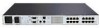
Item Description 1 Power connector 2 Power switch 3 Activity indicator 4 Serial download connector 5 Monitor connector for local user 6 Keyboard connector for local user 7 Mouse connector for local user 8 LAN connector 9 Server connection ports 1-4 HP IP Console Switch User Guide - HP 262586-B21 | HP IP Console Switch User Guide - Page 17
6 7 8 9 10 11 12 13 14 15 16 3 A 1 567 2 4 Figure 1-2: Example of an IP Console Switch configuration A 1 Item Description 1 CPU 2 IP Console Switch 3 Interface Adapter 4 Network 5 Keyboard connector 6 Mouse connector 7 Video connector HP IP Console Switch User Guide 1-5 - HP 262586-B21 | HP IP Console Switch User Guide - Page 18
Console Switch. The IP Console Viewer enables you to view and control a server attached to the console switch system, configure and maintain the system, and prevent unauthorized access to the console switch through IP connection. For more information, refer to the HP IP Console Switch Software Guide - HP 262586-B21 | HP IP Console Switch User Guide - Page 19
• IP Console Switch • Power cords • Rack mounting kit • Download serial cable • Documentation kit • Firmware/software CD • CAT5 crossover cable Required Tool You need a Phillips screwdriver. Optional Items • Expansion Module • Interface Adapter • UTP CAT5 cable 2-2 HP IP Console Switch User Guide - HP 262586-B21 | HP IP Console Switch User Guide - Page 20
the troubleshooting chapter in this guide. Three different rack-mounting configurations are described in the sections below: • Side mount 0U - Type A-Square and round internal mounting rail holes - Type B-Square internal mounting rail holes • Rear rack mount • Standard 1U mount HP IP Console Switch - HP 262586-B21 | HP IP Console Switch User Guide - Page 21
Switch Using Side Mount 0U Installation Type A To side mount the IP Console Switch: 1. Attach the side-mounting brackets to the console switch, using two screws on each side. Figure 2-1: Attaching the side-mounting brackets 10 9 12 11 14 13 16 15 21 43 65 87 2-4 HP IP Console Switch User Guide - HP 262586-B21 | HP IP Console Switch User Guide - Page 22
each side of the rack. 10 9 12 11 14 13 16 15 21 43 65 87 Figure 2-2: Sliding the tabs into the rack 3. Secure the console switch to the rack frame, using two screws on each side. 10 9 12 11 14 13 16 15 21 43 65 87 Figure 2-3: Securing the console switch HP IP Console Switch User Guide 2-5 - HP 262586-B21 | HP IP Console Switch User Guide - Page 23
the IP Console Switch Type B 1. Attach the side-mounting brackets to the console switch, using two screws on each side. 2. Slide the tabs on the side-mounting brackets into the same U location on each side of the rack. Figure 2-4: Sliding the tabs into the rack 2-6 HP IP Console Switch User Guide - HP 262586-B21 | HP IP Console Switch User Guide - Page 24
16 15 21 43 65 87 Installing the IP Console Switch 3. Insert four cage nuts into the rack frame in the location of the side-mounting bracket holes. Figure 2-5: Inserting cage nuts 4. Secure the console switch to the rack frame, using two screws on each side. HP IP Console Switch User Guide 2-7 - HP 262586-B21 | HP IP Console Switch User Guide - Page 25
, making it a 0U installation. To install the IP Console Switch in the rear of the rack: 1. Attach the slide rail brackets to the console switch, using two screws on each slide. 100-240V 10 11 12 13 14 15 16 Figure 2-6: Attaching the slide rail brackets 2-8 HP IP Console Switch User Guide - HP 262586-B21 | HP IP Console Switch User Guide - Page 26
, replace only with same type and rating of fuse. 1 2 3 4 5 6 7 8 9 10 11 12 13 14 15 16 Figure 2-8: Securing the slide rail brackets to the rack HP IP Console Switch User Guide 2-9 - HP 262586-B21 | HP IP Console Switch User Guide - Page 27
the template against the front and rear of the rack frame to mark the attachment points for the mounting rails and rear cage nuts. 2-10 HP IP Console Switch User Guide - HP 262586-B21 | HP IP Console Switch User Guide - Page 28
. Figure 2-10: Installing cage nuts 4. Loosely attach the wing nuts (1), and extend the adjustable rail-mounting brackets to the desired length (2). 1 2 Figure 2-11: Adjusting rails HP IP Console Switch User Guide 2-11 - HP 262586-B21 | HP IP Console Switch User Guide - Page 29
Installing the IP Console Switch 5. Tighten the wing nuts slightly to stabilize the adjustable rails during installation. 6. Insert an adjustable rail rail, using one screw for each cage nut previously installed. Figure 2-12: Securing the adjustable rail 2-12 HP IP Console Switch User Guide - HP 262586-B21 | HP IP Console Switch User Guide - Page 30
protection against risk of fire, replace only with same type and rating of fuse. 1 2 3 4 5 6 7 8 9 10 11 12 13 14 15 16 Figure 2-14: Securing the console switch into the rack HP IP Console Switch User Guide 2-13 - HP 262586-B21 | HP IP Console Switch User Guide - Page 31
. 4. Power on the IP Console Switch. The activity indicator on the rear panel powers on. The activity indicator blinks for 30 seconds while performing a self-test. Approximately 10 seconds after it stops blinking, press the Enter key to access the main menu. 2-14 HP IP Console Switch User Guide - HP 262586-B21 | HP IP Console Switch User Guide - Page 32
). Manually change the device type from "dev/modem" to "/dev/ttyS0" and press the Enter key. d. Select Option E (Bps/Par/Bits). The Comm Parameters menu is displayed. e. Select E (Speed 9600 Bps), and press the Enter key. The designation 9600 8N1 is displayed next to Option E. HP IP Console Switch - HP 262586-B21 | HP IP Console Switch User Guide - Page 33
Installing the IP Console Switch f. Select Option F (Hardware Flow Control). Be sure that the Change which setting? menu is configured as follows: A-Serial Device: . h. Scroll down the Configuration menu to the Exit from Minicom option, and press the Enter key. 2-16 HP IP Console Switch User Guide - HP 262586-B21 | HP IP Console Switch User Guide - Page 34
soon as a connection is established, the Main menu for the IP Console Switch is displayed. Follow the on-screen options to configure the IP Console Switch. The IPViewer HyperTerminal menu with six options is displayed. Figure 2-16: IPViewer HyperTerminal menu HP IP Console Switch User Guide 2-17 - HP 262586-B21 | HP IP Console Switch User Guide - Page 35
next procedure. 9. Select Option 3 through 5 from the Terminal Applications menu to finish configuring the console switch for an IP address, Netmask, and Default Gateway. When this configuration is complete, enter 0 to return to the IPViewer HyperTerminal menu. 2-18 HP IP Console Switch User Guide - HP 262586-B21 | HP IP Console Switch User Guide - Page 36
optimum mouse performance, refer to the "Setting the Mouse Scaling" and "Aligning and Resetting the Mouse" sections in the HP IP Console Switch Software Guide, included on the Rack Products Documentation CD. For Windows operating systems (default drivers): 1. From the desktop, select Start, Settings - HP 262586-B21 | HP IP Console Switch User Guide - Page 37
the IP Console Switch from the analog station. For detailed instructions on OSD setup and configuration, refer to Chapter 6 in this guide. 2. After you install the IP Console Viewer on each digital station, launch the IP Console Viewer and click Add Console Switch to add the new IP Console Switch - HP 262586-B21 | HP IP Console Switch User Guide - Page 38
for eight Interface Adapters • An active KVM connection between one IP Console Switch port and one Interface Adapter at a time • No external power required • Ability to mount along the sides or along the rear of standard 19-inch internal mounting rails HP IP Console Switch User Guide 3-1 - HP 262586-B21 | HP IP Console Switch User Guide - Page 39
11 12 13 14 15 16 3 4 5 6 Figure 3-1: Example of an IP Console Switch configuration with an Expansion Module Item Description 1 IP Console Switch 2 Expansion Module 3 Interface Adapter 4 Video connector 5 Keyboard connector 6 Mouse connector 3-2 HP IP Console Switch User Guide - HP 262586-B21 | HP IP Console Switch User Guide - Page 40
Expansion Module Installing the Expansion Module Hardware Performing a Side-Mount Installation To side mount an Expansion Module to the rack: 1. Slide the tabs on the side-mounting brackets into the rack frame. Figure 3-2: Sliding the tabs into the rack HP IP Console Switch User Guide 3-3 - HP 262586-B21 | HP IP Console Switch User Guide - Page 41
Expansion Module 2. Secure the Expansion Module to the rack frame, using one self-tapping screw for the bottom side-mounting bracket. Figure 3-3: Inserting screw 3-4 HP IP Console Switch User Guide - HP 262586-B21 | HP IP Console Switch User Guide - Page 42
Expansion Module Performing a Rail-Mount Installation To rail mount an Expansion Module to the rack: 1. Remove screws securing the side-mounting brackets to the Expansion Module. Figure 3-4: Removing screws HP IP Console Switch User Guide 3-5 - HP 262586-B21 | HP IP Console Switch User Guide - Page 43
rack frame where the mounting bracket holes are located (1). Secure the Expansion Module to the rack frame, using two M-6 screws (2). 1 2 1 2 Figure 3-5: Installing the Expansion Module 3-6 HP IP Console Switch User Guide - HP 262586-B21 | HP IP Console Switch User Guide - Page 44
Module. 3. Remove the protective strip (1) from the other side of the Velcro, and attach it to the rack frame (2). 1 1 2 Figure 3-6: Velcro-mounting the Expansion Module HP IP Console Switch User Guide 3-7 - HP 262586-B21 | HP IP Console Switch User Guide - Page 45
. 3. Connect one end of a UTP CAT5 cable to the desired port on the rear panel of the IP Console Switch. 4. Attach the other end of the UTP CAT5 cable to the IN port on the Expansion Module. 5. Adapter. 7. Repeat steps 5 through 6 to connect any other servers. 3-8 HP IP Console Switch User Guide - HP 262586-B21 | HP IP Console Switch User Guide - Page 46
with Compaq legacy console switches • Keep Alive functionality, enabling continuous mouse and keyboard data activity to attached servers, even when the IP Console Switch is powered off • Ability to identify Interface Adapter ID or EID from local or remote access HP IP Console Switch User Guide 4-1 - HP 262586-B21 | HP IP Console Switch User Guide - Page 47
. 1 2 3 4 5 6 7 8 9 10 11 12 13 14 15 16 2 3 4 5 Figure 4-1: IP Console Switch configuration with an Interface Adapter Item Description 1 IP Console Switch 2 Interface Adapter 3 Video connector 4 Keyboard connector 5 Mouse connector 4-2 HP IP Console Switch User Guide - HP 262586-B21 | HP IP Console Switch User Guide - Page 48
IP Console Switch. 3. Connect one end of a UTP CAT5 cable to the desired port on the rear panel of the IP Console Switch. 4. Connect the other end of the UTP CAT5 cable to the RJ-45 connector on the Interface Adapter. 5. Repeat the steps 1 through 4 for all servers. HP IP Console Switch User Guide - HP 262586-B21 | HP IP Console Switch User Guide - Page 49
2 x 8 48VDC [PN: 400542-B21] IMPORTANT: All Compaq legacy console switches must be upgraded with SoftPaq firmware, version 2.1.0 or later. If you do not upgrade the legacy console switches, the IP Console Switch system will not recognize them. The IP Console Switch system supports only one level of - HP 262586-B21 | HP IP Console Switch User Guide - Page 50
8 9 10 11 12 13 14 15 16 6 3 4 5 Figure 5-1: Example of an IP Console Switch system with tiering Item Description 1 IP Console Switch 2 Interface Adapter 3 Video connector 4 Keyboard connector 5 Mouse connector 6 Compaq legacy console switch 5-2 HP IP Console Switch User Guide - HP 262586-B21 | HP IP Console Switch User Guide - Page 51
the IP Console Switch System When connecting to a Compaq legacy 2 x 8 console switch, it is important to only connect one Interface Adapter to the console switch at any given time. If multiple Interface Adapters are attached, undesirable operation can occur. HP IP Console Switch User Guide 5-3 - HP 262586-B21 | HP IP Console Switch User Guide - Page 52
list is displayed by default. The Port column indicates the port to which a server is connected. If you connect a legacy KVM console switch to the console switch, the port numbering displays the port then the console switch port to which the server is connected. HP IP Console Switch User Guide 6-1 - HP 262586-B21 | HP IP Console Switch User Guide - Page 53
key twice within one second to launch the OSD. You can use this key sequence in any place you see Print Scrn throughout this user guide. Figure 6-1: Main dialog box 6-2 HP IP Console Switch User Guide - HP 262586-B21 | HP IP Console Switch User Guide - Page 54
console switch and is not connected or is powered off. Interface Adapter is tiered to another console switch and is connected or powered on. (yellow circle) Interface Adapter is being upgraded. A symbol that identifies which console switch is being used. HP IP Console Switch User Guide 6-3 - HP 262586-B21 | HP IP Console Switch User Guide - Page 55
dialog box, users can select specific servers. When a new server is selected, the IP Console Switch reconfigures the KVM to the settings for the selected server. To select servers: Double-click server Name, a free state. The status flag on the OSD displays Free. 6-4 HP IP Console Switch User Guide - HP 262586-B21 | HP IP Console Switch User Guide - Page 56
box displays after the Print Scrn key is pressed. 5. Click OK. Soft Switching Servers To soft switch servers: 1. To select a server, press the Print Scrn key. If the 2. To switch back to the previous server, press the Print Scrn key, then press the Backspace key. HP IP Console Switch User Guide 6-5 - HP 262586-B21 | HP IP Console Switch User Guide - Page 57
previous dialog box. Completes the console switch operation in the Main dialog box and exits the OSD. In a text box, selects the text for editing and enables the left and right arrow keys to move the cursor. Press the Enter key again to quit Edit mode. continued 6-6 HP IP Console Switch User Guide - HP 262586-B21 | HP IP Console Switch User Guide - Page 58
keypad.) Print Scrn, Pause Immediately activates the screen saver mode and prevents access to that particular console, if it is password protected. Up/Down Arrows Moves the cursor from line to line. Lock Disables user. (Use the Shift key to change case.) HP IP Console Switch User Guide 6-7 - HP 262586-B21 | HP IP Console Switch User Guide - Page 59
15 characters. Permitted characters are casesensitive and can consist of A-Z, 0- 9, spacebar, and hyphen. Enables the screen saver. Identifies device types attached to the console switch, including servers and other switches. Identifies servers by unique names. 6-8 HP IP Console Switch User Guide - HP 262586-B21 | HP IP Console Switch User Guide - Page 60
Local Port Operation Accessing the Setup Menu To access the Setup menu: 1. Press the Print Scrn key. The Main dialog box is displayed. 2. Click Setup. The Setup dialog box is displayed. Figure 6-2: Setup dialog box HP IP Console Switch User Guide 6-9 - HP 262586-B21 | HP IP Console Switch User Guide - Page 61
in the Interface Adapter. If you move the Interface Adapter or server to another switch port, the IP Console Switch recognizes the names and configurations. NOTE: If a server is powered off, its respective list update is complete. Figure 6-3: Names dialog box 6-10 HP IP Console Switch User Guide - HP 262586-B21 | HP IP Console Switch User Guide - Page 62
dialog box is displayed. 3. Select the name or port number, and click Modify. The Name Modify dialog box is displayed. Figure 6-4: Name Modify dialog box HP IP Console Switch User Guide 6-11 - HP 262586-B21 | HP IP Console Switch User Guide - Page 63
the ESC key to exit the dialog box without saving changes. Assigning Device Types While the console switch automatically discovers cascade switches attached to your unit, you must specify the number of ports on the cascade switch through the Devices dialog box. 6-12 HP IP Console Switch User Guide - HP 262586-B21 | HP IP Console Switch User Guide - Page 64
Switch discovers a cascaded switch, the port numbering changes to accommodate each server under that switch. For example, if the switch is connected to port 2, the switch port is listed as 02, and each server under it is numbered sequentially 02-01, 02-02, and so on. HP IP Console Switch User Guide - HP 262586-B21 | HP IP Console Switch User Guide - Page 65
2. Click Modify. The Device Modify dialog box is displayed. 3. Choose the number of ports supported by the cascaded console switch. 4. Click OK. 5. Repeat steps 2 through 4 for each port the user wants to assign dialog box. Figure 6-6: Device Modify dialog box 6-14 HP IP Console Switch User Guide - HP 262586-B21 | HP IP Console Switch User Guide - Page 66
Changing the Display Behavior From the Menu dialog box, the display order of servers, switch connection mode, and a time to delay display of the OSD after pressing the Print displayed. 3. Click Menu. The Menu dialog box is displayed. Figure 6-7: Menu dialog box HP IP Console Switch User Guide 6-15 - HP 262586-B21 | HP IP Console Switch User Guide - Page 67
Switching" section in this chapter. To set the Screen Delay Time for the OSD: 1. From the Menu dialog box, enter the number of seconds (0-9) the OSD is delayed after pressing the Print Scrn key. Entering 0 instantly displays the OSD with no delay. 2. Click OK. 6-16 HP IP Console Switch User Guide - HP 262586-B21 | HP IP Console Switch User Guide - Page 68
number Flag indicating that the user has been disconnected from all systems Flag indicating that the broadcast is activated Control used to set flag position HP IP Console Switch User Guide 6-17 - HP 262586-B21 | HP IP Console Switch User Guide - Page 69
dialog box is displayed. 2. Click Setup. The Setup dialog box is displayed. 3. Click Flag. The Flag dialog box is displayed. Figure 6-8: Flag dialog box 6-18 HP IP Console Switch User Guide - HP 262586-B21 | HP IP Console Switch User Guide - Page 70
to show the flag constantly or select Timed to display the flag for only five seconds after soft switching. 3. Select a flag color in Display Color. 4. In the Display Mode, select Opaque for a OK to save settings. -orClick X to exit without saving settings. HP IP Console Switch User Guide 6-19 - HP 262586-B21 | HP IP Console Switch User Guide - Page 71
Lock and Num Lock modes must be the same on all keyboards. While the switch attempts to send keystrokes to the selected servers simultaneously, some servers can inhibit and thereby broadcasting mouse movements to multiple systems can have unpredictable results. 6-20 HP IP Console Switch User Guide - HP 262586-B21 | HP IP Console Switch User Guide - Page 72
Local Port Operation Accessing Broadcast Dialog Box To access the Broadcast dialog box: 1. Press the Print Scrn key. The Main dialog box is displayed. 2. Click Setup, Broadcast. The Broadcast dialog box is displayed. Figure 6-10: Broadcast dialog box HP IP Console Switch User Guide 6-21 - HP 262586-B21 | HP IP Console Switch User Guide - Page 73
are to receive the broadcast commands. -orPress the Up or Down Arrow keys to move the cursor to the target server. Then press the Alt + K keys to select the keyboard checkbox and/or the Alt + M keys through the Scan Enable checkbox on the Commands dialog box. 6-22 HP IP Console Switch User Guide - HP 262586-B21 | HP IP Console Switch User Guide - Page 74
Local Port Operation Accessing the Scan Dialog Box To access the Scan dialog box: 1. Press the Print Scrn key. The Main dialog box is displayed. 2. Click Setup, Scan. The Scan dialog box is displayed. Figure 6-11: Scan dialog box HP IP Console Switch User Guide 6-23 - HP 262586-B21 | HP IP Console Switch User Guide - Page 75
, click the server to be removed. -orDouble-click a server name or port. -orClick Clear to remove all servers from the scan list. 2. Click OK. 6-24 HP IP Console Switch User Guide - HP 262586-B21 | HP IP Console Switch User Guide - Page 76
in. Use the Security dialog box to lock your console with password protection, set or change the password, and enable the screen saver. NOTE: If a password has been previously set, you must to enter the password before you can access the Security dialog box. HP IP Console Switch User Guide 6-25 - HP 262586-B21 | HP IP Console Switch User Guide - Page 77
box is displayed. 2. Click Setup. The Setup dialog box is displayed. 3. Click Security. The Security dialog box is displayed. Figure 6-12: Security dialog box 6-26 HP IP Console Switch User Guide - HP 262586-B21 | HP IP Console Switch User Guide - Page 78
key. 4. Click OK to change the password. Setting Password Protection To password protect your local console: 1. From the Security dialog box, set your password as described in the previous procedure. and returns you to the Security dialog box. 6. Click OK. HP IP Console Switch User Guide 6-27 - HP 262586-B21 | HP IP Console Switch User Guide - Page 79
protection: 1. If your console switch does not require a password to gain access to the Security dialog box, proceed to step 2. -orIf your console switch is password protected, see the previous procedure, then go to step 2. 2. Select Enable Screen Saver. 6-28 HP IP Console Switch User Guide - HP 262586-B21 | HP IP Console Switch User Guide - Page 80
activate the screen saver, press the Print Scrn key, then press the Pause key. This command only works when the user is connected to a server. HP IP Console Switch User Guide 6-29 - HP 262586-B21 | HP IP Console Switch User Guide - Page 81
remote video, and Interface Adapters. Simultaneously upgrade multiple Interface Adapters. Reestablish operation of PS/2 keyboard and mouse View version information for the console switch, as well as view and upgrade firmware for individual Interface Adapters. 6-30 HP IP Console Switch User Guide - HP 262586-B21 | HP IP Console Switch User Guide - Page 82
Local Port Operation Accessing the Commands Menu To access the Commands menu: 1. Press the Print Screen key. The Main dialog box is displayed. 2. Click Commands. The Commands dialog box is displayed. Figure 6-13: Commands dialog box HP IP Console Switch User Guide 6-31 - HP 262586-B21 | HP IP Console Switch User Guide - Page 83
can also be displayed. The User Status dialog box displays only the number of users the system supports. If there are no users are currently connected to a channel, the fields are blank and the 3. Click User Status. The User Status dialog box is displayed. 6-32 HP IP Console Switch User Guide - HP 262586-B21 | HP IP Console Switch User Guide - Page 84
Local Port Operation Disconnecting a User To disconnect a user: 1. Press the Print Scrn key. The Main dialog box is displayed. 2. Click Commands, User Status. The User Status dialog box is displayed. Figure 6-14: User Status dialog box HP IP Console Switch User Guide 6-33 - HP 262586-B21 | HP IP Console Switch User Guide - Page 85
, the mouse cursor becomes an hourglass as the list automatically updates. No mouse or keyboard input is accepted until the list update is complete. 6-34 HP IP Console Switch User Guide - HP 262586-B21 | HP IP Console Switch User Guide - Page 86
This command checks the main board functions subsystems (memory, intra-board communications, console switch control, and the video channels) for each system controller. When you select Run is displayed. 2. Click Commands. The Commands dialog box is displayed. HP IP Console Switch User Guide 6-35 - HP 262586-B21 | HP IP Console Switch User Guide - Page 87
disconnected. Figure 6-16: Diagnostics Warning 4. Click OK to begin. -orClick X, or press the Esc key to exit the dialog box without running a diagnostic test. 6-36 HP IP Console Switch User Guide - HP 262586-B21 | HP IP Console Switch User Guide - Page 88
This indicator displays the results of the memory tests performed at system reboot. Validates the current firmware images stored in the system's FLASH by comparing a CRC value on each image and controller and performing basic register level tests. continued HP IP Console Switch User Guide 6-37 - HP 262586-B21 | HP IP Console Switch User Guide - Page 89
Indicates the number of Interface Adapters that have been detected but are either unavailable for connection or have dropped packets during the ping tests. 6-38 HP IP Console Switch User Guide - HP 262586-B21 | HP IP Console Switch User Guide - Page 90
have any suspect Interface Adapters, you can click the Display button. The Suspect Interface Adapter dialog box is displayed. Figure 6-18: Suspect IAs dialog box HP IP Console Switch User Guide 6-39 - HP 262586-B21 | HP IP Console Switch User Guide - Page 91
which causes the mouse settings to be sent to the console switch. With communication reestablished between the server and the console switch, functionality is restored to the user. NOTE: This key to exit without sending a reset command to the PS/2 mouse. 6-40 HP IP Console Switch User Guide - HP 262586-B21 | HP IP Console Switch User Guide - Page 92
with HP customer service centers. To display version information: 1. Click Version in the Commands dialog box. The Version dialog box is displayed. The top half of the box lists the subsystem versions in the IP Console Switch. Figure 6-20: Version dialog box HP IP Console Switch User Guide 6-41 - HP 262586-B21 | HP IP Console Switch User Guide - Page 93
identifies the digitizer subsystem versions. The center section identifies the current network settings. NOTE: Provide the application version number, Figure 6-20, when communicating with HP customer service centers. Figure 6-21: Digital Version dialog box 6-42 HP IP Console Switch User Guide - HP 262586-B21 | HP IP Console Switch User Guide - Page 94
Local Port Operation -orClick IA to access the IA Selection dialog box to view individual Interface Adapter cable version information. The IA Selection dialog box is displayed. Figure 6-22: IA Selection dialog box HP IP Console Switch User Guide 6-43 - HP 262586-B21 | HP IP Console Switch User Guide - Page 95
the selected Interface Adapter cable, click Version. The IA Version dialog box is displayed. NOTE: Provide the application version number, Figure 6-19, when communicating with HP customer service centers. Figure 6-23: IA Version dialog box 4. Click X to exit. 6-44 HP IP Console Switch User Guide - HP 262586-B21 | HP IP Console Switch User Guide - Page 96
Services and then click Add. 5. Click Have Disk. 6. In the Insert Disk box, enter the path where the extracted files are. 7. On the Select OEM Option page, click OK. 8. When the product name is displayed in the Services list, click Close. 9. Click Yes to restart. HP IP Console Switch User Guide - HP 262586-B21 | HP IP Console Switch User Guide - Page 97
Upgrading Firmware using TFTP Enabling TFTP Add/Remove Programs. 4. Click Add New Programs, CD or Floppy. Follow the on-screen instructions in the Install Program From Floppy Disk or CD-ROM Wizard. 5. In the Open box the Add/Remove Program page, click Close. 7-2 HP IP Console Switch User Guide - HP 262586-B21 | HP IP Console Switch User Guide - Page 98
Firmware using TFTP Enabling TFTP for Linux For most systems using RPM packages, TFTP is provided by the TFTP server RPM (RPM-IVH/Redhat/RPMS/). Depending on the type of distribution, the Internet services steps should transfer the file to the current directory. HP IP Console Switch User Guide 7-3 - HP 262586-B21 | HP IP Console Switch User Guide - Page 99
. The Secure TFTP Service window is displayed. Windows 2000 or Windows XP a. From the Start menu, select Run. b. At the prompt, enter eqmtftpc in the Open: field, then click OK. The Secure TFTP Service window is displayed. Figure 7-1: Secure TFTP Service window 7-4 HP IP Console Switch User Guide - HP 262586-B21 | HP IP Console Switch User Guide - Page 100
Upgrading Firmware using TFTP 2. You can use the default settings for the directory with the GET access or PUT access rights set or the PUT Access checkbox. d. Click OK. The added directory is displayed in the list. Figure 7-2: Secure TFTP Directory dialog box HP IP Console Switch User Guide 7-5 - HP 262586-B21 | HP IP Console Switch User Guide - Page 101
Upgrading Firmware IP Console Switch. The activity indicator on the rear panel powers on. The activity indicator blinks for 30 seconds while performing a self-test. Approximately 10 seconds after it stops blinking, press the Enter key to access the main menu. 7-6 HP IP Console Switch User Guide - HP 262586-B21 | HP IP Console Switch User Guide - Page 102
Per Second, 8 for Data Bits, None for Parity, 1 for Stop Bits, and None for Flow Control, then click OK. The HyperTerminal auto-connects to the console switch. e. Press the Enter key to access the console switch option menu. HP IP Console Switch User Guide 7-7 - HP 262586-B21 | HP IP Console Switch User Guide - Page 103
Upgrading Firmware using TFTP To configure Minicom: IMPORTANT Setup. The Change which setting? menu is displayed. c. Select Option A (Serial Device). Manually change the device type from "dev/modem" to "/dev/ttyS0" and press the Enter key and press the Enter key. 7-8 HP IP Console Switch User Guide - HP 262586-B21 | HP IP Console Switch User Guide - Page 104
As soon as a connection is established, the Main menu for the IP Console Switch is displayed. Follow the on-screen options to configure the IP Console Switch. The IPViewer HyperTerminal menu with six options is displayed. Figure 7-3: IPViewer HyperTerminal menu HP IP Console Switch User Guide 7-9 - HP 262586-B21 | HP IP Console Switch User Guide - Page 105
Upgrading Firmware using TFTP 6. Select Option 2-Firmware Management. The Firmware Management menu is displayed. Figure 7-4: Firmware Management menu 7-10 HP IP Console Switch User Guide - HP 262586-B21 | HP IP Console Switch User Guide - Page 106
Console Switch inoperable and require that the unit be returned to the factory for repair. Be patient; the update can take as long as 10 minutes. 10. When the upgrading process is complete, The IP Console Switch reboots. The IP Console Switch is ready. is displayed. HP IP Console Switch User Guide - HP 262586-B21 | HP IP Console Switch User Guide - Page 107
Upgrading Firmware using TFTP Updating the IP Console Switch through the IP Console Viewer 1. Select the IP Console Switch, and click the Manage Console Switch icon. The IP Console Viewer window is displayed. Figure 7-5: IP Console Viewer window 7-12 HP IP Console Switch User Guide - HP 262586-B21 | HP IP Console Switch User Guide - Page 108
Upgrading Firmware using TFTP 2. Select the Tools tab, and click the Upgrade Console Switch Firmware icon. Figure 7-6: Tools tab HP IP Console Switch User Guide 7-13 - HP 262586-B21 | HP IP Console Switch User Guide - Page 109
in the Firmware Filename: field (for example, C:\Download\HP\FL0109.fl). NOTE: For Linux operating systems a path name is not required; however, the firmware images should be saved in the TFTPBoot folder. Figure 7-7: Upgrade Console Switch Firmware dialog box 7-14 HP IP Console Switch User Guide - HP 262586-B21 | HP IP Console Switch User Guide - Page 110
as long as 10 minutes. Figure 7-8: Upgrade Console Switch Firmware warning 6. After the upgrade completes, click Close to reboot the IP Console Switch. 7. After rebooting, the message Firmware Upgrade has completed. The Console Switch is ready. is displayed. HP IP Console Switch User Guide 7-15 - HP 262586-B21 | HP IP Console Switch User Guide - Page 111
, 3211, and 161. Upgrading FLASH Firmware IMPORTANT: The latest FLASH firmware can be found on the HP website at http://h18004.www1.hp.com/products/servers/proliantstorage/rack-options/kvm/indexconsole.html. To upgrade FLASH firmware to the IP Console Switch: 1. Connect a terminal or a PC running - HP 262586-B21 | HP IP Console Switch User Guide - Page 112
server. 11. Enter the path and name of the FLASH file, for example HP IP Console Firmware version X.X.X, and press the Enter key. NOTE: For Linux operating systems a path name is not required; however, the firmware images should be saved in the TFTPBoot folder. HP IP Console Switch User Guide 7-17 - HP 262586-B21 | HP IP Console Switch User Guide - Page 113
FLASH Failures At times a FLASH update fails. Unlike the IP Console Switch, which returns a failure message when it encounters any problems, a FLASH update failure gives no direct indications that a sure that the proper pathname to the image file is used. 7-18 HP IP Console Switch User Guide - HP 262586-B21 | HP IP Console Switch User Guide - Page 114
Interface Adapter firmware simultaneously: 1. Press the Print Scrn key. The Main dialog box is displayed. 2. Click Commands. The Commands dialog box is displayed. 3. Click IA Status. The IA Status dialog box is displayed. Figure 7-9: IA Status dialog box HP IP Console Switch User Guide 7-19 - HP 262586-B21 | HP IP Console Switch User Guide - Page 115
are displayed as (yellow) while the upgrade is in progress. The OSD IP Console Switch indicators changes to the upgrade is complete. and then to (green) when NOTE: Wait until the OSD IP Console Switch indicators are displayed as before continuing. (green) 7-20 HP IP Console Switch User Guide - HP 262586-B21 | HP IP Console Switch User Guide - Page 116
Adapter firmware individually: 1. Click Version in the Commands dialog box. The Version dialog box is displayed. NOTE: Provide the application version number, Figure 7-11, when communicating with HP customer service centers. Figure 7-11: Version dialog box HP IP Console Switch User Guide 7-21 - HP 262586-B21 | HP IP Console Switch User Guide - Page 117
Upgrading Firmware using TFTP 2. Click IA. The IA Selection dialog box is displayed. Figure 7-12: IA Selection dialog box 7-22 HP IP Console Switch User Guide - HP 262586-B21 | HP IP Console Switch User Guide - Page 118
individual Interface Adapter, and click Version. The IA Version dialog box is displayed. NOTE: Provide the application version number, Figure 7-11, when communicating with HP customer service centers. Figure 7-13: IA Version dialog box 4. Click Load Firmware. HP IP Console Switch User Guide 7-23 - HP 262586-B21 | HP IP Console Switch User Guide - Page 119
8 Troubleshooting Table 8-1: Troubleshooting Problem The local user cannot view the IP Console Switch on-screen copyright notice. IP Console Switch on-screen copyright Be sure that the monitor supports the refresh rate to which target server is set. continued HP IP Console Switch User Guide 8-1 - HP 262586-B21 | HP IP Console Switch User Guide - Page 120
Ctrl key twice. The Reset PS/2 button is a Windows-based function. Restart the desktop to gain mouse and keyboard functionality. Call the HP Customer Support Center for more detailed instructions. The HP IP Console Switch firmware must be version 2.0.6 or later. 8-2 HP IP Console Switch User Guide - HP 262586-B21 | HP IP Console Switch User Guide - Page 121
example, personal computers). The FCC requires devices in both classes to bear a label indicating the interference potential of the device as well as additional operating instructions for the user. HP IP Console Switch User Guide A-1 - HP 262586-B21 | HP IP Console Switch User Guide - Page 122
radiate radio frequency energy and, if not installed and used in accordance with the instructions, may cause harmful interference to radio communications. Operation of this equipment in a the dealer or an experienced radio or television technician for help. A-2 HP IP Console Switch User Guide - HP 262586-B21 | HP IP Console Switch User Guide - Page 123
changes or modifications made to this device that are not expressly approved by Hewlett-Packard Company may void the user's authority to operate the equipment. HP IP Console Switch User Guide A-3 - HP 262586-B21 | HP IP Console Switch User Guide - Page 124
following two conditions: (1) this device may not cause harmful interference, and (2) this device must accept any interference received, including interference that may cause undesired operation. A-4 HP IP Console Switch User Guide - HP 262586-B21 | HP IP Console Switch User Guide - Page 125
• EN55022 (CISPR 22) - Electromagnetic Interference • EN55024 (IEC61000-4-2, 3, 4, 5, 6, 8, 11) - Electromagnetic Immunity • EN61000-3-2 (IEC61000-3-2) - Power Line Harmonics • EN61000-3-3 (IEC61000-3-3) - Power Line Flicker • EN60950 (IEC950) - Product Safety HP IP Console Switch User Guide A-5 - HP 262586-B21 | HP IP Console Switch User Guide - Page 126
Regulatory Compliance Notices Japanese Notice BSMI Notice A-6 HP IP Console Switch User Guide - HP 262586-B21 | HP IP Console Switch User Guide - Page 127
a grounded surface before removing them from their containers. • Avoid touching pins, leads, or circuitry. • Always be properly grounded when touching a static-sensitive component or assembly. HP IP Console Switch User Guide B-1 - HP 262586-B21 | HP IP Console Switch User Guide - Page 128
mats. • Use conductive field service tools. • Use a portable field service kit with a folding static- HP authorized reseller install the part. For more information on static electricity or assistance with product installation, contact your authorized reseller. B-2 HP IP Console Switch User Guide - HP 262586-B21 | HP IP Console Switch User Guide - Page 129
meets the requirements for use in the country where you purchased your equipment. The voltage selection switch enables you to select the appropriate line voltage for your server. Power cord sets for use for mating with the appliance outlet on the computer. HP IP Console Switch User Guide C-1 - HP 262586-B21 | HP IP Console Switch User Guide - Page 130
be Type VCT or VCTF, 3-conductor, 1.0 mm2 conductor size. Wall plug must be a two-pole grounding type with a Japanese Industrial Standard C8303 (7A, 125V) configuration. C-2 HP IP Console Switch User Guide - HP 262586-B21 | HP IP Console Switch User Guide - Page 131
7-4 connections and connecting cascade switches 5-3 Interface Adapter to switch 4-3 LAN network 7-16 locations 1-4 serial connection 7-6 D Declaration of Conformity A-3 device types, assigning 6-12 diagnostics test, running 6-35 digital video performance 1-1 HP IP Console Switch User guide Index-1 - HP 262586-B21 | HP IP Console Switch User Guide - Page 132
into 5-1 component locations 1-4 Expansion Module 3-1 features 1-1 hardware configuration 1-5 installation 2-14 Interface Adapter 4-1 LAN connection 7-16 OSD operations 6-1 rack mounting 2-3 serial connection 7-6 upgrading firmware 7-1 IP Console Viewer 2-1 Index-2 HP IP Console Switch User guide - HP 262586-B21 | HP IP Console Switch User Guide - Page 133
applicance coupler specifications C-1 cable length C-1 cable specifications C-2 country-specific requirements C-2 current capacity C-1 obtaining additional information C-1 requirements C-1 voltage rating C-1 wall plug specifications C-2 PS/2, resetting 6-40 HP IP Console Switch User guide Index-3 - HP 262586-B21 | HP IP Console Switch User Guide - Page 134
diagnostics 6-35 T technical support xii telephone numbers xii, xiii TFTP enabling 7-1 server requirement 7-1 tiering console switches 5-2 tools, required installation 2-2 U upgrading firmware 7-1 user connections, viewing current 6-32 UTP CAT5 cable 3-1 Index-4 HP IP Console Switch User guide - HP 262586-B21 | HP IP Console Switch User Guide - Page 135
V Velcro-mount installation 3-7 version information 6-41 video connector 1-5 W wall plug specifications C-2 websites, HP xiii Index HP IP Console Switch User guide Index-5
-
 1
1 -
 2
2 -
 3
3 -
 4
4 -
 5
5 -
 6
6 -
 7
7 -
8
-
9
-
10
-
11
-
12
-
13
-
14
-
15
-
16
-
17
-
18
-
19
-
20
-
21
-
22
-
23
-
24
-
25
-
26
-
27
-
28
-
29
-
30
-
31
-
32
-
33
-
34
-
35
-
36
-
37
-
38
-
39
-
40
-
41
-
42
-
43
-
44
-
45
-
46
-
47
-
48
-
49
-
50
-
51
-
52
-
53
-
54
-
55
-
56
-
57
-
58
-
59
-
60
-
61
-
62
-
63
-
64
-
65
-
66
-
67
-
68
-
69
-
70
-
71
-
72
-
73
-
74
-
75
-
76
-
77
-
78
-
79
-
80
-
81
-
82
-
83
-
84
-
85
-
86
-
87
-
88
-
89
-
90
-
91
-
92
-
93
-
94
-
95
-
96
-
97
-
98
-
99
-
100
-
101
-
102
-
103
-
104
-
105
-
106
-
107
-
108
-
109
-
110
-
111
-
112
-
113
-
114
-
115
-
116
-
117
-
118
-
119
-
120
-
121
-
122
-
123
-
124
-
125
-
126
-
127
-
128
-
129
-
130
-
131
-
132
-
133
-
134
-
135
 |
 |

HP IP Console Switch
User Guide
June 2003 (Second Edition)
Part Number 263924-002