HP Bc1500 Setup and Installation Guide: HP BladeSystem bc1500 Blade PC and PC
HP Bc1500 - BladeSystem - Blade PC Manual
 |
View all HP Bc1500 manuals
Add to My Manuals
Save this manual to your list of manuals |
HP Bc1500 manual content summary:
- HP Bc1500 | Setup and Installation Guide: HP BladeSystem bc1500 Blade PC and PC - Page 1
and Installation Guide HP BladeSystem bc1500 Blade PC and PC Blade Enclosure Document Part Number: 399089-003 December 2005 This guide provides step-by-step instructions for installation, and reference information for operation, troubleshooting, and future upgrades for the HP Consolidated Client - HP Bc1500 | Setup and Installation Guide: HP BladeSystem bc1500 Blade PC and PC - Page 2
HP products and services are set forth in the express warranty statements accompanying such products and services. Nothing herein should be construed as constituting an additional warranty. HP and Installation Guide HP BladeSystem bc1500 Blade PC and PC Blade Enclosure Third Edition (December 2005) Document - HP Bc1500 | Setup and Installation Guide: HP BladeSystem bc1500 Blade PC and PC - Page 3
in Text 1-3 Related Documents 1-4 Getting Help 1-4 Technical Support 1-4 HP Website 1-4 2 HP CCI Solution Technology Hardware Features 2-1 HP PC Blade Enclosure Features 2-2 HP BladeSystem bc1500 Blade PC Features 2-5 Software Deployment and Management Features 2-8 Diagnostic Features - HP Bc1500 | Setup and Installation Guide: HP BladeSystem bc1500 Blade PC and PC - Page 4
Card 5-3 Blade PC Features and Supported Software 5-4 Supported Operating Systems 5-4 Computer Setup (F10) Utility 5-4 Flashing the Blade PC ROM 5-16 HP PC Blade Enclosure Integrated Administrator 5-17 Blade PC Event Messages 5-20 HP Systems Insight Manager 5-21 HP PC Blade Enclosure C-GbE - HP Bc1500 | Setup and Installation Guide: HP BladeSystem bc1500 Blade PC and PC - Page 5
D-5 When the Blade PC Does Not Start D-14 Blade PC Diagnostic Steps D-16 Problems After Initial Boot D-21 Remote Troubleshooting D-22 Opening a Remote Console Session to a Blade PC D-22 Accessing the Computer Setup (F10) Utility for a Blade PC D-23 Setup and Installation Guide www.hp.com v - HP Bc1500 | Setup and Installation Guide: HP BladeSystem bc1500 Blade PC and PC - Page 6
E-8 Blade PC and USB 1.1 Diagnostic Adapter LEDs E-9 Switches E-11 Front Panel E-11 Rear Panel E-12 CMOS E-12 F Specifications Blade Enclosure F-2 Blade PC F-3 Hot-Plug Power Supply F-4 G Blade PC Battery Blade PC Battery Replacement G-1 Index vi www.hp.com Setup and Installation Guide - HP Bc1500 | Setup and Installation Guide: HP BladeSystem bc1500 Blade PC and PC - Page 7
on a cross-reference to go directly to that section. Audience Assumptions This guide is for the person who installs, administers, and troubleshoots HP CCI solutions. HP assumes you are qualified in the servicing of computer equipment and trained in recognizing hazards in products with hazardous - HP Bc1500 | Setup and Installation Guide: HP BladeSystem bc1500 Blade PC and PC - Page 8
About This Guide This symbol indicates the presence of hazardous energy circuits or electric shock hazards. Refer all servicing to qualified personnel. WARNING: To reduce the risk of injury from electric shock hazards, do not open this enclosure. Refer all maintenance, upgrades, and servicing to - HP Bc1500 | Setup and Installation Guide: HP BladeSystem bc1500 Blade PC and PC - Page 9
or damage to the equipment, observe local occupational health and safety requirements and guidelines for manual material handling. Rack Stability WARNING: To reduce the risk of personal injury or damage to to explain a concept or complete a task. Setup and Installation Guide www.hp.com 1-3 - HP Bc1500 | Setup and Installation Guide: HP BladeSystem bc1500 Blade PC and PC - Page 10
Integration Module for Altiris User Guide ■ Servers Troubleshooting Guide ■ Product Service Card ■ HP PC BL Enclosure Interconnect Switch User Guide ■ White paper: HP ProLiant BL e-Class System Overview and Planning ■ QuickSpecs Getting Help If you have a problem and have exhausted the information - HP Bc1500 | Setup and Installation Guide: HP BladeSystem bc1500 Blade PC and PC - Page 11
electronics for managing up to 20 single-processor blade PCs. HP BladeSystem PC Blade Enclosure with blade PCs (20) The enclosure and blade PC features described in the following sections are standard on HP CCI solutions, unless otherwise specified. Setup and Installation Guide www.hp.com 2-1 - HP Bc1500 | Setup and Installation Guide: HP BladeSystem bc1500 Blade PC and PC - Page 12
CCI Solution Technology HP PC Blade Enclosure Standard Features The HP PC Blade Enclosure features include: ■ 3U height and standard 48 cm (19 inch) width ■ Support for up to 20 Blade PCs ■ Interconnect Tray supporting an Interconnect Switch (standard configuration) or an RJ-45 Patch Panel (optional - HP Bc1500 | Setup and Installation Guide: HP BladeSystem bc1500 Blade PC and PC - Page 13
Secure Shell, Telnet, and Secure Sockets Layer (SSL) Web access ■ Virtual power and Unit Identification (UID) buttons ■ Access to any blade PC's remote console ■ Access to any blade PC's Computer Setup (F10) Utility ■ Support for command line scripting Setup and Installation Guide www.hp.com 2-3 - HP Bc1500 | Setup and Installation Guide: HP BladeSystem bc1500 Blade PC and PC - Page 14
health information is displayed locally through a full set of system LEDs, including: ■ Internal fan health LEDs ■ External health LEDs ❏ Fan health LED ❏ Enclosure health LED ❏ Blade PC LEDs ❏ Power supply LEDs ❏ Integrated Administrator health LED 2-4 www.hp.com Setup and Installation Guide - HP Bc1500 | Setup and Installation Guide: HP BladeSystem bc1500 Blade PC and PC - Page 15
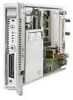
Technology HP BladeSystem bc1500 Blade PC Features The Blade PC is simple to install, deploy, and service. A Blade PC that requires out-of-the-rack upgrades, service, or maintenance can be easily replaced by another Blade PC. The following figure shows a Blade PC. Blade PC A Blade PC supports - HP Bc1500 | Setup and Installation Guide: HP BladeSystem bc1500 Blade PC and PC - Page 16
into the system board and cannot be removed. Memory The Blade PC supports the following memory features: ■ DDR 333 (2 SODIMM connectors) For more information, refer to QuickSpecs located on the HP website: www.hp.com ■ 512MB system memory expandable to 2GB with two 1GB SODIMMs Mass Storage - HP Bc1500 | Setup and Installation Guide: HP BladeSystem bc1500 Blade PC and PC - Page 17
Blade PC ROM features include: ■ 1MB ROM to support system and video ■ Flashbin utility used to upgrade the system ROM ■ Hardware boot block protection ■ Remote ROM flash support ■ Bootable USB diskette drive support ■ Bootable USB CD-ROM drive (limited support) Setup and Installation Guide www.hp - HP Bc1500 | Setup and Installation Guide: HP BladeSystem bc1500 Blade PC and PC - Page 18
a centralized management and monitoring system for the HP PC BL Enclosure and blade PCs. The Integrated Administrator acts as a combination terminal server and remote power controller, enabling out-of-band, secure, serial console connections to all Blade PCs in the enclosure. ■ Computer Setup (F10 - HP Bc1500 | Setup and Installation Guide: HP BladeSystem bc1500 Blade PC and PC - Page 19
ROM Flash Using the Smart Components for Remote ROM Flash with the Remote Deployment Utility (RDU) console application, Remote ROM Flash enables you to upgrade the firmware (BIOS) from a remote location. ■ HP PC Blade Enclosure C-GbE Interconnect Switch Setup and Installation Guide www.hp.com 2-9 - HP Bc1500 | Setup and Installation Guide: HP BladeSystem bc1500 Blade PC and PC - Page 20
and Management." Diagnostic Features The hardware, software, and firmware diagnostic tools that are available include: ■ HP PC Blade Enclosure Integrated Administrator ■ Diagnostic adapter for local Blade PC access (requires optional graphics diagnostic card) ■ Optional graphics diagnostic - HP Bc1500 | Setup and Installation Guide: HP BladeSystem bc1500 Blade PC and PC - Page 21
detailed information on these requirements, refer to the HP PC Blade Enclosure System Overview and Planning white paper at the HP website: www.hp.com Rack Warnings and Cautions Before installing your attached to the rack for single-rack installation. Setup and Installation Guide www.hp.com 3-1 - HP Bc1500 | Setup and Installation Guide: HP BladeSystem bc1500 Blade PC and PC - Page 22
side panels of the rack must be a minimum of 7 cm (2.75 inches). Ä CAUTION: The PC Blade Enclosure is shipped without blanking panels. Always use blanking panels (available as an option) to fill in improper cooling that can lead to thermal damage. 3-2 www.hp.com Setup and Installation Guide - HP Bc1500 | Setup and Installation Guide: HP BladeSystem bc1500 Blade PC and PC - Page 23
Installation HP PC Blade Enclosure Warnings and Cautions Before installing the HP PC Blade Enclosure, carefully review the following warnings and cautions: Å WARNING: To reduce the risk of personal injury or damage to equipment, heed all warnings and cautions throughout the installation instructions - HP Bc1500 | Setup and Installation Guide: HP BladeSystem bc1500 Blade PC and PC - Page 24
the enclosure with the rails while the other two people support the weight of the enclosure. Å WARNING: The HP PC Blade Enclosure has two power cords for redundant AC power sources. If it is necessary to remove power for servicing, disconnect all power by removing both power supply cords from - HP Bc1500 | Setup and Installation Guide: HP BladeSystem bc1500 Blade PC and PC - Page 25
same system as the DHCP server), and the Rapid Deployment CD included with your enclosure. Alternate Deployment Method If you are not using HP Rapid Deployment Pack, use your preferred deployment infrastructure. Blade PCs have a PXE-enabled NIC (the first NIC only) and support bootable USB CD-ROM - HP Bc1500 | Setup and Installation Guide: HP BladeSystem bc1500 Blade PC and PC - Page 26
HP, Compaq branded, and third-party racks Ä CAUTION: Always install either a Blade PC or a Blade PC blank in each Blade PC HP PC Blade Enclosure. Ä CAUTION: Do not ship the blade PCs and enclosure while inside the rack without first installing the HP PC Blade the HP PC Blade Enclosure into an HP, - HP Bc1500 | Setup and Installation Guide: HP BladeSystem bc1500 Blade PC and PC - Page 27
Planning the Installation Blade PCs Standard rack-mounting hardware Item 1 2 Not shown Description Rack rails (2, left markings to identify left and right rack rails (from the front of the rack) Blade PCs ship in packages of one or ten Blade PCs. Setup and Installation Guide www.hp.com 3-7 - HP Bc1500 | Setup and Installation Guide: HP BladeSystem bc1500 Blade PC and PC - Page 28
the PC Blade HP install your HP CCI solution. This method helps ensure top performance from the start and is especially valuable for business-critical environments. Contact your HP account representative to obtain more detailed information and pricing. 3-8 www.hp.com Setup and Installation Guide - HP Bc1500 | Setup and Installation Guide: HP BladeSystem bc1500 Blade PC and PC - Page 29
the HP CCI solution ■ Powering down the HP CCI solution ❏ Powering down a Blade PC ❏ Powering down the enclosure ■ Installing a Blade PC ■ Removing a Blade PC ■ Installing additional memory ■ Attaching the diagnostic adapter and optional graphics diagnostic card Setup and Installation Guide www.hp - HP Bc1500 | Setup and Installation Guide: HP BladeSystem bc1500 Blade PC and PC - Page 30
and work your way up with additional enclosures as needed. IMPORTANT: Match the hole pattern on the rack template with the holes in the rack supports. Measuring with the rack template 4-2 www.hp.com Setup and Installation Guide - HP Bc1500 | Setup and Installation Guide: HP BladeSystem bc1500 Blade PC and PC - Page 31
Installing and Cabling the HP CCI Solution 3. Align the rack template so that its sides are square with the sides of the rack. IMPORTANT: Tick marks on the rack supports help you to maintain proper alignment of ✎ Store the rack template for future use. Setup and Installation Guide www.hp.com 4-3 - HP Bc1500 | Setup and Installation Guide: HP BladeSystem bc1500 Blade PC and PC - Page 32
2. 4. Adjust the rack rail to the depth of the rack using the numbers on the rack rail as a guide 3. The depth of a Compaq branded rack (29 inches) is clearly indicated on the rack rails. Unlocking and may need to be tightened to ensure proper fit. 4-4 www.hp.com Setup and Installation Guide - HP Bc1500 | Setup and Installation Guide: HP BladeSystem bc1500 Blade PC and PC - Page 33
Installing and Cabling the HP CCI Solution 5. Insert the rear of the right rack rail into the rack at the marks you made when measuring with the template the left and right rack rails (from the front of the rack). Inserting the rear of the rack rail Setup and Installation Guide www.hp.com 4-5 - HP Bc1500 | Setup and Installation Guide: HP BladeSystem bc1500 Blade PC and PC - Page 34
Installing and Cabling the HP CCI Solution 6. Compress the spring-loaded rack rail toward the rear of the rack 1. 7. Using the marks you made equipment. Once the right rack rail is properly installed, install the left rack rail using the same procedure. 4-6 www.hp.com Setup and Installation Guide - HP Bc1500 | Setup and Installation Guide: HP BladeSystem bc1500 Blade PC and PC - Page 35
thumbscrews with white hexagonal washers, which are compatible with Compaq-branded racks and some HP and third-party racks ■ Size M6 thumbscrews with black hexagonal washers, which are and hexagonal washer 3. Removing a thumbscrew and hexagonal washer Setup and Installation Guide www.hp.com 4-7 - HP Bc1500 | Setup and Installation Guide: HP BladeSystem bc1500 Blade PC and PC - Page 36
Installing and Cabling the HP CCI Solution 4. Place the hexagonal washer at the back of the hole in level, a third person must assist with aligning the enclosure with the rails while the other two people support the weight of the enclosure. Ä CAUTION: Do not remove the enclosure from the rack by the - HP Bc1500 | Setup and Installation Guide: HP BladeSystem bc1500 Blade PC and PC - Page 37
the interconnect switch installed in your solution. The procedure for cabling an enclosure consists of the following steps: ■ Identifying the interconnect switch connectors ■ Cabling the blade enclosure Setup and Installation Guide www.hp.com 4-9 - HP Bc1500 | Setup and Installation Guide: HP BladeSystem bc1500 Blade PC and PC - Page 38
HP CCI Solution HP PC Blade Enclosure C-GbE Interconnect Switch Connectors The interconnect switch reduces forty 10/100 Ethernet networking connections coming from the Blade PCs port 42 6 Integrated Administrator console connector (serial) 7 Gigabit Ethernet hp.com Setup and Installation Guide - HP Bc1500 | Setup and Installation Guide: HP BladeSystem bc1500 Blade PC and PC - Page 39
console connector (serial)* Integrated Administrator module 5 RJ-45 connector for Blade PC bay 1 NIC B RJ-45 patch panel 6 RJ-45 connector for Blade PC bay 1 NIC A RJ-45 patch panel ✎ *These items denote connectors for the Integrated Administrator module. Setup and Installation Guide www.hp - HP Bc1500 | Setup and Installation Guide: HP BladeSystem bc1500 Blade PC and PC - Page 40
(RJ-45) connectors unless the device is listed as a supported device on the Quickspecs. Connecting an unsupported external device to the enclosure link (RJ-45) connectors may damage your external device. To cable a HP PC Blade Enclosure already installed in a rack: 1. For accessing and configuring - HP Bc1500 | Setup and Installation Guide: HP BladeSystem bc1500 Blade PC and PC - Page 41
Installing and Cabling the HP CCI Solution 4. Bundle network and power cables together and route them to the outer edge of the rack. Cabling the solution with the interconnect switch Cabling the solution with the RJ-45 patch panel Setup and Installation Guide www.hp.com 4-13 - HP Bc1500 | Setup and Installation Guide: HP BladeSystem bc1500 Blade PC and PC - Page 42
4 for each Blade PC enclosure you have installed. Null-Modem Cable If you are cabling a serial device such as a laptop computer to the console connector on the 5 DSR 6 4 CD 1 4 DTR 4 1 & 6 TxD 3 2 DB-25 PIN 3 2 5 4 7 20 20 6 & 8 3 4-14 www.hp.com Setup and Installation Guide - HP Bc1500 | Setup and Installation Guide: HP BladeSystem bc1500 Blade PC and PC - Page 43
Install or upgrade memory before installing Blade PCs into an enclosure. See the "Installing Additional Memory" section in this chapter. Ä CAUTION: The HP PC Blade Enclosure is shipped without Blade PC blanks. Always populate the Blade PC bays with either a Blade PC or a Blade PC blank (available as - HP Bc1500 | Setup and Installation Guide: HP BladeSystem bc1500 Blade PC and PC - Page 44
installed, remove the Blade PC blank: a. Press the ejector tabs on the Blade PC blank 1. b. Slide the Blade PC blank out of the bay 2. Removing a single-bay Blade PC blank Removing a five-bay Blade PC blank ✎ Store the Blade PC blank for future use. 4-16 www.hp.com Setup and Installation Guide - HP Bc1500 | Setup and Installation Guide: HP BladeSystem bc1500 Blade PC and PC - Page 45
." 4. Install the Blade PC: a. Align the Blade PC with the Blade PC bay on the enclosure and slide the blade partially into the enclosure. b. Press the release latch 1 on the blade. c. Pull down the ejector lever 2. Opening the blade eject lever Setup and Installation Guide www.hp.com 4-17 - HP Bc1500 | Setup and Installation Guide: HP BladeSystem bc1500 Blade PC and PC - Page 46
ejector lever until you hear an audible click that indicates the Blade PC is properly seated 2. Installing a Blade PC IMPORTANT: Install a Blade PC for each of the blanks you have removed. 5. Repeat steps 2 to 4 for each Blade PC you wish to install. 4-18 www.hp.com Setup and Installation Guide - HP Bc1500 | Setup and Installation Guide: HP BladeSystem bc1500 Blade PC and PC - Page 47
the Blade PC is not active. For specific information about Blade PC LEDs, see Appendix E, "LEDs and Switches." 2. If the Blade PC is active, notify users and stop applications as necessary. 3. Shut down the operating system. This may shut off the Blade PC power. Setup and Installation Guide www.hp - HP Bc1500 | Setup and Installation Guide: HP BladeSystem bc1500 Blade PC and PC - Page 48
on the front of the Blade PC IMPORTANT: Refer to the HP PC Blade Enclosure Integrated Administrator User Guide to power down the Blade PC using the Integrated Administrator. Powering down the Blade PC To perform an emergency shut down of a Blade PC, press and hold the blade power button for four - HP Bc1500 | Setup and Installation Guide: HP BladeSystem bc1500 Blade PC and PC - Page 49
on the enclosure may result in the loss of any unsaved data on all Blade PCs. Removing a Blade PC To remove a Blade PC: 1. Press the release latch 1. 2. Pull down the ejector lever 2. 3. Remove the Blade PC from the enclosure 3. Removing a Blade PC Setup and Installation Guide www.hp.com 4-21 - HP Bc1500 | Setup and Installation Guide: HP BladeSystem bc1500 Blade PC and PC - Page 50
Memory The Blade PCs support the following memory features: ■ Unregistered SODIMM DDR 333 memory For more information, refer to QuickSpecs located on the HP website: www.hp.com ■ 512MB system memory expandable to 2GB ■ Two SODIMM slots To install SODIMMs on a Blade PC: 1. Power down the Blade PC - HP Bc1500 | Setup and Installation Guide: HP BladeSystem bc1500 Blade PC and PC - Page 51
and Cabling the HP CCI Solution IMPORTANT: Step 5 applies only when you wish to upgrade SODIMMs. 5. Remove the existing SODIMM: a. Release the latches on each side of the SODIMM slot 1 1. b. Remove the SODIMM from the Blade PC 2. Removing an SODIMM Setup and Installation Guide www.hp.com 4-23 - HP Bc1500 | Setup and Installation Guide: HP BladeSystem bc1500 Blade PC and PC - Page 52
Installing and Cabling the HP CCI Solution 6. Install SODIMM 1: a. Match the notch on the SODIMM with the tab on the SODIMM socket and insert latches snap into place 2. Installing an SODIMM 7. Repeat step 6 to install a second SODIMM into SODIMM slot 2. 4-24 www.hp.com Setup and Installation Guide - HP Bc1500 | Setup and Installation Guide: HP BladeSystem bc1500 Blade PC and PC - Page 53
chapter. 2. Remove the Blade PC. See the "Removing a Blade PC" section in this chapter. 3. Lay the Blade PC down on a flat surface and install the optional graphics diagnostic card into the sockets. Installing the optional graphics diagnostic card Setup and Installation Guide www.hp.com 4-25 - HP Bc1500 | Setup and Installation Guide: HP BladeSystem bc1500 Blade PC and PC - Page 54
in this chapter. 5. Insert the diagnostic adapter into the diagnostic connector on the Blade PC 1. 6. Tighten the thumbscrews securing the diagnostic adapter in place 2. Attaching the USB 2.0 diagnostic adapter Attaching the USB 1.1 diagnostic adapter 4-26 www.hp.com Setup and Installation Guide - HP Bc1500 | Setup and Installation Guide: HP BladeSystem bc1500 Blade PC and PC - Page 55
Installing and Cabling the HP CCI Solution Use the following figure and table to identify connectors on the USB 2.0 diagnostic adapter. 6 Description PS/2 Mouse connector PS/2 Keyboard connector Serial connector Video connector USB 2.0 #1 USB 2.0 #2 Setup and Installation Guide www.hp.com 4-27 - HP Bc1500 | Setup and Installation Guide: HP BladeSystem bc1500 Blade PC and PC - Page 56
Installing and Cabling the HP CCI Solution Use the following figure and table to identify connectors on the USB 1.1 diagnostic adapter. 5 6 Description PS/2 Mouse connector USB 1.1 #2 Serial connector PS/2 Keyboard connector USB 1.1 #1 Video connector 4-28 www.hp.com Setup and Installation Guide - HP Bc1500 | Setup and Installation Guide: HP BladeSystem bc1500 Blade PC and PC - Page 57
❏ Supported operating systems ❏ Computer Setup (F10) Utility ❏ Flashbin Utility ❏ Remote ROM Flash ❏ HP PC Blade Enclosure Integrated Administrator ❏ HP Systems Insight Manager ❏ HP PC Blade Enclosure C-GbE Interconnect Switch management tools and utilities Setup and Installation Guide www.hp.com - HP Bc1500 | Setup and Installation Guide: HP BladeSystem bc1500 Blade PC and PC - Page 58
console to automatically install pre-defined configurations on newly installed Blade PCs. For more information about HP www.hp.com/servers/rdp Alternate Deployment Methods Blade PCs have a PXE-enabled NIC (the first NIC only) and support Blade PCs. 5-2 www.hp.com Setup and Installation Guide - HP Bc1500 | Setup and Installation Guide: HP BladeSystem bc1500 Blade PC and PC - Page 59
■ Flash the Blade PC ROM (See the "Flashing the Blade PC ROM" section in this chapter.) ■ View software information during deployment For instructions on how to attach the diagnostic adapter and optional graphics diagnostic card, see Chapter 4, "Installing and Cabling the HP CCI Solution." IMPORTANT - HP Bc1500 | Setup and Installation Guide: HP BladeSystem bc1500 Blade PC and PC - Page 60
the Integrated Administrator and press the Esc key then press the 0 (zero) key. Refer to the HP PC Blade Enclosure Integrated Administrator User Guide for details. ✎ The function keys in remote console are accessed by pressing Esc then the numbers 1 through 0 for F1 through F10. F11 is accessed - HP Bc1500 | Setup and Installation Guide: HP BladeSystem bc1500 Blade PC and PC - Page 61
processors have this listed twice) • HyperTransport™ Speed • Memory Size • Integrated MAC (address for embedded, enabled BIOS (includes family name and version) • Blade Serial Number • Asset Tracking Number • Rack system time and date. ✎ Support for specific Computer Setup options may - HP Bc1500 | Setup and Installation Guide: HP BladeSystem bc1500 Blade PC and PC - Page 62
and Exit Applies the currently selected default settings and clears any established passwords. Ignore Changes and Exit Exits Computer Setup without applying or saving any 3.5" 1.44 MB and 5.25" 1.2 MB. ✎ Support for specific Computer Setup options may vary depending on the hardware configuration. - HP Bc1500 | Setup and Installation Guide: HP BladeSystem bc1500 Blade PC and PC - Page 63
(IDE devices only) Specifies the active data transfer mode. Options (subject to device capabilities) are PIO 0, Max PIO, Enhanced DMA, Ultra DMA 0, and Max UDMA. ✎ Support for specific Computer Setup options may vary depending on the hardware configuration. Setup and Installation - HP Bc1500 | Setup and Installation Guide: HP BladeSystem bc1500 Blade PC and PC - Page 64
number of sectors per track may not exceed 63. These fields are only visible and changeable when the drive translation mode is set to User. ✎ Support for specific Computer Setup options may vary depending on the hardware configuration. 5-8 www - HP Bc1500 | Setup and Installation Guide: HP BladeSystem bc1500 Blade PC and PC - Page 65
manually. BIOS IDE DMA Transfers (enable/disable) Allows you to control how BIOS disk I/O requests are serviced. When "Enable" is selected, the BIOS will service is selected, the BIOS will service ATA disk read and write system. ✎ Support for specific Computer Setup options may vary - HP Bc1500 | Setup and Installation Guide: HP BladeSystem bc1500 Blade PC and PC - Page 66
arrow keys to select the preferred bootable device and press Enter. The computer then boots from the selected non-default device for this one time. ✎ Support for specific Computer Setup options may vary depending on the hardware configuration. 5-10 www - HP Bc1500 | Setup and Installation Guide: HP BladeSystem bc1500 Blade PC and PC - Page 67
ports Network Service Boot Enables/disables the computer's ability to boot from an operating system installed on a network server. System IDs ID entry. ✎ Support for specific Computer Setup options may vary depending on the hardware configuration. Setup and Installation Guide www.hp.com 5-11 - HP Bc1500 | Setup and Installation Guide: HP BladeSystem bc1500 Blade PC and PC - Page 68
enable/disable). Enabling this feature will display the text "F12 = Network Service Boot" during POST. Disabling this feature prevents the text from being ✎ Support for specific Computer Setup options may vary depending on the hardware configuration. 5-12 www.hp.com Setup and Installation Guide - HP Bc1500 | Setup and Installation Guide: HP BladeSystem bc1500 Blade PC and PC - Page 69
is that a popular memory manager, HIMEM.SYS, does not work properly when USB buffers are at top of memory AND the system has 64 MB or less of RAM. ✎ Support for specific Computer Setup options may vary depending on the hardware configuration. Setup and Installation Guide www.hp.com 5-13 - HP Bc1500 | Setup and Installation Guide: HP BladeSystem bc1500 Blade PC and PC - Page 70
from being used by the operating system and reduces the power used by the computer in S5. • Processor Cache (enable/disable). • Spread Spectrum (enable/disable) ✎ Support for specific Computer Setup options may vary depending on the hardware configuration. 5-14 www - HP Bc1500 | Setup and Installation Guide: HP BladeSystem bc1500 Blade PC and PC - Page 71
to a PXE server. This is typically used to download a corporate image to a hard drive. The NIC option ROM takes up memory space below 1MB commonly • USB 2.0 Capability (automatic, enable/disable) ✎ Support for specific Computer Setup options may vary depending on Installation Guide www.hp.com 5-15 - HP Bc1500 | Setup and Installation Guide: HP BladeSystem bc1500 Blade PC and PC - Page 72
in Chapter 4. 3. Remove the Blade PC. See the "Removing a Blade PC" section in Chapter 4. 4. Install the optional graphics diagnostic card on the Blade PC. 5. Install the Blade PC in the enclosure. 6. Attach the diagnostic adapter to the Blade PC. 5-16 www.hp.com Setup and Installation Guide - HP Bc1500 | Setup and Installation Guide: HP BladeSystem bc1500 Blade PC and PC - Page 73
is a centralized management and monitoring system for the HP PC Blade Enclosure and blade PCs. The Integrated Administrator acts as a combination terminal server and remote power controller, enabling out-of-band, secure, serial console connections to all Blade PCs in the enclosure, and offers all of - HP Bc1500 | Setup and Installation Guide: HP BladeSystem bc1500 Blade PC and PC - Page 74
Blade PC's serial console ❏ Enables full control over Blade PC blade status. ■ Offline console buffering (when not connected) and event logging ❏ Operating system console logging ❏ Blade PC Administrator's RS-232 console ❏ Secure Sockets its own processor, memory, NIC, and flash firmware update with code - HP Bc1500 | Setup and Installation Guide: HP BladeSystem bc1500 Blade PC and PC - Page 75
associated with the optional interconnect switch, refer to the HP PC Blade Enclosure C-GbE Interconnect Switch User Guide. ■ Blade PC management ❏ Virtual power and unit identification (UID) buttons ❏ Remote serial console ❏ General health status ■ User management ❏ Add/remove/modify administrators - HP Bc1500 | Setup and Installation Guide: HP BladeSystem bc1500 Blade PC and PC - Page 76
Deployment and Management For more information, including instructions on flashing the Integrated Administrator ROM, refer to the HP PC Blade Enclosure Integrated Administrator User Guide on the Documentation CD that ships with your enclosure. Blade PC Event Messages The event list displays the - HP Bc1500 | Setup and Installation Guide: HP BladeSystem bc1500 Blade PC and PC - Page 77
HP server platforms (including hundreds of Blade PCs) from a single console. You can use HP Systems Insight Manager to view each Blade PC and the Integrated Administrator of each blade instructions in the following section to view and print the event list from within HP HP list of Blade PCs or - HP Bc1500 | Setup and Installation Guide: HP BladeSystem bc1500 Blade PC and PC - Page 78
When the new page opens, click on the browser File/Print. HP PC Blade Enclosure C-GbE Interconnect Switch Management Tools and Utilities The interconnect switch offers via the Integrated Administrator console connector or remotely via Telnet ■ SNMP agent support for interconnect switch management, - HP Bc1500 | Setup and Installation Guide: HP BladeSystem bc1500 Blade PC and PC - Page 79
LEDs on each Gigabit Ethernet uplink connector ■ Two-level (level 1, level 15) username and password for all management interfaces ❏ Ability to recover from lost management-level password ❏ Configurable time-out period on Telnet and console sessions Setup and Installation Guide www.hp.com 5-23 - HP Bc1500 | Setup and Installation Guide: HP BladeSystem bc1500 Blade PC and PC - Page 80
- HP Bc1500 | Setup and Installation Guide: HP BladeSystem bc1500 Blade PC and PC - Page 81
classes to bear a label indicating the interference potential of the device as well as additional operating instructions for the user. The rating label on the device shows the classification (A or B) of corresponding statement in the following sections. Setup and Installation Guide www.hp.com A-1 - HP Bc1500 | Setup and Installation Guide: HP BladeSystem bc1500 Blade PC and PC - Page 82
radiate radio frequency energy and, if not installed and used in accordance with the instructions, may cause harmful interference to radio communications. Operation of this equipment in a dealer or an experienced radio or television technician for help A-2 www.hp.com Setup and Installation Guide - HP Bc1500 | Setup and Installation Guide: HP BladeSystem bc1500 Blade PC and PC - Page 83
■ Hewlett-Packard Company P. O. Box 692000, Mail Stop 530113 Houston, Texas 77269-2000 ■ 1-800-HP-INVENT (1-800-474-6836) (For continuous quality improvement, calls may be recorded or monitored.) For questions compliance with FCC Rules and Regulations. Setup and Installation Guide www.hp.com A-3 - HP Bc1500 | Setup and Installation Guide: HP BladeSystem bc1500 Blade PC and PC - Page 84
Notice This product complies with the following EU directives: ■ Low Voltage Directive 73/23/EEC ■ EMC Directive 89/336/EEC Compliance with the directives implies conformity to applicable number (used only if applicable - refer to the product label) A-4 www.hp.com Setup and Installation Guide - HP Bc1500 | Setup and Installation Guide: HP BladeSystem bc1500 Blade PC and PC - Page 85
Japanese Notice Regulatory Compliance Notices Korean Notice Class A Equipment Class B Equipment Setup and Installation Guide www.hp.com A-5 - HP Bc1500 | Setup and Installation Guide: HP BladeSystem bc1500 Blade PC and PC - Page 86
other than those specified herein or in the laser product's installation guide may result in hazardous radiation exposure. To reduce the risk of exposure Do not try to open the module enclosure. There are no user-serviceable components inside. • Do not operate controls, make adjustments, or perform - HP Bc1500 | Setup and Installation Guide: HP BladeSystem bc1500 Blade PC and PC - Page 87
incorrectly replaced or mistreated. Replacement is to be done by an authorized service provider using the spare designated for this product. For more information about collection system or return them to HP, your authorized HP partners, or their agents. Setup and Installation Guide www.hp.com A-7 - HP Bc1500 | Setup and Installation Guide: HP BladeSystem bc1500 Blade PC and PC - Page 88
- HP Bc1500 | Setup and Installation Guide: HP BladeSystem bc1500 Blade PC and PC - Page 89
removing them from their containers. ■ Avoid touching pins, leads, or circuitry. ■ Always be properly grounded when touching a static-sensitive component or assembly. Setup and Installation Guide www.hp.com B-1 - HP Bc1500 | Setup and Installation Guide: HP BladeSystem bc1500 Blade PC and PC - Page 90
, or boot straps at standing workstations. Wear the straps on both feet when standing on conductive floors or dissipating floor mats. ■ Use conductive field service tools. ■ Use a portable field service kit with a folding static-dissipating work mat. B-2 www.hp.com Setup and Installation Guide - HP Bc1500 | Setup and Installation Guide: HP BladeSystem bc1500 Blade PC and PC - Page 91
in troubleshooting and performing basic diagnostic functions. The following table lists the numeric codes and text messages specific to Blade PCs. Failure 162-System Options Not Set Red Amber Blade system board has failed. CMOS was cleared or the blade's battery has failed. 163-Time & Date Not - HP Bc1500 | Setup and Installation Guide: HP BladeSystem bc1500 Blade PC and PC - Page 92
with the blade turned off. 2. Use a different keyboard that is known to work properly. 3. Replace the blade. 1. Run Drive Protection System if applicable. 2. Apply firmware patch (www.hp.com/support). 3. Back up contents and replace the hard drive. C-2 www.hp.com Setup and Installation Guide - HP Bc1500 | Setup and Installation Guide: HP BladeSystem bc1500 Blade PC and PC - Page 93
has adequate ventilation. 2. Check the processor heat sink. 3. Replace the blade. Run Computer Setup to update the MBR backup. 1. Run Computer Setup from www.hp.com. 2. Run Computer Setup, enter serial number under Security, System ID, then save changes. Setup and Installation Guide www.hp.com C-3 - HP Bc1500 | Setup and Installation Guide: HP BladeSystem bc1500 Blade PC and PC - Page 94
- HP Bc1500 | Setup and Installation Guide: HP BladeSystem bc1500 Blade PC and PC - Page 95
enclosure does not start after you have performed initial troubleshooting procedures, use the tables in this section to identify possible reasons for the problem and possible solutions. ■ When the Blade PC does not start You are provided with initial instructions on what to try and where to go for - HP Bc1500 | Setup and Installation Guide: HP BladeSystem bc1500 Blade PC and PC - Page 96
troubleshooting Some troubleshooting can be performed remotely. You are provided with instructions for opening a remote console session, accessing the Blade PC Computer Setup (F10) Utility, reviewing Blade PC activity, and powering off a Blade PC. D-2 www.hp.com Setup and Installation Guide - HP Bc1500 | Setup and Installation Guide: HP BladeSystem bc1500 Blade PC and PC - Page 97
Troubleshooting When the Enclosure Does Not Start This section provides systematic instructions on what to try and where to go for help for the most common problems encountered during initial startup of the HP PC Blade Enclosure. If you are having specific Blade PC trouble, see the "When the Blade - HP Bc1500 | Setup and Installation Guide: HP BladeSystem bc1500 Blade PC and PC - Page 98
enclosure and all Blade PCs. IMPORTANT: If the enclosure does not restart, proceed to "Table D-1: Enclosure Diagnostic Steps" in this appendix. 10. Be sure that connectors and components are seated properly. Refer to the "General Loose Connections" section in the Servers Troubleshooting Guide on the - HP Bc1500 | Setup and Installation Guide: HP BladeSystem bc1500 Blade PC and PC - Page 99
Troubleshooting for the problem, options console, contact HP or your authorized service provider for parts and service. If no, see Table D-8. Ä CAUTION: Pressing the enclosure power button while the enclosure is running shuts down the enclosure and all Blade PCs. Setup and Installation Guide www.hp - HP Bc1500 | Setup and Installation Guide: HP BladeSystem bc1500 Blade PC and PC - Page 100
Troubleshooting Table D-2: Is the Power LED the enclosure power button while the enclosure is running shuts down the enclosure and all Blade PCs. Be sure that the pins on the power supplies are not damaged. Be sure solid green, return to Table D-1. D-6 www.hp.com Setup and Installation Guide - HP Bc1500 | Setup and Installation Guide: HP BladeSystem bc1500 Blade PC and PC - Page 101
Troubleshooting Table D-3: Is supply fan blades from spinning. At least one power supply fan has failed. Contact HP or your authorized service provider for parts and service. No, Contact HP or your authorized service provider for parts and service. Setup and Installation Guide www.hp.com D-7 - HP Bc1500 | Setup and Installation Guide: HP BladeSystem bc1500 Blade PC and PC - Page 102
Troubleshooting blades from spinning. At least one power supply fan has failed. You no longer have adequate cooling. Contact HP or your authorized service provider for parts and service over-current condition. Contact HP or your authorized service provider for parts and service. Yes. If the fault - HP Bc1500 | Setup and Installation Guide: HP BladeSystem bc1500 Blade PC and PC - Page 103
Troubleshooting Ä CAUTION: Pressing the enclosure power button while the enclosure is running shuts down the enclosure and all Blade PCs failed. Contact HP or your authorized service provider for parts and service. The connector and all Blade PCs. Yes, it is green. If the enclosure - HP Bc1500 | Setup and Installation Guide: HP BladeSystem bc1500 Blade PC and PC - Page 104
service. Yes, it is green. The Integrated Administrator has not detected any degraded or failed components. Check your local or remote console for error messages. Go toTable D-6. Contact HP or your authorized service provider for parts and service. D-10 www.hp.com Setup and Installation Guide - HP Bc1500 | Setup and Installation Guide: HP BladeSystem bc1500 Blade PC and PC - Page 105
may not be connected properly. console cable is securely connected. The Integrated Administrator module has failed. Go to table D-7. The Integrated Administrator firmware may be damaged. If these steps do not solve the problem, contact HP or your authorized service provider for assistance. Yes - HP Bc1500 | Setup and Installation Guide: HP BladeSystem bc1500 Blade PC and PC - Page 106
Solution." Be sure that the Integrated Administrator console connector or the Integrated Administrator management connector is securely seated. Refer to the HP PC Blade Enclosure Integrated Administrator User Guide for further troubleshooting information. D-12 www.hp.com Setup and Installation - HP Bc1500 | Setup and Installation Guide: HP BladeSystem bc1500 Blade PC and PC - Page 107
service. Contact HP or your authorized service provider for parts and service. Check your local or remote console for error messages. Go to table D-6. If these steps have not identified the problem, contact HP or your authorized service provider for assistance. Setup and Installation Guide www.hp - HP Bc1500 | Setup and Installation Guide: HP BladeSystem bc1500 Blade PC and PC - Page 108
Troubleshooting When the Blade PC Does Not Start This section provides systematic instructions on what to try and where to go for help for the most common problems encountered during initial Power On Self-Test (POST) of a Blade PC. The Blade PC must first complete this test each time you power up, - HP Bc1500 | Setup and Installation Guide: HP BladeSystem bc1500 Blade PC and PC - Page 109
the optional graphics diagnostic card on the Blade PC before using a monitor with the diagnostic adapter. If the Blade PC completes POST and attempts to load the operating system, go to the "Problems After Initial Boot" section in this appendix. Setup and Installation Guide www.hp.com D-15 - HP Bc1500 | Setup and Installation Guide: HP BladeSystem bc1500 Blade PC and PC - Page 110
Troubleshooting Blade PC Diagnostic Steps If your Blade PC problem, options available to assist in diagnosis, and possible solutions. Table D-9: Blade PC Diagnostic Steps Question Action Question 1: Is the power LED on the Blade PC when connected to the Blade PC through the diagnostic adapter? - HP Bc1500 | Setup and Installation Guide: HP BladeSystem bc1500 Blade PC and PC - Page 111
PC comes on and turns green, the problem lies with the original bay. • If the power LED on the Blade PC does not come on, try placing a different Blade PC in the original bay. If the power LED on the new Blade PC comes on, the old Blade PC may have failed. • Contact HP or your authorized service - HP Bc1500 | Setup and Installation Guide: HP BladeSystem bc1500 Blade PC and PC - Page 112
Troubleshooting Table D-11: Is the Health LED on the Blade PC Green? Answer Possible Reasons Possible Solutions No, it is off. The Blade PC is off. Press the power button on the Blade PC. The enclosure power supplies have failed or the blade's system board power circuitry has failed. Check - HP Bc1500 | Setup and Installation Guide: HP BladeSystem bc1500 Blade PC and PC - Page 113
power supply has failed. Move the blade to a different bay to see if the blade functions properly. If this corrects the problem, there is a problem with the enclosure backplane. Contact HP or your authorized service provider for replacement parts and service. System board (hot swap circuitry) has - HP Bc1500 | Setup and Installation Guide: HP BladeSystem bc1500 Blade PC and PC - Page 114
Troubleshooting Table D12: Is the NIC A or NIC B LED on the Blade PC Illuminated? Answer Possible Reasons Possible Appendix E, "LEDs and Switches" for instructions on clearing CMOS. The system ROM may be corrupted. Contact HP or your authorized service provider for assistance. Yes Video is - HP Bc1500 | Setup and Installation Guide: HP BladeSystem bc1500 Blade PC and PC - Page 115
Troubleshooting Problems After Initial Boot Once your Blade PC has passed POST, you may still encounter errors, such as an inability to load your operating system. Use Table D-14 to troubleshoot Blade PC installation problems that occur after the initial boot. Table D-14: Problems After Initial - HP Bc1500 | Setup and Installation Guide: HP BladeSystem bc1500 Blade PC and PC - Page 116
you to connect to the server blade terminal interface. Command Line Interface To access the remote console using the command line interface, type: CONNECT BAY IMPORTANT: A Blade PC can only support one remote console session at a time. D-22 www.hp.com Setup and Installation Guide - HP Bc1500 | Setup and Installation Guide: HP BladeSystem bc1500 Blade PC and PC - Page 117
Troubleshooting Accessing the Computer Setup (F10) Utility for a Blade PC IMPORTANT: Enclosure administrators and group administrators with access to the bay can select the Remote Console button to open a remote text-based console to the server blade in the bay. Web-Based Interface To access the - HP Bc1500 | Setup and Installation Guide: HP BladeSystem bc1500 Blade PC and PC - Page 118
console session: a. Press Ctrl_ (control underscore). b. Press D. Command Line Interface To access the Computer Setup (F10) Utility of a Blade PC using the command line interface: 1. If the Blade PC is running the operating system, reboot the Blade PC . D-24 www.hp.com Setup and Installation Guide - HP Bc1500 | Setup and Installation Guide: HP BladeSystem bc1500 Blade PC and PC - Page 119
Troubleshooting 5. To close the remote console session: a. Press Ctrl_ (control underscore). b. Press D. Reviewing Activity of a Blade PC IMPORTANT: This task can only be performed for a given Blade PC to display. The system log of the Blade PC is not stored between reboots, so the information - HP Bc1500 | Setup and Installation Guide: HP BladeSystem bc1500 Blade PC and PC - Page 120
Troubleshooting Powering Off the Blade PC Ä CAUTION: Rebooting or powering off the Blade PC removes all power from the server blade and ends all open sessions. Web-Based Interface To reboot or power off the Blade PC using the Web-based user interface: 1. Click the Bays tab. 2. Click Bay List in the - HP Bc1500 | Setup and Installation Guide: HP BladeSystem bc1500 Blade PC and PC - Page 121
LEDs ■ Blade PC and diagnostic adapter LEDs Enclosure Front Panel LEDs Use the following figure and table to determine the location and function of the enclosure status LEDs on the front panel of the HP PC Blade Enclosure. Enclosure front panel LEDs Setup and Installation Guide www.hp.com E-1 - HP Bc1500 | Setup and Installation Guide: HP BladeSystem bc1500 Blade PC and PC - Page 122
of the enclosure status LEDs on the rear panel of the HP PC Blade Enclosure. Enclosure rear panel LEDs provide the following information: ■ Administrator status Enclosure Rear Panel LEDs with Interconnect Switch HP PC Blade Enclosure C-GbE Interconnect Switch LEDs provide the following information - HP Bc1500 | Setup and Installation Guide: HP BladeSystem bc1500 Blade PC and PC - Page 123
-temperature Blinking amber = Current limit 3 Enclosure power Off = Amber = No power to enclosure Enclosure shutdown; power available; hibernate Green = Enclosure power on Setup and Installation Guide www.hp.com E-3 - HP Bc1500 | Setup and Installation Guide: HP BladeSystem bc1500 Blade PC and PC - Page 124
= Base unit Yellow = Slave unit Off = No stacking 9 Link/activity Green = Network link Flashing green = Network activity Yellow = Port disabled Off = No network link E-4 www.hp.com Setup and Installation Guide - HP Bc1500 | Setup and Installation Guide: HP BladeSystem bc1500 Blade PC and PC - Page 125
Off = 10 Enclosure Rear Panel LEDs with optional RJ-45 Patch Panel RJ-45 patch panel LEDs provide status information for each NIC of every Blade PC installed in the enclosure. Use the following figure and table to determine the location and function of the LED on the rear panel when the - HP Bc1500 | Setup and Installation Guide: HP BladeSystem bc1500 Blade PC and PC - Page 126
subsystem critical 5 Enclosure UID Off = Off Blue = Identification of unit 6 RJ-45 link activity On = Off = Network link No network link Flashing = Network activity E-6 www.hp.com Setup and Installation Guide - HP Bc1500 | Setup and Installation Guide: HP BladeSystem bc1500 Blade PC and PC - Page 127
Description 7 Integrated Off = Administrator health Green = Enclosure off, Integrated Administrator health good Enclosure on, Integrated Administrator health good Amber = Integrated Administrator critical Setup and Installation Guide www.hp.com E-7 - HP Bc1500 | Setup and Installation Guide: HP BladeSystem bc1500 Blade PC and PC - Page 128
health LEDs. Hot-plug fan health LEDs Table E-4. Hot-Plug Fan Health LEDs Item LED Status 1 Fan 1 2 Fan 2 3 Fan 3 Green = Normal Amber = Failed 4 Fan 4 E-8 www.hp.com Setup and Installation Guide - HP Bc1500 | Setup and Installation Guide: HP BladeSystem bc1500 Blade PC and PC - Page 129
PC and USB 1.1 diagnostic adapter LEDs have the same orientation and function. Use the following figures and table to determine the location and function of the LEDs. ✎ The USB 2.0 diagnostic adapter has no LEDs. Blade PC LEDs USB 1.1 Diagnostic adapter LEDs Setup and Installation Guide www.hp - HP Bc1500 | Setup and Installation Guide: HP BladeSystem bc1500 Blade PC and PC - Page 130
green = Linked and activity on the network 5 Drive activity Off = No drive activity Blinking green = Drive activity 6 Power Off = No AC power to enclosure or Blade PC Amber = Enclosure on and health good Green = Blade PC power turned on E-10 www.hp.com Setup and Installation Guide - HP Bc1500 | Setup and Installation Guide: HP BladeSystem bc1500 Blade PC and PC - Page 131
the UID LED for easy Blade PC identification 2 Enclosure UID button Activates the UID LED for easy enclosure identification 3 Blade PC power Powers up or down a Blade PC; hold down button for four seconds to perform an emergency shutdown Setup and Installation Guide www.hp.com E-11 - HP Bc1500 | Setup and Installation Guide: HP BladeSystem bc1500 Blade PC and PC - Page 132
Off Function 1 Enclosure UID button Activates the UID LED for easy enclosure identification 2 Enclosure power Powers the enclosure and all Blade PCs up button or down 3 Integrated Administrator reset button Restarts the Integrated Administrator ✎ The enclosure power and UID buttons are - HP Bc1500 | Setup and Installation Guide: HP BladeSystem bc1500 Blade PC and PC - Page 133
F Specifications This appendix provides operating and performance specifications for the following HP CCI solution components: ■ Blade enclosure ■ Blade PC ■ Hot-plug power supply Setup and Installation Guide www.hp.com F-1 - HP Bc1500 | Setup and Installation Guide: HP BladeSystem bc1500 Blade PC and PC - Page 134
cm 27 in Width 48.26 cm 19 in Weight with interconnect tray No Blade PCs 26.76 kg 59 lb 20 Blade PCs 46.7 kg 103 lb Input requirements Rated input voltage 100 to 127 VAC 200 temperature of 45°C. Minimum pressure for storage is 70 KPa. F-2 www.hp.com Setup and Installation Guide - HP Bc1500 | Setup and Installation Guide: HP BladeSystem bc1500 Blade PC and PC - Page 135
Blade PC Specifications Blade PC Operating and Performance Specifications Dimensions Height 11.94 cm 4.7 in Depth 39.37 cm 15.5 in Width 2.03 cm 0.8 in 95% is based on a maximum temperature of 45°C. Minimum pressure for storage is 70 KPa. Setup and Installation Guide www.hp.com F-3 - HP Bc1500 | Setup and Installation Guide: HP BladeSystem bc1500 Blade PC and PC - Page 136
.1 V - 0.5 A ~ 38 A 5 Vaux - 0.2 A ~ 8 A Maximum peak power 700 W Ambient temperature range Operating 10° to 35°C 50° to 95°F Non-operating -30° to 60°C -22° to 140°F F-4 www.hp.com Setup and Installation Guide - HP Bc1500 | Setup and Installation Guide: HP BladeSystem bc1500 Blade PC and PC - Page 137
. No direct sunlight. Storage maximum humidity of 95% is based on a maximum temperature of 45°C. Altitude minimum for storage is 70 KPa. Setup and Installation Guide www.hp.com F-5 - HP Bc1500 | Setup and Installation Guide: HP BladeSystem bc1500 Blade PC and PC - Page 138
- HP Bc1500 | Setup and Installation Guide: HP BladeSystem bc1500 Blade PC and PC - Page 139
the Blade PC. See the "Powering Down a Blade PC" section in Chapter 4, "Installing and Cabling the HP CCI Solution." 2. Remove the Blade PC from the enclosure. See the "Removing a Blade PC" section in Chapter 4, "Installing and Cabling the HP CCI Solution." Setup and Installation Guide www.hp.com - HP Bc1500 | Setup and Installation Guide: HP BladeSystem bc1500 Blade PC and PC - Page 140
Blade PC. 4. Remove the existing battery. Locating and removing the battery on the Blade PC Å WARNING: For proper battery disposal, see the "Battery Replacement Notice" section in Appendix A, "Regulatory Compliance Notices." 5. Install the new battery. G-2 www.hp.com Setup and Installation Guide - HP Bc1500 | Setup and Installation Guide: HP BladeSystem bc1500 Blade PC and PC - Page 141
" section in Chapter 4, "Installing and Cabling the HP CCI Solution." 8. Run the Computer Setup (F10) Utility to reconfigure the Blade PC with the new battery. See the "Computer Setup (F10) Utility" section in Chapter 5, "Deployment and Management." Setup and Installation Guide www.hp.com G-3 - HP Bc1500 | Setup and Installation Guide: HP BladeSystem bc1500 Blade PC and PC - Page 142
- HP Bc1500 | Setup and Installation Guide: HP BladeSystem bc1500 Blade PC and PC - Page 143
BIOS See system ROM Blade PC blanks removing 4-16 Blade PCs Computer Setup (F10) contents 3-7 specifications F-3 troubleshooting D-14 UID button E-11 buttons Blade PC power E-11 Blade PC UID E-11 enclosure power , defined 1-3 CD-ROM drive, USB support 2-7 Center for Devices and Radiological Health - HP Bc1500 | Setup and Installation Guide: HP BladeSystem bc1500 Blade PC and PC - Page 144
3-6 troubleshooting D-5 UID button E-11, E-12 Enclosure Self Recovery (ESR), troubleshooting D-3 environment, requirements 3-1 equipment damage warnings D-1 error messages Blade PC event messages 5-20 POST C-1 ESR See Enclosure Self Recovery (ESR) Index-2 www.hp.com Setup and Installation Guide - HP Bc1500 | Setup and Installation Guide: HP BladeSystem bc1500 Blade PC and PC - Page 145
activity LED 2-6, E-9 error messages C-2 on Blade PC 2-6 hardware features 2-1 hazardous conditions symbols on equipment 1-1 hazardous energy circuits symbol 1-2 help additional sources 1-4 HP website 1-4 installation service 3-8 technical support telephone numbers 1-4 hot surface symbol 1-2 warning - HP Bc1500 | Setup and Installation Guide: HP BladeSystem bc1500 Blade PC and PC - Page 146
Integrated Management Log (IML) installation planning 3-1 installation service 3-8 installing battery G-1 Blade PCs 4-15 diagnostic adapter 4-25 enclosure 4-9 graphics diagnostic E-4 NIC1 E-9 NIC2 E-9 power E-3, E-5, E-10 RJ-45 patch panel E-5 Index-4 www.hp.com Setup and Installation Guide - HP Bc1500 | Setup and Installation Guide: HP BladeSystem bc1500 Blade PC and PC - Page 147
measuring with the enclosure rack template 4-2 memory features 2-6, 4-22 installing 4-22 See also SODIMMs supported speed 2-6 video 2-7 mouse compliance number A-1 Taiwan A-6 removing Blade PC blanks 4-16 Blade PCs 4-21 SODIMMs 4-23 thumbscrews 4-7 Setup and Installation Guide www.hp.com Index-5 - HP Bc1500 | Setup and Installation Guide: HP BladeSystem bc1500 Blade PC and PC - Page 148
information 1-1 screwdriver symbol 1-2 series number, regulatory compliance A-1 service and support 1-4, D-21 SODIMMs installing 4-22 removing 4-23 See also memory socket keys, locations 4-22 supported 2-6 specifications Blade PCs F-3 enclosure F-2 hot-plug power supplies F-4 static electricity - HP Bc1500 | Setup and Installation Guide: HP BladeSystem bc1500 Blade PC and PC - Page 149
HP Rapid Deployment Pack 2-8, 3-5 HP Systems Insight Manager 2-9, 2-10, 5-19, 5-21 Integrated Administrator See Integrated Administrator V video features 2-7 resolution 2-7 troubleshooting 3-3 websites HP 1-4 service D-21 weight symbol 1-3 warning 1-3 Setup and Installation Guide www.hp.com Index
-
 1
1 -
 2
2 -
 3
3 -
 4
4 -
 5
5 -
 6
6 -
 7
7 -
8
-
9
-
10
-
11
-
12
-
13
-
14
-
15
-
16
-
17
-
18
-
19
-
20
-
21
-
22
-
23
-
24
-
25
-
26
-
27
-
28
-
29
-
30
-
31
-
32
-
33
-
34
-
35
-
36
-
37
-
38
-
39
-
40
-
41
-
42
-
43
-
44
-
45
-
46
-
47
-
48
-
49
-
50
-
51
-
52
-
53
-
54
-
55
-
56
-
57
-
58
-
59
-
60
-
61
-
62
-
63
-
64
-
65
-
66
-
67
-
68
-
69
-
70
-
71
-
72
-
73
-
74
-
75
-
76
-
77
-
78
-
79
-
80
-
81
-
82
-
83
-
84
-
85
-
86
-
87
-
88
-
89
-
90
-
91
-
92
-
93
-
94
-
95
-
96
-
97
-
98
-
99
-
100
-
101
-
102
-
103
-
104
-
105
-
106
-
107
-
108
-
109
-
110
-
111
-
112
-
113
-
114
-
115
-
116
-
117
-
118
-
119
-
120
-
121
-
122
-
123
-
124
-
125
-
126
-
127
-
128
-
129
-
130
-
131
-
132
-
133
-
134
-
135
-
136
-
137
-
138
-
139
-
140
-
141
-
142
-
143
-
144
-
145
-
146
-
147
-
148
-
149
 |
 |

Setup and Installation Guide
HP BladeSystem bc1500 Blade PC and PC
Blade Enclosure
Document Part Number: 399089-00
3
December 2005
This guide provides step-by-step instructions for installation, and
reference information for operation, troubleshooting, and future
upgrades for the HP Consolidated Client Infrastructure (CCI)
solution.