HP BladeSystem c7000 HP BladeSystem c7000 Enclosure Quick Setup Instructions
HP BladeSystem c7000 Manual
 |
View all HP BladeSystem c7000 manuals
Add to My Manuals
Save this manual to your list of manuals |
HP BladeSystem c7000 manual content summary:
- HP BladeSystem c7000 | HP BladeSystem c7000 Enclosure Quick Setup Instructions - Page 1
HP BladeSystem c7000 Enclosure Quick Setup Instructions Part Number 411762-403 - HP BladeSystem c7000 | HP BladeSystem c7000 Enclosure Quick Setup Instructions - Page 2
2 - HP BladeSystem c7000 | HP BladeSystem c7000 Enclosure Quick Setup Instructions - Page 3
KVM tray up to two Onboard Administrator modules and provides two enclosure link connectors, the rear enclosure UID, LED, and switch. 16 HP BladeSystem Insight A display that provides Display information about the health and operation of the enclosure 17* Power retention ties Tie straps - HP BladeSystem c7000 | HP BladeSystem c7000 Enclosure Quick Setup Instructions - Page 4
c7000 Enclosure Setup and Installation Guide. 2. Remove all components from the front and rear of the enclosure, and then remove the rear cage. 3. (Optional) Install the enclosure into a rack. See the HP BladeSystem c7000 Enclosure Rack Template. For rack-free installations, omit this step - HP BladeSystem c7000 | HP BladeSystem c7000 Enclosure Quick Setup Instructions - Page 5
. Half-height device bay numbering Power supply bay numbering Enclosure bay identification Before installing front or rear components into the enclosure, review enclosure bay numbering for each component. Full-height device bay numbering Fan bay numbering Installing the front components CAUTION - HP BladeSystem c7000 | HP BladeSystem c7000 Enclosure Quick Setup Instructions - Page 6
. Install only one type of power supply in a single enclosure. If your HP BladeSystem c7000 Enclosure is equipped with a three-phase power configuration, you need six power supplies. To install a power supply: 1. To gain access to all power supply bays, slide the HP BladeSystem Insight Display to - HP BladeSystem c7000 | HP BladeSystem c7000 Enclosure Quick Setup Instructions - Page 7
OA/iLO Ethernet 1000BaseT RJ45 connector, which provides Ethernet access to the Onboard Administrator with KVM and the iLO on each blade. Also supports interconnect modules with management processors configured to use the enclosure management network. Autonegotiates 1000/100/10 or can be configured - HP BladeSystem c7000 | HP BladeSystem c7000 Enclosure Quick Setup Instructions - Page 8
cables to an intelligent single-phase AC module, and then to the OAs. For more information on intelligent power discovery, see the HP Intelligent Power Distribution Unit User Guide on the HP website (http://www.hp.com/support/manuals). Mapping to interconnect ports Several port types are referenced - HP BladeSystem c7000 | HP BladeSystem c7000 Enclosure Quick Setup Instructions - Page 9
One or two double-wide interconnect modules * Connectivity to interconnect bays 7 and 8 is only available with four-port mezzanine cards or port 2 of 4x card in Mezzanine slot 2. Mapping full-height blades The following table lists the available configurations for full-height devices installed - HP BladeSystem c7000 | HP BladeSystem c7000 Enclosure Quick Setup Instructions - Page 10
G7 Blade • A side To support network connections for specific signals, install an interconnect module in the bay corresponding to the embedded NIC or mezzanine signals. Interconnect device mapping for double dense server blades The following table lists the available configurations for double - HP BladeSystem c7000 | HP BladeSystem c7000 Enclosure Quick Setup Instructions - Page 11
, or Virtual Connect modules as stacking links. Onboard Administrator with KVM disables the interconnect bay crosslinks when they cannot be used, such as when two different modules reside in adjacent horizontal interconnect bays. Installing interconnect modules For half-height blades, these signals - HP BladeSystem c7000 | HP BladeSystem c7000 Enclosure Quick Setup Instructions - Page 12
the snap clamps. 2. Install interconnect blanks in any unused interconnect bays. 3. Connect each installed interconnect module to the external connections with the appropriate cable. Powering up the enclosure Single-phase power configuration For a single phase power configuration: 1. Connect the AC - HP BladeSystem c7000 | HP BladeSystem c7000 Enclosure Quick Setup Instructions - Page 13
login to the Onboard Administrator with KVM over the management network. 6. (Optional) Edit the Enclosure Name. The default value is the enclosure serial number. 7. (Optional) Edit the Rack Name. The default value is UnnamedRack. 8. Set the Insight Display PIN to prevent other users of the LCD - HP BladeSystem c7000 | HP BladeSystem c7000 Enclosure Quick Setup Instructions - Page 14
to the active Onboard Administrator with KVM module using the Onboard Administrator with KVM IP address that was configured during the Insight Display installation wizard process. 14. Enter the user name and password from the tag supplied with the Onboard Administrator with KVM module to access the - HP BladeSystem c7000 | HP BladeSystem c7000 Enclosure Quick Setup Instructions - Page 15
feedback HP is committed to providing documentation that meets your needs. To help us improve the documentation, send any errors, suggestions, or comments to Documentation Feedback (mailto:[email protected]). Include the document title and part number, version number, or the URL when submitting - HP BladeSystem c7000 | HP BladeSystem c7000 Enclosure Quick Setup Instructions - Page 16
The information contained herein is subject to change without notice. The only warranties for HP products and services are set forth in the express warranty statements accompanying such products and services. Nothing herein should be construed as constituting an additional warranty. HP shall not be
-
 1
1 -
 2
2 -
 3
3 -
 4
4 -
 5
5 -
 6
6 -
 7
7 -
8
-
9
-
10
-
11
-
12
-
13
-
14
-
15
-
16
 |
 |

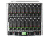
HP BladeSystem c7000 Enclosure
Quick Setup Instructions
Part Number 411762-403