HP D5970A HP Netserver LT 6000r Installation Guide
HP D5970A - NetServer - LCII Manual
 |
View all HP D5970A manuals
Add to My Manuals
Save this manual to your list of manuals |
HP D5970A manual content summary:
- HP D5970A | HP Netserver LT 6000r Installation Guide - Page 1
HP NetServer LT 6000r Installation Guide HP Part Number D9143-90000 Printed in February 2000 - HP D5970A | HP Netserver LT 6000r Installation Guide - Page 2
for the use or reliability of its software on equipment that is not furnished by guide is for the person who installs, administers, and troubleshoots LAN servers. Hewlett-Packard Company assumes you are qualified in the servicing of computer equipment and trained in recognizing hazards in products - HP D5970A | HP Netserver LT 6000r Installation Guide - Page 3
System Info Menu 15 Component Info Menu 16 Adjust Contrast Menu 17 Hard Disk Drive LED Indicators 17 Indicators and Controls behind the Front Bezel 18 Rear of the Chassis 18 LEDs at the Rear of the Chassis 19 Connecting the HP NetServer to AC Power 19 Power On and Power Off Procedures 20 - HP D5970A | HP Netserver LT 6000r Installation Guide - Page 4
HP NetRAID 34 Selecting SCSI Devices 34 Drive Mirroring 35 Boot Device Priority 35 Hot Swap Drive the Drive for Installation 39 Installing Hot-Swap Drives 40 Removing Hot-Swap Drives 41 Boot Priority 52 Tested PCI Boards and Drivers 52 Installing Accessory Boards 53 Installing an Accessory - HP D5970A | HP Netserver LT 6000r Installation Guide - Page 5
72 Replace the System Board Assembly 74 Setting the Processor Speed 75 Upgrading the Firmware 76 Testing the Processor 76 Re-Installing the NOS 76 Removing a Processor Module 76 8 Mounting the HP NetServer in an HP Rack System/E or Rack System/U 77 Introduction 77 Installation Basics - HP D5970A | HP Netserver LT 6000r Installation Guide - Page 6
116 NetServer Accessories 116 Server Management 117 Getting Help 117 Finding Information 118 Copying and Printing Information 119 Installing HP Information Assistant Software 119 Installing from the CD-ROM 120 12Troubleshooting 121 Troubleshooting Tools 121 Common Installation Problems 122 - HP D5970A | HP Netserver LT 6000r Installation Guide - Page 7
153 Notice for Korea 155 Notice for Taiwan 155 Declaration of Conformity (US, EU, Australia 156 Regulatory Notices - Product Safety 157 CD-ROM and Laser Safety Statements 157 Battery Statements 159 Noise and Ergonomic Statement 160 C Service, Support, Warranty, and Software License 161 vii - HP D5970A | HP Netserver LT 6000r Installation Guide - Page 8
Contents Service and Support 161 Warranty ...161 HP Software Product License Agreement 161 Non-Nuclear Usage 163 D Transporting the HP NetServer 165 Tools Required 165 Installation Instructions 165 Index...171 viii - HP D5970A | HP Netserver LT 6000r Installation Guide - Page 9
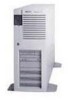
Guidelines This section provides guidelines for installing the HP NetServer LT 6000r. Carefully read through this section before installing the NetServer. Figure 1-1. HP NetServer LT 6000r WARNING Do not open system board access panel while server is powered on and running. Doing so will - HP D5970A | HP Netserver LT 6000r Installation Guide - Page 10
Chapter 1 Setting Up the HP NetServer LT 6000r Rack Mount Installation Follow the setup is required to lift the server. Do not attempt to lift the NetServer by yourself. Failure to observer this warning could result in serious injury or damage to the NetServer. 2. Familiarize yourself with the - HP D5970A | HP Netserver LT 6000r Installation Guide - Page 11
Additional Processors. 5. Install PCI hot-plug and non-hot-plug accessory boards in the NetServer. Refer to Chapter 6, Installing Additional Boards. 6. Reconnect internal cables as needed. 7. Install the server in the rack. Refer to Chapter 8, Mounting the HP NetServer in an HP Rack System - HP D5970A | HP Netserver LT 6000r Installation Guide - Page 12
. Press the LT 6000r's power button, and press the eject button on the server's CD-ROM drive. Insert the HP NetServer Navigator CD-ROM disk, and close the drive. Press the Reset button. If the server fails to boot, follow the instructions given on the screen. Refer to Chapter 10, Configuring the - HP D5970A | HP Netserver LT 6000r Installation Guide - Page 13
Make any changes suggested in the advisories. 12. Configure Remote Management: If you plan to mange the NetServer remotely, refer to the HP NetServer Management Reference Guide for instructions. Select "Configure Remote Management" on the Navigator screen to configure Integrated Remote Assistant. 5 - HP D5970A | HP Netserver LT 6000r Installation Guide - Page 14
partitions the hard disk drive. Installation Assistant guides you through the NOS installation, and configures the NOS with the appropriate drivers for the HP-bundled configuration or the network interface cards on HP's Tested Configurations. ∗ Manual NOS Installation: Follow the instructions on the - HP D5970A | HP Netserver LT 6000r Installation Guide - Page 15
Refer to the HP NetServer Server Management Reference Guide, and install HP TopTools. 16. Refer to Information Assistant on the HP NetServer Online Documentation CD-ROM for more information about the LT 6000r. Also see Chapter 11, Information Assistant. 17. Test and troubleshoot as necessary. Refer - HP D5970A | HP Netserver LT 6000r Installation Guide - Page 16
- HP D5970A | HP Netserver LT 6000r Installation Guide - Page 17
. Front of the Chassis Figure 2-1 shows the LT 6000r. Figure 2-1. LT 6000r Bezel and Front Panel Console NOTE A small protective cover is provided on the HP NetServer's front bezel to cover the Power and Reset buttons. This cover prevents someone from accidentally powering down or resetting the - HP D5970A | HP Netserver LT 6000r Installation Guide - Page 18
control panel to prevent unauthorized use. Go to the Setup utility security menu to configure this feature. DC Power Switch and LED 10 Turns the HP NetServer on and off. This switch is under the protective door on the front panel. Push once to turn on, again to turn off. As long - HP D5970A | HP Netserver LT 6000r Installation Guide - Page 19
HP NetServer. This switch may be disabled by Secure mode. Status screen Reports system status. For details, see the following section: "Viewing System Information." Server as a processor module exceeding its operating temperature. If the failed component is redundant, the NetServer might still be - HP D5970A | HP Netserver LT 6000r Installation Guide - Page 20
Contrast menu is selected). Increase contrast (when Adjust Contrast menu is selected). NOTE As long as the NetServer is plugged into its power source, the display buttons and menus will operate when the NetServer is powered down or hung,. During POST (power-on self-test), the buttons and menus are - HP D5970A | HP Netserver LT 6000r Installation Guide - Page 21
in stand-by or power-save mode. The AC line is unplugged or the power supply has failed (see Chapter 12, Troubleshooting). Main Menu This is the status screen default display: HP NetServer LT 6000r 1. To reach the main menu from this default screen, press the Enter button. NOTE The status screen - HP D5970A | HP Netserver LT 6000r Installation Guide - Page 22
from the Main Menu. The first two lines of the log appear on the NetServer's front panel display: ****Event Log**** >008! POST Error 2. Use the arrow brief summary of a log entry, including the log entry number. An "!" on a log entry means the problem is current. 3. To read the complete log for an - HP D5970A | HP Netserver LT 6000r Installation Guide - Page 23
. 3. Press Escape to return to the Main Menu. System Info Menu The System Info menu displays the HP NetServer's configuration information. Information includes the number, speed, and type of CPUs, cache information, and the amount of RAM on each memory board. 1. Select System Info from the Main - HP D5970A | HP Netserver LT 6000r Installation Guide - Page 24
indicates the CPU number. 3. Press Escape to return to the Main Menu. Component Info Menu To see the NetServer chassis' part numbers and serial numbers: 1. Select Asset Tag: AAAAAAAAAAAAAA Product Part: nnnn-nnnn Product Serial AAAAAAAAAAAAAA Chassis Part: nnnn nnnn Chassis Serial: AAAAAAAAAAAAAA - HP D5970A | HP Netserver LT 6000r Installation Guide - Page 25
for status and one for activity. You can view these LEDs on the LT 6000r with the bezel open or closed. For more information on hard drives, see Chapter 4, Installing Mass Storage Devices. Light pipes on the module transmit light to the indicators from LEDs on the inside of the hot-swap - HP D5970A | HP Netserver LT 6000r Installation Guide - Page 26
are visible only when the bezel is open or removed: l CD ROM l Flexible Disk Drive l Power Supplies Rear of the Chassis The LT 6000r's rear panel includes communications ports, AC power receptacles, and processor fans (see Figure 2-3). In addition, all hot plug PCI slots have corresponding LED - HP D5970A | HP Netserver LT 6000r Installation Guide - Page 27
For more information on PCI Hot Plug boards, see Chapter 6, Installing Additional Boards. Connecting the HP NetServer to AC Power When you connect the NetServer to an AC power source, the server temporarily draws additional current. This occurs even when the system is in standby mode. This "inrush - HP D5970A | HP Netserver LT 6000r Installation Guide - Page 28
Follow these circuit breaker recommendations before installing the server at your site: • In North America, use a 20-amp-minimum circuit with one NEMA AB1 class 14B breaker for each 16-amp Power Distribution Unit (PDU). • In Europe: ◊ For a single HP NetServer in a rack, use a 15-amp-minimum circuit - HP D5970A | HP Netserver LT 6000r Installation Guide - Page 29
instructions in your network operating system (NOS) documentation to shut down all networking software and applications. 3. Press the Power switch to shut down the NetServer. See Figure 2-3. Normally, this completes the procedure. Sleep States (ACPI) Sleep states are available if your NOS supports - HP D5970A | HP Netserver LT 6000r Installation Guide - Page 30
NOS may provide programming features to add more sleep states, to change the activation time for each state, and to shutdown or wake up the HP NetServer at certain times, depending on the way the NOS interface is programmed. This option can be provided through the TopTools Remote Control card (Wake - HP D5970A | HP Netserver LT 6000r Installation Guide - Page 31
3 Opening and Closing the HP NetServer Introduction This chapter explains how to open the LT 6000r bezel, and how to open and close the system board and accessory board access panels. Opening the Bezel Open the LT 6000r's bezel from the right-hand side of the server, and swing it out as shown in - HP D5970A | HP Netserver LT 6000r Installation Guide - Page 32
Chapter 3 Opening and Closing the HP NetServer Opening and Closing the System Board Access Panel This Figure 3-2. System Board Access Panel Location WARNING Always properly shutdown and power off the NetServer before you open the system board access panel. Refer to your network operating system - HP D5970A | HP Netserver LT 6000r Installation Guide - Page 33
the HP NetServer 1. Log off all users, and shut down the operating system according to your NOS instructions. WARNING The rack's anti-tip foot must be extended to prevent the rack from tipping over when you slide out the NetServer. 2. Power off the NetServer. When you power off the server, the - HP D5970A | HP Netserver LT 6000r Installation Guide - Page 34
Chapter 3 Opening and Closing the HP NetServer Figure 3-4. Rack Release WARNING Never attempt its components. 5. Before opening the system board access panel, unplug all power cords from the NetServer's rear panel. All power cords must be unplugged before you open the system board access panel - HP D5970A | HP Netserver LT 6000r Installation Guide - Page 35
Chapter 3 Opening and Closing the HP NetServer Figure 3-5. Open and Closed Positions on System Board Access Panel Handle 7. Slide the two panel latches toward the handle, and pull open the access panel, - HP D5970A | HP Netserver LT 6000r Installation Guide - Page 36
Chapter 3 NOTE Opening and Closing the HP NetServer The system board access panel is supported by one hydraulic spring. This spring supports the weight of the system board. four PCI hot-plug slots. For instructions on how to install PCI boards, refer to Chapter 6, Installing Additional Boards. 28 - HP D5970A | HP Netserver LT 6000r Installation Guide - Page 37
Chapter 3 Opening and Closing the HP NetServer Figure 3-7. Accessory Board Access Panel WARNING Do not leave the accessory board access panel open for more than 30 minutes while the NetServer is powered on. Doing so might cause the server to overheat. To open and close the accessory board - HP D5970A | HP Netserver LT 6000r Installation Guide - Page 38
Accessory Board Access Panel, Exposing Slots 2 through 6 3. Close the accessory board access panel. 4. Mount the server in the rack. Refer to Chapter 8, Mounting the HP NetServer in an HP Rack System/E or Rack System/U, and Chapter 13, Alternative Rack Mounting. 5. Reconnect all power cords and - HP D5970A | HP Netserver LT 6000r Installation Guide - Page 39
Chapter 3 Opening and Closing the HP NetServer Accessing PCI Slot 1 To access PCI Slot 1: 1. Shut down and power off the NetServer. 2. Disconnect all power cords and cables. 3. Remove the NetServer from the rack. NOTE Slot 1 uses a special PCI tray for installing certain accessory boards. Some - HP D5970A | HP Netserver LT 6000r Installation Guide - Page 40
- HP D5970A | HP Netserver LT 6000r Installation Guide - Page 41
NetServer is also equipped with a built-in CD-ROM and a floppy diskette drive. One SCSI channel, Channel A, supports the hot-swap cage. Another SCSI channel, Channel B, supports right. The embedded controller is assigned ID 07. The SAF-TE processor on the hot-swap cage is assigned ID 05. CAUTION Do - HP D5970A | HP Netserver LT 6000r Installation Guide - Page 42
guide on the following HP web site: http://www.hp.com/go/netserver/ Selecting SCSI Devices Hot-Swap Hot-swap mass storage consists of low-profile (1-inch) drives. Use only HP Ultra-2 (LVD) SCSI 3.5-inch hard disk drives. HP hot-swap drives drives are not supported when the LT 6000r operates in HP - HP D5970A | HP Netserver LT 6000r Installation Guide - Page 43
with three or four drives. To configure the LT 6000r as RAID, press [F2] to enter the Setup Utility when the NetServer boots, and enable NetRAID. Configure the RAID level according to the instructions given in Integrated HP NetRAID Controller Configuration Guide. Boot Device Priority By default - HP D5970A | HP Netserver LT 6000r Installation Guide - Page 44
Chapter 4 Installing Mass Storage Devices Hot Swap Drive Bay Addresses The hot-swap cage is addressed from left to right as ID 00, ID 01, ID 02, and ID 03 as shown in Figure 4-1. The NetServer's default boot sequence starts at ID 00. Figure 4-2 shows the location of the external SCSI connector on - HP D5970A | HP Netserver LT 6000r Installation Guide - Page 45
the antistatic bag, handle it only by the frame. Do not touch the electrical components. Place the drive on the anti-static bag whenever you set it down. Hard disk drives are very susceptible to mechanical shock and can be damaged by a drop as short as one-quarter of an inch. Take care - HP D5970A | HP Netserver LT 6000r Installation Guide - Page 46
Chapter 4 Installing Mass Storage Devices Locking latch (Push in, lift up, and pull out) Figure 4-3. Locking Latch Location 2. Using your fingers, pull out the filler panel. NOTE Leave the filler panels in place unless you are installing a SCSI device. They are required for proper ventilation. - HP D5970A | HP Netserver LT 6000r Installation Guide - Page 47
Chapter 4 Installing Mass Storage Devices Readying the Drive for Installation To ready the drive for installation, press in the locking latch, and pull the ejector handle as far out the handle. Locking latch (pull up on ejector handle to release) Figure 4-5. Readying the Drive for Installation 39 - HP D5970A | HP Netserver LT 6000r Installation Guide - Page 48
cage (Figure 4-6) until it seats into its connector. CAUTION Be careful not to damage the light pipes as you insert the drive. They are very fragile. Figure 4-6. Installing a Drive into the Hot-Swap Cage 2. Press in the ejector handle until you feel the locking latch click into place. Closing the - HP D5970A | HP Netserver LT 6000r Installation Guide - Page 49
drive to stop spinning and for the drive heads to park. 4. Using your hand to support the bottom of the drive, slowly pull out the drive in a straight and forward direction. Do not let the drive fall. 5. Place the drive of the drive. See the "Removing a Filler Panel" section for instructions. NOTE - HP D5970A | HP Netserver LT 6000r Installation Guide - Page 50
- HP D5970A | HP Netserver LT 6000r Installation Guide - Page 51
explains how to add memory to the HP NetServer LT 6000r. The NetServer is shipped from the factory with 256 DIMMs in the appropriate sockets. Up to 8 GB of memory can be installed in the NetServer. Figure 5-1. System Board Memory Sockets Memory Guidelines • Use only DIMMs of the following sizes: - HP D5970A | HP Netserver LT 6000r Installation Guide - Page 52
only HP-supported DIMMs. Tools Required The following tools are required for DIMM removal and installation: l An antistatic service kit server. 1. Log off all users, and shut down the network operating system according to your NOS instructions. 2. Power off the NetServer according to instruction - HP D5970A | HP Netserver LT 6000r Installation Guide - Page 53
Chapter 5 Installing Additional Memory WARNING Always disconnect the power cords before opening the system board access panel to avoid exposure to high energy levels that might damage equipment or cause personal injury. Disconnect any telephone cables to avoid exposure to shock hazard from - HP D5970A | HP Netserver LT 6000r Installation Guide - Page 54
, replace it now. 10. Close the system board access panel according to the instructions in Chapter 3, Opening and Closing the HP NetServer. 11. Replace the power cords and cables. 12. Restore the NetServer to normal operation. Removing DIMMs You may need to remove a DIMM to downsize your memory - HP D5970A | HP Netserver LT 6000r Installation Guide - Page 55
Chapter 5 Installing Additional Memory 2. Power off the NetServer according to instruction in Chapter 2, Controls, Indicators, and Ports. WARNING The power supply will continue to provide standby current to the NetServer. 3. Slide out the server from the rack. CAUTION The power supply will - HP D5970A | HP Netserver LT 6000r Installation Guide - Page 56
- HP D5970A | HP Netserver LT 6000r Installation Guide - Page 57
Boards Introduction This chapter explains how to install PCI accessory boards into the HP NetServer LT 6000r PCI slots. The PCI slots are located on the I/O I/O board accommodates six PCI accessory boards. Each slot supports standard PCI boards; Slots 3, 4, 5, and 6 support the Hot-Plug option. 49 - HP D5970A | HP Netserver LT 6000r Installation Guide - Page 58
, which contain cache memory DIMM used by the embedded RAID controller (Intel i960RN I/O processor); which is 64 MB standard and can be upgraded to 128 MB. Guidelines When installing accessory boards in the HP NetServer LT 6000r, observe the following guidelines: WARNING Never add or remove a PCI - HP D5970A | HP Netserver LT 6000r Installation Guide - Page 59
the following: ◊ To ensure that the correct PCI accessory board software drivers are installed. ◊ To verify that the board is operating correctly. If non-hot-plug supported boards are installed in these slots, the hot-plug feature is disabled. NOTE Refer to the HP NetServer Navigator CD-ROM for - HP D5970A | HP Netserver LT 6000r Installation Guide - Page 60
10, Configuring the HP NetServer. Tested PCI Boards and Drivers For a list of tested PCI accessory boards, check the Configuration Assistant on the HP NetServer Navigator CD-ROM or look for the Hardware Tested Products List link for the LT 6000r under HP NetServer Service and Support for the NOS - HP D5970A | HP Netserver LT 6000r Installation Guide - Page 61
Chapter 6 Installing Additional Boards For current PCI Hot-Plug information about NOS support and the availability of PCI Hot-Plug compliant drivers, search for pcihotplug on HP's website at: http://www.hp.com/netserver/products/LT 6000r Installing Accessory Boards NOTE To perform a hot add or a - HP D5970A | HP Netserver LT 6000r Installation Guide - Page 62
or damage the system. 1. Log off users, and shut down the NetServer according to your NOS instructions. 2. Power off the NetServer. 3. Disconnect the power cords and cables and, if necessary, label each one to support reassembly. NOTE The power supply modules will continue to provide standby - HP D5970A | HP Netserver LT 6000r Installation Guide - Page 63
the full length of the board with its slot and position it into the slot. NOTE For instructions on installing a PCI accessory board in Slot 1, see the subsection "Installing an Accessory Board into with the PCI lever and retainer. Full-size boards are supported when seated in the card guides. 55 - HP D5970A | HP Netserver LT 6000r Installation Guide - Page 64
and restart the network operating system, according to your NOS instructions. NOTE All Hot Swap slots power on when the locking levers are closed, and the HP NetServer recognizes all new boards when it reboots, regardless of the presence of a driver or a PCI Hot-Plug Utility. If the PCI accessory - HP D5970A | HP Netserver LT 6000r Installation Guide - Page 65
board software drivers are loaded, and verify its correct operation. 18. Restore the NetServer to tray is used specifically for installing a board in Slot 1 when the NetServer is mounted in the server is mounted in a rack. l Full-size accessory boards should be installed in the tray when the server is - HP D5970A | HP Netserver LT 6000r Installation Guide - Page 66
board from the tray. Accessory Board Installation Instructions 1. Log off users and shut down the NetServer according to your NOS instructions. 2. Power off the NetServer. 3. Disconnect the power cords and cables and, if necessary, label each one to support re-assembly. NOTE The power supply - HP D5970A | HP Netserver LT 6000r Installation Guide - Page 67
from the rack, and you must remove both slides from the chassis before you can open the access panel. It is recommended to remove the NetServer from the rack before installing a full-size accessory board in the accessory board tray. Read label on accessory board access panel before installing the - HP D5970A | HP Netserver LT 6000r Installation Guide - Page 68
Chapter 6 When seating a Half-size, half-height board into its slot, push in the board here with one hand. Installing Additional Boards Half-size accessory board edge fits under this tang. Half-size, half-height accessory board While pushing in the board with one hand, push in the tray with the - HP D5970A | HP Netserver LT 6000r Installation Guide - Page 69
Additional Boards Ensure that this side of the tray is aligned with the left-hand metal guide inside the chassis. Ensure that this side of the tray is aligned with the right-hand metal guide inside the chassis. Ensure that lower door is open when inserting tray and accessory board. Figure - HP D5970A | HP Netserver LT 6000r Installation Guide - Page 70
Chapter 6 Installing Additional Boards Accessory board (full-size) edge fits under these tangs. After seating the board in the tray, push the tray into the chassis so that the board's edge connector inserts into the slot. Figure 6-8. Seating the Accessory Board into Tray (Full-Size Board) 8. Slide - HP D5970A | HP Netserver LT 6000r Installation Guide - Page 71
or a connection to the I/O board, ensure that the cable is properly connected. Refer to the documentation that came with the accessory board for instructions. 13. Reconnect the power cords and cables. 14. Power on the NetServer and restart the network operating system, according to your NOS - HP D5970A | HP Netserver LT 6000r Installation Guide - Page 72
hot-plug compliant drivers. Then initialize the driver if it is not done automatically. For current PCI Hot-Plug information about NOS support, and the PCI hot-plug accessory board portfolio for the LT 6000r, search for PCI Hot Plug on HP's web site at: http://netserver.hp.com/netserver/products/ To - HP D5970A | HP Netserver LT 6000r Installation Guide - Page 73
is powered on, refer to the PCI Hot-Plug Help file on the HP NetServer Navigator CD-ROM. Removing a Hot-Plug Accessory Board To remove a hot-plug board from the NetServer, which is not powered on, follow these instructions: 1. Open the accessory board access panel. 2. Open the locking lever and - HP D5970A | HP Netserver LT 6000r Installation Guide - Page 74
- HP D5970A | HP Netserver LT 6000r Installation Guide - Page 75
Introduction The LT 6000r comes equipped with one primary processor module and one corresponding voltage regulator module (VRM) installed on the system board assembly. Up to five additional processors and corresponding VRMs can be added. All processor modules must operate at the same clock frequency - HP D5970A | HP Netserver LT 6000r Installation Guide - Page 76
the HP NetServer Navigator CD-ROM. After installing processors, boot with this CD-ROM to update the BIOS. Configuration Guidelines Use the following guidelines when installing additional processor modules in the LT 6000r: • Use only processor module upgrade kits with the same HP product number - HP D5970A | HP Netserver LT 6000r Installation Guide - Page 77
the power cable is disconnected. Remove the System Board Assembly 1. Open the system board access panel according to the instructions in Chapter 3, Opening and Closing the HP NetServer. NOTE If the NetServer is in a rack, slide it out before opening the access panel. Be sure to pull out the rack - HP D5970A | HP Netserver LT 6000r Installation Guide - Page 78
Release Latch Locations The system board assembly is heavy. Use the two handles on each side of the top processor cover to lift the system board from the NetServer chassis. CAUTION Wear a wrist strap and use a static-dissipating work surface connected to the chassis when handling components. 70 - HP D5970A | HP Netserver LT 6000r Installation Guide - Page 79
3. Use the handles located on the top processor cover to lift the system board assembly from the NetServer chassis. Figure 7-3. Removing the System Board Assembly from the Access Panel 4. Place the assembly on an antistatic pad. 5. Unpack the processor shipping box and check the contents against - HP D5970A | HP Netserver LT 6000r Installation Guide - Page 80
Chapter 7 Installing Additional Processors Install the Processor 1. Loosen the thumbscrew and remove the access cover on the processor cage. Figure 7-4. Loosen Thumbscrew on Processor Cage Access Cover 2. Locate the slot where you will install the new processor, open the latches on the terminator - HP D5970A | HP Netserver LT 6000r Installation Guide - Page 81
up for Slots 1, 2, and 3; and down for Slots 4, 5, and 6. 6. Slide the processor into the slot until it's fully seated. 7. Close the latches to seat the processor firmly into its connector. 8. Replace the processor cage access cover, and tighten the thumbscrew. 9. Install the corresponding VRM by - HP D5970A | HP Netserver LT 6000r Installation Guide - Page 82
Chapter 7 Installing Additional Processors Figure 7-6. Installing a VRM CAUTION Do not touch the VRM components as on them. 2. Close the system board access panel according to the instructions in Chapter 3, Opening and Closing the HP NetServer. 3. Reconnect the power and cables. 4. Restore the - HP D5970A | HP Netserver LT 6000r Installation Guide - Page 83
from the system switch located on the system board. NOTE Some processor speeds may not be supported. For latest information, visit the HP website: http://www.hp.com/go/netserver Figure 7-7. System Switch Location Determine the processor speed from the following table, and set the system switch - HP D5970A | HP Netserver LT 6000r Installation Guide - Page 84
after installing the new processor. The NetServer detects additional processors automatically. However, HP recommends using the HP NetServer Navigator CD-ROM that comes with the processor upgrade kit to ensure that you have the latest drivers and information. Testing the Processor After you power - HP D5970A | HP Netserver LT 6000r Installation Guide - Page 85
8 Mounting the HP NetServer in an HP Rack System/E or Rack System/U Introduction This chapter tells how to mount the HP NetServer LT 6000r in an HP Systems rack. Figure 8-1. HP Rack System/E and Rack System/U Rack Features 77 - HP D5970A | HP Netserver LT 6000r Installation Guide - Page 86
efficiency. For more details, see the HP NetServer Rack Installation Road Map and the HP NetServer Rack Assembly and Cabling Reference Guide. NOTE Mounting the LT 6000r in its rack may or may not be the final step in the installation procedure. If the server is completely configured by the vendor - HP D5970A | HP Netserver LT 6000r Installation Guide - Page 87
Plan the placement of equipment in the rack to make sure that this problem does not occur. Mount the heaviest components in the bottom of the rack the slides on the rack columns when using the rack installation template. HP NetServer Rack Mount Parts List Makes sure that the rack-mount kit that - HP D5970A | HP Netserver LT 6000r Installation Guide - Page 88
Rack Mounting, for alternative rack mount instructions. NOTE Use the HP Rack Assistant software to determine where to mount the HP NetServer in the rack. CAUTION To ensure the same rack space that the server will occupy. (The template covers an area four EIA units high, the same height the 80 - HP D5970A | HP Netserver LT 6000r Installation Guide - Page 89
Chapter 8 Mounting the HP NetServer in an HP Rack System/E or Rack System/U server requires.) The template directs you to the second and fourth holes on the rack column that are used for mounting the slide. Mark these holes - HP D5970A | HP Netserver LT 6000r Installation Guide - Page 90
Chapter 8 Mounting the HP NetServer in an HP Rack System/E or Rack System/U 1. Loosen the adjustment knob on one slide, insert the knob so that the slide is secure, and will not unseat itself when mounting the NetServer on the slides. 5. Repeat Steps 1 through 4 to install the other slide. 82 - HP D5970A | HP Netserver LT 6000r Installation Guide - Page 91
Chapter 8 Mounting the HP NetServer in an HP Rack System/E or Rack System/U Step 3: Mount the LT 6000r in the Rack This step explains how to mount the LT 6000r into the rack. - HP D5970A | HP Netserver LT 6000r Installation Guide - Page 92
Chapter 8 Mounting the HP NetServer in an HP Rack System/E or Rack System/U 2. With the help of at least one other person, lift the server by its four handles, and position it directly over the extended slides. NOTE The arrows on the sides of the LT 6000r must line up - HP D5970A | HP Netserver LT 6000r Installation Guide - Page 93
8 Mounting the HP NetServer in an HP Rack System/E or Rack System/U 4. Pull the LT 6000r forward onto the slides until the nib on the blue latch snaps into the square hole on the slide. This ensures that the mounting hooks are properly seated inside the chassis, and that the server is locked into - HP D5970A | HP Netserver LT 6000r Installation Guide - Page 94
will lock into place. Push the server to the first notch on the blue rack latch position closest to the bezel (see Figures 8-9 and 8-10). The second latch position is used when mounting the HP NetServer in a non-HP rack. WARNING Do not slide the NetServer into rack when the bezel is in the closed - HP D5970A | HP Netserver LT 6000r Installation Guide - Page 95
Chapter 8 Mounting the HP NetServer in an HP Rack System/E or Rack System/U Figure 8-9. Release the Slide Lock Figure 8-10. Rack Latch Close-Up (View with Bezel Removed) 87 - HP D5970A | HP Netserver LT 6000r Installation Guide - Page 96
panel to prevent the server from being released from the rack. 8. Close the bezel. 9. Refer to the Rack Mount Cabling Reference Guide on the HP NetServer Navigator CD-ROM for information about installing the LT 6000r's Cabling Management Arm and other cabling instructions. Step 4: Install the Cable - HP D5970A | HP Netserver LT 6000r Installation Guide - Page 97
Chapter 8 Mounting the HP NetServer in an HP Rack System/E or Rack System/U Figure 8-12. Installing the Cable Management Arm to the NetServer Rear Panel 2. Install the rack bracket to the left-hand rear column on the rack as shown in Figure 8-13. The bracket's position should be - HP D5970A | HP Netserver LT 6000r Installation Guide - Page 98
/U Figure 8-13. Installing the Cable Management Arm to the Left-Hand Rack Column 3. Refer to the LT 6000r Rack Assembly and Cabling Reference Guide on the HP NetServer Navigator CD-ROM for information about cable routing. Step 5: Continue with the Rack Installation Process After you install the - HP D5970A | HP Netserver LT 6000r Installation Guide - Page 99
9 Connecting the Monitor, Keyboard, and Mouse Introduction This chapter explains how to connect a monitor, keyboard, mouse, and uninterruptible power supply (UPS) to the HP NetServer LT 6000r. Connecting the Monitor, Keyboard, Mouse, and UPS To connect the monitor, keyboard, mouse, and UPS to the - HP D5970A | HP Netserver LT 6000r Installation Guide - Page 100
Chapter 9 Connecting the Monitor, Keyboard, and Mouse Figure 9-1. HP NetServer LT 6000r Ports NOTE If you have a console switch box, refer to the switch box's user guide for instructions on connecting the monitor, keyboard, and mouse. 2. Connect each of the power supply module's power cords to - HP D5970A | HP Netserver LT 6000r Installation Guide - Page 101
the Setup Utility prior to installing the NOS. HP NetServer Navigator CD-ROM Use the HP NetServer Navigator CD-ROM (Navigator) to perform configuration functions, and create diskettes containing necessary tools and drivers. 1. Insert the CD-ROM in the CD drive of a desktop or laptop computer. If the - HP D5970A | HP Netserver LT 6000r Installation Guide - Page 102
HP-tested peripherals and accessories (see the Tested Configurations in Guide to Configure NetServer). 7. Review "Diskette Library." You can review the current diskette library by title and version numbers and create diskettes that contain the necessary tools and drivers. 8. Review "Troubleshooting - HP D5970A | HP Netserver LT 6000r Installation Guide - Page 103
Number Status Report The Status Report for your specific HP NetServer Navigator CD-ROM describes in detail any software updates between this version of the CD-ROM and the previous version. To obtain Release Notes or a Status Report, go to: http://netserver.hp.com/netserver/support/compatibility - HP D5970A | HP Netserver LT 6000r Installation Guide - Page 104
the HP NetServer NOTE Using the low profile CD-ROM drive is slightly different from full-height units. The disk drawer will spring out only part way when you press the eject button. You must manually open and close the drawer. 4. If the CD-ROM fails to autorun, follow the diagnostic instructions - HP D5970A | HP Netserver LT 6000r Installation Guide - Page 105
the Setup Utility section later in this chapter. Running Configuration Assistant and Installation Assistant Insert the HP NetServer Navigator CD-ROM into the CD-ROM drive. If the system fails to start, follow the instructions on the screen. 1. Set language, time, and date, if necessary. 2. Go to the - HP D5970A | HP Netserver LT 6000r Installation Guide - Page 106
Microsoft Windows NT Server on a factory-configured NetServer. Automated NOS installation will guide you through the NOS installation, set up the hard disk drive, and configure your NOS with appropriate drivers for HP-bundles configurations. This installation also loads the Local Support Tool onto - HP D5970A | HP Netserver LT 6000r Installation Guide - Page 107
32 MB DOS-based utility partition on the NetServer hard disk where HP Navigator will copy DiagTools, the BIOS Update utility, the Event Log Report utility, the Disk Array utility, the NIC Configuration utility, the Integrated Remote Assistant utilities, troubleshooting utilities, and other utilities - HP D5970A | HP Netserver LT 6000r Installation Guide - Page 108
selected the NOS, NOS version, and NOS installation mode (automated or manual), and after you have viewed the Configuration Advisories, the Custom Configuration . l Create Drivers Diskette(s): SCSI IDE HP NetRAID Adapter and video adapter drivers for Microsoft Windows NT 4.0 on HP NetServers. 100 - HP D5970A | HP Netserver LT 6000r Installation Guide - Page 109
Instructions: Select this option to save a copy of NOS installation instructions or manual, is Server, Configuration Assistant partitions and formats the hard disk drive, and Installation Assistant guides you through the NOS installation, and configures the NOS with the appropriate drivers for the HP - HP D5970A | HP Netserver LT 6000r Installation Guide - Page 110
for Servers HP TopTools for Servers is a new browser-based management software that provides remote administration and monitoring of critical HP NetServer components. TopTools provides vital information for the fastest troubleshooting and proactive management of NetServers. Processors, memory - HP D5970A | HP Netserver LT 6000r Installation Guide - Page 111
installed to help your service provider troubleshoot your system. TopTools is located on the HP TopTools CD-ROM included with the server. l See the HP NetServer Management Reference Guide for detailed installation instructions. l You can also download the TopTools software and documentation from the - HP D5970A | HP Netserver LT 6000r Installation Guide - Page 112
-redirection software from Symantic Corporation that lets you take control of Microsoft Windows NT Servers across the network or over a modem. Refer to the HP NetServer Online Documentation CD-ROM for details or the HP TopTools Remote Control User Guide. NetServer Utilities NetServer Utilities - HP D5970A | HP Netserver LT 6000r Installation Guide - Page 113
To reach the Setup Utility, boot or reboot the server. After the first boot messages are displayed, the . If you do not press [F2], the HP NetServer boots normally. Menu Bar The Setup Utility menu Use this menu to disable Smart Interrupt Routing, and manually set the PCI board's IRQs. You can set - HP D5970A | HP Netserver LT 6000r Installation Guide - Page 114
type or add an IDE hard drive to HP NetServer's configuration. This would include selecting the hard disk drive's characteristics, manually or automatically, and selecting which drive will be the primary master or slave, the CD-ROM, or the IDE hard disk drive. ◊ Processor/Memory Settings: Use this - HP D5970A | HP Netserver LT 6000r Installation Guide - Page 115
Chapter 10 Configuring the HP NetServer Using the Setup Screens Online help explains the settings displayed on the Setup Utility screens. Instructions are also provided for navigating between the screens, and entering or changing the setup data. l Press the right-arrow and left-arrow keys to move - HP D5970A | HP Netserver LT 6000r Installation Guide - Page 116
The user password is limited in access once booted. To configure the HP NetServer for passwords, and to require a password during boot-up, perform the following procedure: 1. If not already in the Setup Utility, boot or reboot the server, and press [F2] when prompted. 2. Use the right or left-arrow - HP D5970A | HP Netserver LT 6000r Installation Guide - Page 117
, but can choose to skip setting the user password. NOTE You must set the administrator password before changing a user password or configuring the HP NetServer to boot with a password. 4. Press Enter to enter a new password or change the old one. A pop-up menu appears: "Set Power-On Password - HP D5970A | HP Netserver LT 6000r Installation Guide - Page 118
from "Disabled" to "Enabled" in the Network Server Mode field. Setting this mode to "Enabled" causes the HP NetServer to prompt for a password when booting from a diskette or a CD-ROM, but will not require a password when booting from a hard disk drive. The power switch and keyboard will remain - HP D5970A | HP Netserver LT 6000r Installation Guide - Page 119
HP NetServer's internal mass storage devices. To do this, follow these instructions: 1. Select "Boot Settings" from the Configuration menu, and press Enter. The Boot Settings screen appears, similar to the following: Floppy check: Summary screen: Quick Boot mode: Boot Device Priority Hard Drive - HP D5970A | HP Netserver LT 6000r Installation Guide - Page 120
10 Configuring the HP NetServer 1. [Bootable Cards] 2. [#30 ID01 LUN0 HP 3. [#30 ID01 LUN0 HP 4.2GB A] 4.2GB A] The server attempts to boot the NOS on the first hard drive (or DAC or SCSI board) found in the list. If no NOS is found, the system tries to boot from the next hard drive in the list - HP D5970A | HP Netserver LT 6000r Installation Guide - Page 121
Chapter 10 Configuring the HP NetServer Figure 10-2. System Board Configuration Switch 3. Close the system board access panel and power on the server. 4. Let the server boot. 5. After booting, shut down and power off the server and open the system board access panel. 6. Reset Switch 5 from the ON - HP D5970A | HP Netserver LT 6000r Installation Guide - Page 122
disk or change hard disk parameters: ◊ Select an adapter from the list in the main menu. ◊ Select "Drive Selections." ◊ Select the hard disk to format. ◊ Select "Format." For more details, including default settings, refer to "Information Assistant" on the HP NetServer Online Documentation CD-ROM - HP D5970A | HP Netserver LT 6000r Installation Guide - Page 123
General Information This menu button provides general information about the capabilities of the Information Assistant application. Specific topics are: l About the HP NetServer Online Documentation CD-ROM l Accessing Printable and Localized Files in Information Assistant l Service and Support 115 - HP D5970A | HP Netserver LT 6000r Installation Guide - Page 124
products is also accessible via this button. NetServer Accessories This menu button provides access to information about various NetServer accessories. Specific topics are: l HP NetRAID l Processor and System l Memory l Network Interface Cards (NICs) l Mass Storage and SCSI l Rack and Cabling Guides - HP D5970A | HP Netserver LT 6000r Installation Guide - Page 125
11 Information Assistant Server Management This menu button provides access to various NetServer management products. Representative topics are: l HP TopTools l HP TopTools Remote Control l HP NetServer Assistant l HP OpenView Informational files about some of these products are provided as - HP D5970A | HP Netserver LT 6000r Installation Guide - Page 126
and topic in Information Assistant for the selected product. The Map enables you to view the contents a Product button. The Product button presents a product or group of products for of Contents for the selected product from which a subtopic topic of the product book. After selecting the print - HP D5970A | HP Netserver LT 6000r Installation Guide - Page 127
Assistant for use in other applications, such as word processors, by copying text onto the Windows Clipboard and pasting printer. Installing HP Information Assistant Software HP Information Assistant runs on a PC running Windows 3.1, Windows 95 and 98, or Windows NT. Install it from the HP NetServer - HP D5970A | HP Netserver LT 6000r Installation Guide - Page 128
Program Manager. 3. Insert the HP NetServer Online Documentation CD-ROM into the CD-ROM drive. 4. From Program Manager, select Run. 5. In the RUN window, type the following: drive: \INFOASST\setup where drive is the letter of the CD-ROM drive. 6. Follow the instructions that appear on your screen - HP D5970A | HP Netserver LT 6000r Installation Guide - Page 129
Tools If you are having problems installing your HP NetServer, there are a number of different tools available for troubleshooting: • HP NetServer Information Assistant (see Chapter 11) contains the following tools: ◊ Troubleshooting Information ◊ Part Information ◊ List of Error Messages - HP D5970A | HP Netserver LT 6000r Installation Guide - Page 130
you require assistance from Hewlett-Packard, see the HP NetServer Warranty and Service/Support Booklet or refer to the HP NetServer Online Documentation CD-ROM included with your product. Troubleshooting Sequence To troubleshoot an installation problem, do the following: • Check all cable and power - HP D5970A | HP Netserver LT 6000r Installation Guide - Page 131
server. b. Extend the HP NetServer out of the rack. c. Simplify the HP NetServer configuration to the minimum required: • Monitor • Keyboard • Mouse • 1 hard disk drive and 1 flexible disk drive • 1 flexible, and one hard disk drive electrical device (such as a printer) into the power outlet and - HP D5970A | HP Netserver LT 6000r Installation Guide - Page 132
actions to take. If the actions do not solve the problem, contact HP or your reseller. If there is no error message, follow these steps: 1. Check to ensure that the HP NetServer is configured correctly in the Setup Utility. 2. If the server still does not work, turn it off and remove all external - HP D5970A | HP Netserver LT 6000r Installation Guide - Page 133
the access panels and lock the system. f. Replace all power cords and cables. g. Power on the monitor. h. Power on the server. i. Check for error messages. 4. Copy DiagTools from the HP NetServer Navigator CD-ROM to diskette and run it from diskette. 5. Invoke the Event Log Report Utility from the - HP D5970A | HP Netserver LT 6000r Installation Guide - Page 134
Troubleshooting DiagTools You can create your own diskette of tools to diagnose components offline. A basic suite of tools checks key HP NetServer processors • memory modules • hard disk packs • flexible disks • keyboards • serial ports • parallel ports • video monitor • CD-ROM drives - HP D5970A | HP Netserver LT 6000r Installation Guide - Page 135
Chapter 12 Troubleshooting If you have TopTools remote management software installed and configured for use with DiagTools, you can accomplish any of the above tasks remotely. See the online documentation HP NetServer DiagTools Error Reference and User Guide for more information on DiagTools. - HP D5970A | HP Netserver LT 6000r Installation Guide - Page 136
access panel, plug in the power cords, and power on the HP NetServer. The following message appears. This configuration has been cleared. Set the Clear Config switch to the OFF position before rebooting. 7. Power off the server, disconnect the power cords, and open the system board access panel - HP D5970A | HP Netserver LT 6000r Installation Guide - Page 137
Chapter 12 Troubleshooting Password Problems If you have forgotten the password, your HP NetServer will function normally, but you will not be able to change the system configuration settings in the setup utility. To reset the password, follow these instructions: 1. Log off all users and shut down - HP D5970A | HP Netserver LT 6000r Installation Guide - Page 138
- HP D5970A | HP Netserver LT 6000r Installation Guide - Page 139
Rack Mounting Introduction This chapter tells how to mount the HP NetServer LT 6000r in an HP System Rack. a b c d a. 3-cornered columns b. Fan-only vent c. "HP Systems" name plate d. EIA units marked by triangles e. Anti-tip foot extends out front only e Figure 13-1. HP System Rack Features 131 - HP D5970A | HP Netserver LT 6000r Installation Guide - Page 140
efficiency. For more details, see the HP NetServer Rack Installation Road Map and the HP NetServer Rack Assembly and Cabling Reference Guide. NOTE Mounting the LT 6000r in its rack may or may not be the final step in the installation procedure. If the server is completely configured by the vendor - HP D5970A | HP Netserver LT 6000r Installation Guide - Page 141
Plan the placement of equipment in the rack to make sure that this problem does not occur. Mount the heaviest components in the bottom of the following tools are required: • 11mm nut driver or adjustable wrench • Torx-15 driver • Marking pen HP NetServer Rack Mount Parts List Makes sure that the - HP D5970A | HP Netserver LT 6000r Installation Guide - Page 142
the rack-mount template to mark out four EIA units for positioning the LT 6000r in the rack. NOTE Use the HP Rack Assistant software to determine where to mount the HP NetServer in the rack. CAUTION Be sure to compensate for any other components that might be mounted in the rack. Install these - HP D5970A | HP Netserver LT 6000r Installation Guide - Page 143
the template with the same rack space that the server will occupy. (The template covers an area four EIA units high, the same height the server requires.) The template directs you to two holes in location in case you ever need to mount the server in an HP Rack System/E or Rack System/U. 135 - HP D5970A | HP Netserver LT 6000r Installation Guide - Page 144
Chapter 13 Alternative Rack Mounting 3. Remove the lock nuts that secure the slide brackets to the slide. You will need two of these nuts from each slide to secure the slides to the inside columns of the rack. Store the other nuts as you did in Step 2. Step 3: Install the Slides in the Rack This - HP D5970A | HP Netserver LT 6000r Installation Guide - Page 145
Chapter 13 Alternative Rack Mounting Figure 13-5. Installing the Slides in the Rack NOTE To differentiate between both slides, the right-hand slide is marked with an R embossed on the outside; the left-hand slide is marked with an L. Arrows pointed up are embossed on the outside of each slide to - HP D5970A | HP Netserver LT 6000r Installation Guide - Page 146
Chapter 13 Alternative Rack Mounting Step 4: Mount the LT 6000r in the Rack This step explains how to mount the LT 6000r onto its slides in the rack. WARNING Ensure that the rack's anti-tip foot is fully extended out of the rack to prevent rack instability while mounting LT 6000r. Failure to do - HP D5970A | HP Netserver LT 6000r Installation Guide - Page 147
13 Alternative Rack Mounting 2. With the help of at least one other person, lift the server by its four handles, and position it directly over the extended slides (see Figure 13-7). NOTE Figure 13-7. Mounting the NetServer The arrows embossed on the sides of the LT 6000r must line up with the - HP D5970A | HP Netserver LT 6000r Installation Guide - Page 148
latch snaps into the square hole on the slide members. This ensures that the mounting hooks are properly seated inside the chassis, and that the server is locked into position on the slides. Figure 13-8. Latch Nib Inside Square Hole on Slide (View with Bezel Removed) 5. Remove the four handles from - HP D5970A | HP Netserver LT 6000r Installation Guide - Page 149
slide locks and push the mounted server into the rack. The server will lock into place. Push the server to the first notch on the blue rack latch position (see Figures 13-10 and 13-11). The second latch position is used when mounting the HP NetServer in a non-HP rack. WARNING Do not slide the - HP D5970A | HP Netserver LT 6000r Installation Guide - Page 150
Chapter 13 Alternative Rack Mounting Figure 13-10. Releasing the Slide Lock 142 - HP D5970A | HP Netserver LT 6000r Installation Guide - Page 151
Chapter 13 Alternative Rack Mounting Figure 13-11. Rack Latch Close-Up (View with Bezel Removed) 7. Open the bezel and turn the key lock on the right-hand side of the LT 6000r's front panel to prevent the server from being released from the rack. 8. Close the bezel. 143 - HP D5970A | HP Netserver LT 6000r Installation Guide - Page 152
the left rear column on the rack. Figure 13-12. LT 6000r Cable Management Arm Use these instructions to install the arm: 1. Install the chassis bracket to the left-hand rear panel of the NetServer as shown in Figure 13-13. a. Install two Torx 6-32 screws into the mounting holes on the - HP D5970A | HP Netserver LT 6000r Installation Guide - Page 153
rear panel Torx 6-32 screws Alternative Rack Mounting Chassis bracket Figure 13-13. Installing the Cable Management Arm to the NetServer Rear Panel 2. Install the rack bracket to the left-hand rear column on the rack as shown in Figure 13-14. The bracket's position should - HP D5970A | HP Netserver LT 6000r Installation Guide - Page 154
Rack Mounting Figure 13-14. Installing the Cable Management Arm to the Left-Hand Rack Column 3. Refer to the LT 6000r Rack Assembly and Cabling Guide on the HP NetServer Navigator CD-ROM for information about cable routing. Step 6: Continue with the Rack Installation Process After you install the - HP D5970A | HP Netserver LT 6000r Installation Guide - Page 155
Specifications The specifications listed below vary if you install a mass storage device in your server that has more stringent environmental limits. Make sure that the operating environment for your server 160Hz not supported not supported not supported not supported 3D Video Resolutions Resolution 512 x - HP D5970A | HP Netserver LT 6000r Installation Guide - Page 156
Appendix A Specifications Environment Thermal Temperature Operating Non-operating 5° to 35° C ft) Acoustic Emissions Sound level (LpA): < 58dBA Minimum Clearance The following data pertains to servicing the HP NetServer LT 6000r while it is mounted in the rack. Front 1 m (39 inches) Sides - HP D5970A | HP Netserver LT 6000r Installation Guide - Page 157
Appendix A Specifications Weight and Dimensions NOTE A fully-loaded HP NetServer LT 6000r can weigh up to 100 lbs (45 kgs). Follow local regulations and use one person for every 40 lbs (18 kgs) of NetServer weight when lifting it. Height Width Depth Weight Power Requirements 17.5 cm (7 inches) - HP D5970A | HP Netserver LT 6000r Installation Guide - Page 158
- HP D5970A | HP Netserver LT 6000r Installation Guide - Page 159
- Electromagnetic Compliance Your HP NetServer may fit into Class to other electrical equipment, including public safety services. Two levels of radio frequency energy are allowed domestic regulations. NOTE Check the label on your product to determine the level of operation. The label indicates - HP D5970A | HP Netserver LT 6000r Installation Guide - Page 160
Notice for United States For Products Labeled "Class A" This not installed and used in accordance with the instructions manual, may cause harmful interference to radio communications. Packard's system tests were conducted with HP-supported peripheral devices and HP shielded cables, such as those you - HP D5970A | HP Netserver LT 6000r Installation Guide - Page 161
les exigences du Réglement sur le matériel brouilleur du Canada. Notice for Japan The configuration of the NetServer you have purchased is in class A category. For Products Labeled "Class A" (Translation) This equipment is in the 1st Class category information technology equipment based on the - HP D5970A | HP Netserver LT 6000r Installation Guide - Page 162
Equipment (VCCI). Although aimed for residential area operation, radio interference may be caused when used near a radio or TV receiver. Read the instructions for correct operation. Power Line Harmonics (Japan) (Translation) This product conforms to the Power Line Harmonic guideline. 154 - HP D5970A | HP Netserver LT 6000r Installation Guide - Page 163
Appendix B Notice for Korea For Products Labeled "Class A" Regulatory Information (Translation) User Guide (Class A) Please note that this equipment has been approved for business purposes with regard to electromagnetic interference. If purchased in error for use in a residential - HP D5970A | HP Netserver LT 6000r Installation Guide - Page 164
Address: 10955 Tantau Avenue Cupertino, CA 95014-5040 USA declares, that the product Product Name: Model Number(s): Product Options: Network Server HP NetServer LT 6000r ALL conforms to the following Product Specifications: Safety: EMC: IEC 60950: 1991+A1 + A2 + A3 + A4/EN 60950: 1992 - HP D5970A | HP Netserver LT 6000r Installation Guide - Page 165
Health and Safety Act of 1968. To ensure proper use of this product, please read this instruction manual carefully and retain for future reference. Should the unit ever require maintenance, contact an authorized service location. Use of controls, adjustments or the performance procedures other than - HP D5970A | HP Netserver LT 6000r Installation Guide - Page 166
KLASSE 1" klassifiziert. Für den richtigen Gebrauch dieses Modells die Bedienungsanleitung sorgfältig durchlesen und als Referenz aufbewahren. Falls Probleme mit diesem Modell aufreten, die nächste "authorisierte ServicesVerrtetung" benachrichtigen. Um einen direkten Kontakt mit dem Laserstrahl zu - HP D5970A | HP Netserver LT 6000r Installation Guide - Page 167
CLASS 1 LASER PRODUCT LASSER KLASSE 1 PRODUKT This CD-ROM Drive Unit is classified as a CLASS 1 LASER PRODUCT. The CLASS 1 LASER PRODUCT label is located on the top of the drive. Bei diesem CD constructeur. Mettre au rebut les batteries usagées conformément aux instructions du fabricant. 159 - HP D5970A | HP Netserver LT 6000r Installation Guide - Page 168
- Germany Sound Pressure: LpA < 55 dB (A) am Arbeitsplatz, Beobachter Position (workplace, bystander position) normaler Betrieb (normal operation) nach DIN 45635 T. 19 (per ISO 7779) This product has not been evaluated for compliance with the ZH1/618 ergonomic requirements. 160 - HP D5970A | HP Netserver LT 6000r Installation Guide - Page 169
Support For all Service and Support information, see the HP NetServer Warranty and Service/Support Booklet included with your product. Warranty See the HP NetServer Warranty and Service/Support Booklet included with your product for all warranty and service/support information. HP Software Product - HP D5970A | HP Netserver LT 6000r Installation Guide - Page 170
Appendix C Service, Support, Warranty, and Software License a sale of any rights in the Software. HP's third party suppliers may protect their rights in the event of any violation of these License Terms. Copies and Adaptations. You may only make copies or adaptations of the Software for archival - HP D5970A | HP Netserver LT 6000r Installation Guide - Page 171
Appendix C Service, Support, Warranty, and Software License Non-Nuclear Usage HP NetServers are not specifically designed, manufactured or intended solely liable if Products or Support purchased by Customer are used for these applications. Customer releases HP and will hold HP harmless from all - HP D5970A | HP Netserver LT 6000r Installation Guide - Page 172
- HP D5970A | HP Netserver LT 6000r Installation Guide - Page 173
pallet), HP recommends that the equipment in the rack be removed and individually packaged for transport. Tools Required l Torx-15 driver l Torx-25 driver Installation Instructions Follow these instructions to install the brackets before transporting the server: 1. Ensure that the NetServer is - HP D5970A | HP Netserver LT 6000r Installation Guide - Page 174
Appendix D Transporting the HP NetServer 3. Power off the NetServer and disconnect all power cords and cables. rack column, insert a rack nut into the second hole down from the top edge of the NetServer (see Figure D-1). Figure D-1. Inserting a Rack Nut into the Right-Front Rack Column b. On - HP D5970A | HP Netserver LT 6000r Installation Guide - Page 175
Appendix D Transporting the HP NetServer 6. Attach the front shipping bracket: a. Attach the front shipping bracket to the right-hand side of the NetServer with two Torx 6-32 screws (see Figure D-3). b. Attach the front shipping bracket to the front column with an M5 screw (see Figure D-3). - HP D5970A | HP Netserver LT 6000r Installation Guide - Page 176
Appendix D Transporting the HP NetServer 7. Attach the rear shipping bracket: a. Slip the rear shipping bracket into the slot located on the left-rear side of the NetServer chassis (see Figure D-4). b. Attach the rear shipping bracket to the right-rear side of the NetServer chassis with two Torx - HP D5970A | HP Netserver LT 6000r Installation Guide - Page 177
Appendix D Transporting the HP NetServer 8. Take the yellow zip-tie included in the kit and use it to support the cable management arm to the right-hand rack column as shown in Figure D-5. Figure D-5. Securing the Cable Management Arm to the Right-Hand Rack Column 169 - HP D5970A | HP Netserver LT 6000r Installation Guide - Page 178
- HP D5970A | HP Netserver LT 6000r Installation Guide - Page 179
swap hard disk drive boot device priority, 37 HP NetServer boot device priority, 37 control panel display, 12 installing processors, 67 PCI LEDs, 12, 19 rack mount kit, 79, 133 service and support, 161 steps for installing, 24 HP NetServer Navigator software license, 165 warranty, 165 HP NetServer - HP D5970A | HP Netserver LT 6000r Installation Guide - Page 180
, 91 service and support, 161 Site preparation inrush current precautions, 19 software license, 165 software product license agreement, 161 Status LEDs, 10 Status Screen, 10 T TopTools, 122 TopTools Administrator Guide, 122 troubleshooting basics, 122 error messages, 127 finding the problem, 122
-
 1
1 -
 2
2 -
 3
3 -
 4
4 -
 5
5 -
 6
6 -
 7
7 -
8
-
9
-
10
-
11
-
12
-
13
-
14
-
15
-
16
-
17
-
18
-
19
-
20
-
21
-
22
-
23
-
24
-
25
-
26
-
27
-
28
-
29
-
30
-
31
-
32
-
33
-
34
-
35
-
36
-
37
-
38
-
39
-
40
-
41
-
42
-
43
-
44
-
45
-
46
-
47
-
48
-
49
-
50
-
51
-
52
-
53
-
54
-
55
-
56
-
57
-
58
-
59
-
60
-
61
-
62
-
63
-
64
-
65
-
66
-
67
-
68
-
69
-
70
-
71
-
72
-
73
-
74
-
75
-
76
-
77
-
78
-
79
-
80
-
81
-
82
-
83
-
84
-
85
-
86
-
87
-
88
-
89
-
90
-
91
-
92
-
93
-
94
-
95
-
96
-
97
-
98
-
99
-
100
-
101
-
102
-
103
-
104
-
105
-
106
-
107
-
108
-
109
-
110
-
111
-
112
-
113
-
114
-
115
-
116
-
117
-
118
-
119
-
120
-
121
-
122
-
123
-
124
-
125
-
126
-
127
-
128
-
129
-
130
-
131
-
132
-
133
-
134
-
135
-
136
-
137
-
138
-
139
-
140
-
141
-
142
-
143
-
144
-
145
-
146
-
147
-
148
-
149
-
150
-
151
-
152
-
153
-
154
-
155
-
156
-
157
-
158
-
159
-
160
-
161
-
162
-
163
-
164
-
165
-
166
-
167
-
168
-
169
-
170
-
171
-
172
-
173
-
174
-
175
-
176
-
177
-
178
-
179
-
180
 |
 |

HP NetServer
LT 6000r
Installation Guide
HP
Part Number D9143-90000
Printed in February 2000