HP EliteDesk 705 65W G4 Hardware Reference Guide
HP EliteDesk 705 65W G4 Manual
 |
View all HP EliteDesk 705 65W G4 manuals
Add to My Manuals
Save this manual to your list of manuals |
HP EliteDesk 705 65W G4 manual content summary:
- HP EliteDesk 705 65W G4 | Hardware Reference Guide - Page 1
Hardware Reference Guide HP EliteDesk 705 G4 Desktop Mini - HP EliteDesk 705 65W G4 | Hardware Reference Guide - Page 2
. Some features may not be available on your product. To access the latest user guide, go to http://www.hp.com/support, and follow the instructions to find your product. Then select User Guides. Software terms By installing, copying, downloading, or otherwise using any software product preinstalled - HP EliteDesk 705 65W G4 | Hardware Reference Guide - Page 3
About This Guide This guide provides basic information for upgrading the HP EliteDesk Business PC. WARNING! Indicates a hazardous situation that, if not avoided, could result in death or serious injury. CAUTION: Indicates a hazardous situation that, if not avoided, could result - HP EliteDesk 705 65W G4 | Hardware Reference Guide - Page 4
iv About This Guide - HP EliteDesk 705 65W G4 | Hardware Reference Guide - Page 5
components ...3 Serial number location ...3 2 Setup ...4 Changing from desktop to tower orientation ...4 Attaching the computer to a mounting lock ...6 Connecting the power cord ...7 3 Hardware upgrades ...8 Serviceability features ...8 Warnings and cautions ...8 Removing the computer access panel - HP EliteDesk 705 65W G4 | Hardware Reference Guide - Page 6
Appendix B Computer operating guidelines, routine care and shipping preparation 48 Computer operating guidelines and routine care 48 Shipping preparation ...49 Appendix C Accessibility ...50 Supported assistive technologies ...50 Contacting support ...50 Index ...51 vi - HP EliteDesk 705 65W G4 | Hardware Reference Guide - Page 7
may vary depending on the model. For support assistance and to learn more about the hardware and software installed on your computer model, run the HP Support Assistant utility. NOTE: This computer model can be used in a tower orientation or a desktop orientation. The stand is sold separately - HP EliteDesk 705 65W G4 | Hardware Reference Guide - Page 8
button 4 Audio-out (headphone) jack NOTE: The USB SuperSpeed port with HP Sleep and Charge provides current to charge a device such as a smart phone audio-out (headphone)/audio-in (microphone) combo jack supports headphones, line output devices, microphones, line input devices, or CTIA style - HP EliteDesk 705 65W G4 | Hardware Reference Guide - Page 9
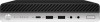
cable slot 9 5 DisplayPort monitor connectors (2) 10 USB SuperSpeed ports (2) Optional port USB SuperSpeed ports with optional keyboard power-on support (2) RJ-45 (network) jack Power connector Serial number location Each computer has a unique serial number and a product ID number that - HP EliteDesk 705 65W G4 | Hardware Reference Guide - Page 10
2 Setup Changing from desktop to tower orientation The computer can be used in a tower orientation with an optional tower stand that can be purchased from HP. 1. Remove/disengage any security devices that prohibit opening the computer. 2. Remove all removable media, such as a USB flash drive, from - HP EliteDesk 705 65W G4 | Hardware Reference Guide - Page 11
wall, swing arm, or other mounting fixture. NOTE: This apparatus is intended to be supported by UL or CSA Listed wall mount bracket. 1. If the computer is on a To attach the computer to other mounting fixtures, follow the instructions included with the mounting fixture to ensure that the computer is - HP EliteDesk 705 65W G4 | Hardware Reference Guide - Page 12
Installing a security lock You can attach a security cable lock to the rear of the computer. Use the key provided to attach and remove the lock. To install a padlock, slide the padlock loop out from the rear of the computer and install the padlock in the loop. NOTE: The cable lock and padlock are - HP EliteDesk 705 65W G4 | Hardware Reference Guide - Page 13
Connecting the power cord Connect one end of the power cord to the AC adapter (1) and the other end to a grounded AC outlet (2), and then connect the round end of the AC adapter to the power connector on the computer (3). Connecting the power cord 7 - HP EliteDesk 705 65W G4 | Hardware Reference Guide - Page 14
to upgrade and service. A Torx T15 or flat-bladed screwdriver is needed for some of the installation procedures described in this chapter. Warnings and cautions Before performing upgrades be sure to carefully read all of the applicable instructions, cautions, and warnings in this guide. WARNING! To - HP EliteDesk 705 65W G4 | Hardware Reference Guide - Page 15
Removing the computer access panel To access internal components, you must remove the access panel. 1. Remove/disengage any security devices that prohibit opening the computer. 2. Remove all removable media, such as a USB flash drive, from the computer. 3. Turn off the computer properly through the - HP EliteDesk 705 65W G4 | Hardware Reference Guide - Page 16
Replacing the computer access panel Place the access panel on the computer (1), and then slide it back (2). Then install the thumbscrew (3) to secure the panel in place. NOTE: Your computer model may look slightly different from the illustration in this section. Some models have vent holes on the - HP EliteDesk 705 65W G4 | Hardware Reference Guide - Page 17
properly if you install unsupported memory modules. Memory modules constructed with x8 and x16 DDR devices are supported; memory modules constructed with x4 SDRAM are not supported. HP offers upgrade memory for this computer and advises that the consumer purchase it to avoid compatibility issues - HP EliteDesk 705 65W G4 | Hardware Reference Guide - Page 18
Installing memory modules There are two memory module slots on the system board, with one slot per channel. The slots are labeled DIMM1 and DIMM3. The DIMM1 slot operates in memory channel B. The DIMM3 slot operates in memory channel A. Item 1 2 Description Memory module slot, Channel A Memory - HP EliteDesk 705 65W G4 | Hardware Reference Guide - Page 19
devices. 5. If the computer is on a stand, remove the computer from the stand and lay the computer down. 6. Remove the computer access panel. For instructions, see Removing the computer access panel on page 9. 7. Tilt the fan up using the front tab and leave it in the up position. Upgrading system - HP EliteDesk 705 65W G4 | Hardware Reference Guide - Page 20
8. Locate the memory module locations (1) and (2) on the system board. 9. To remove a memory module, press outward on the two latches on each side of the memory module (1), and then pull the memory module (2) out of the slot. 14 Chapter 3 Hardware upgrades - HP EliteDesk 705 65W G4 | Hardware Reference Guide - Page 21
match the notch on the module with the tab on the memory module slot. 11. Tilt the fan down. 12. Replace the access panel. For instructions, see Replacing the computer access panel on page 10. Upgrading system memory 15 - HP EliteDesk 705 65W G4 | Hardware Reference Guide - Page 22
source before opening the computer. 5. If the computer is on a stand, remove the computer from the stand. 6. Remove the computer access panel. For instructions, see Removing the computer access panel on page 9. 7. To remove the hard drive, rotate the hard drive latch up (1) to disengage the hard - HP EliteDesk 705 65W G4 | Hardware Reference Guide - Page 23
: See Removing a hard drive on page 16 for instructions on removing a hard drive. 1. If you are replacing a hard drive, transfer the four mounting screws from the old hard drive to the new hard drive. NOTE: Mounting screws can be purchased from HP. 2. If you are installing a hard drive rather than - HP EliteDesk 705 65W G4 | Hardware Reference Guide - Page 24
into the cage, and slide it forward (1). Then rotate the hard drive latch down (2) to engage the hard drive. 4. Replace the access panel. For instructions, see Replacing the computer access panel on page 10. 5. If the computer was on a stand, replace the stand. 6. Reconnect external devices, plug in - HP EliteDesk 705 65W G4 | Hardware Reference Guide - Page 25
a. Rotate the hard drive latch up (1) to disengage the hard drive from the cage. Then slide the drive toward the rear of the chassis until it stops, and then lift the hard drive up and out of the cage (2). b. Remove the hard drive cable clamp from the connector on the system board (1). Disconnect - HP EliteDesk 705 65W G4 | Hardware Reference Guide - Page 26
b. Remove the three screws (1) that secure the graphics processor to the chassis, and then lift the graphics processor (2) out of the chassis. 20 Chapter 3 Hardware upgrades - HP EliteDesk 705 65W G4 | Hardware Reference Guide - Page 27
8. Locate the M.2 SSD on the system board. 9. Remove the screw (1) securing the SSD to the system board, and then pull the SSD from the socket (2) on the system board. Replacing an M.2 PCIe solid state drive (SSD) 21 - HP EliteDesk 705 65W G4 | Hardware Reference Guide - Page 28
10. Slide the connector end of the SSD into the socket (1) on the system board, and then secure the SSD with the screw (2). 11. Replace the hard drive cage or the graphics processor, depending on your model. For models with a hard drive: a. Place the hard drive cage down into the chassis, and then - HP EliteDesk 705 65W G4 | Hardware Reference Guide - Page 29
b. Align the hard drive mounting screws with the slots on the hard drive cage, press the hard drive down into the cage, and slide it forward (1). Then rotate the hard drive latch down (2) to engage the hard drive. For models with a graphics processor: a. Place the graphics processor down into the - HP EliteDesk 705 65W G4 | Hardware Reference Guide - Page 30
the fan assembly with the four screws (2), and then connect the fan assembly cable (3) to the system board. 12. Replace the access panel. For instructions, see Replacing the computer access panel on page 10. 13. If the computer was on a stand, replace the stand. 14. Reconnect external devices, plug - HP EliteDesk 705 65W G4 | Hardware Reference Guide - Page 31
. 5. If the computer is on a stand, remove the computer from the stand and lay the computer down. 6. Remove the computer access panel. For instructions, see Removing the computer access panel on page 9. 7. To access the WLAN module, you must remove the hard drive cage or the graphics processor - HP EliteDesk 705 65W G4 | Hardware Reference Guide - Page 32
b. Remove the hard drive cable clamp from the connector on the system board (1). Disconnect the hard drive cable (2) from the system board using the pull tab on the cable, and then remove the two screws (3) that secure the hard drive cage to the chassis. Slide the hard drive cage back and lift it - HP EliteDesk 705 65W G4 | Hardware Reference Guide - Page 33
b. Remove the three screws (1) that secure the graphics processor to the chassis, and then lift the graphics processor (2) out of the chassis. 8. Locate the WLAN module on the system board. Replacing the WLAN module 27 - HP EliteDesk 705 65W G4 | Hardware Reference Guide - Page 34
9. Disconnect both antenna cables (1) from the WLAN module. Remove the screw (2) securing the WLAN module to the system board, and then grasp the WLAN module by the sides and pull it out of the socket (3). NOTE: You may need to use a small tool, such as a pair of tweezers or needle-nose pliers, to - HP EliteDesk 705 65W G4 | Hardware Reference Guide - Page 35
10. Insert the new WLAN module firmly into the socket (1) on the system board, and then secure the module to the system board using the screw (2) provided. Match the label on each antenna cable to the corresponding connector on the WLAN module and attach the antenna cables (3) to the connectors. - HP EliteDesk 705 65W G4 | Hardware Reference Guide - Page 36
b. Align the hard drive mounting screws with the slots on the hard drive cage, press the hard drive down into the cage, and slide it forward (1). Then rotate the hard drive latch down (2) to engage the hard drive. For models with a graphics processor: a. Place the graphics processor down into the - HP EliteDesk 705 65W G4 | Hardware Reference Guide - Page 37
. Secure the fan assembly with the four screws (2), and then connect the fan assembly cable (3) to the system board. 12. Replace the access panel. For instructions, see Replacing the computer access panel on page 10. 13. If the computer was on a stand, replace the stand. 14. Plug in the power cord - HP EliteDesk 705 65W G4 | Hardware Reference Guide - Page 38
. 5. If the computer is on a stand, remove the computer from the stand and lay the computer down. 6. Remove the computer access panel. For instructions, see Removing the computer access panel on page 9. 7. To access the WLAN module, you must remove the hard drive cage or the graphics processor - HP EliteDesk 705 65W G4 | Hardware Reference Guide - Page 39
b. Remove the hard drive cable clamp from the connector on the system board (1). Disconnect the hard drive cable (2) from the system board using the pull tab on the cable, and then remove the two screws (3) that secure the hard drive cage to the chassis. Slide the hard drive cage back and lift it - HP EliteDesk 705 65W G4 | Hardware Reference Guide - Page 40
processor (2) out of the chassis. 8. Locate the WLAN module on the system board. 9. Disconnect the internal antenna cables from the WLAN module. For instructions, see Replacing the WLAN module on page 25. 10. Locate both external antenna positions on the rear of the chassis. 34 Chapter 3 Hardware - HP EliteDesk 705 65W G4 | Hardware Reference Guide - Page 41
11. To view the knock-out feature on the left side of the rear panel, remove the antenna cover by pushing down on the antenna cover (1) and pulling it away from the panel (2). Disconnect the internal antenna (3) from the chassis and pull the internal antenna cable out of the chassis. Then insert a - HP EliteDesk 705 65W G4 | Hardware Reference Guide - Page 42
a. Place the hard drive cage down into the chassis, and then slide it forward (1). Install the two screws (2) that secure the hard drive cage to the chassis, and then connect the hard drive cable (3) to the system board. Secure the cable by attaching the hard drive cable clamp (4) to the system - HP EliteDesk 705 65W G4 | Hardware Reference Guide - Page 43
. Secure the fan assembly with the four screws (2), and then connect the fan assembly cable (3) to the system board. 15. Replace the access panel. For instructions, see Replacing the computer access panel on page 10. 16. If the computer was on a stand, replace the stand. 17. Plug in the power cord - HP EliteDesk 705 65W G4 | Hardware Reference Guide - Page 44
dispose of in fire or water. Replace the battery only with the HP spare designated for this product. IMPORTANT: Before replacing the battery, it stand and lay the computer down. 6. Remove the computer access panel. For instructions, see Removing the computer access panel on page 9. 7. To access the - HP EliteDesk 705 65W G4 | Hardware Reference Guide - Page 45
b. Remove the hard drive cable clamp from the connector on the system board (1). Disconnect the hard drive cable (2) from the system board using the pull tab on the cable, and then remove the two screws (3) that secure the hard drive cage to the chassis. Slide the hard drive cage back and lift it - HP EliteDesk 705 65W G4 | Hardware Reference Guide - Page 46
b. Remove the three screws (1) that secure the graphics processor to the chassis, and then lift the graphics processor (2) out of the chassis. 40 Chapter 3 Hardware upgrades - HP EliteDesk 705 65W G4 | Hardware Reference Guide - Page 47
8. Locate the battery and battery holder on the system board. NOTE: You may need to use a small tool, such as tweezers or needle-nose pliers, to remove and replace the battery. 9. Lift the battery out of the holder. 10. Slide the replacement battery into position, positive side up. The battery - HP EliteDesk 705 65W G4 | Hardware Reference Guide - Page 48
b. Align the hard drive mounting screws with the slots on the hard drive cage, press the hard drive down into the cage, and slide it forward (1). Then rotate the hard drive latch down (2) to engage the hard drive. For models with a graphics processor: a. Place the graphics processor down into the - HP EliteDesk 705 65W G4 | Hardware Reference Guide - Page 49
b. Place the fan assembly (1) on the graphics processor. Secure the fan assembly with the four screws (2), and then connect the fan assembly cable (3) to the system board. 12. Replace the computer access panel. 13. If the computer was on a stand, replace the stand. 14. Plug in the power cord and - HP EliteDesk 705 65W G4 | Hardware Reference Guide - Page 50
factory. If they do not work, remove and replace the batteries. If the mouse and keyboard are still not synchronized, follow this procedure to manually resynchronize the pair. 1. Connect the receiver to a USB port on the computer. If your computer only has USB SuperSpeed ports, connect the receiver - HP EliteDesk 705 65W G4 | Hardware Reference Guide - Page 51
3. Press the Connect button on the receiver for approximately five seconds. The status light on the receiver will flash for approximately 30 seconds after the Connect button is pressed. 4. While the status light on the receiver is flashing, press the Connect button on the underside of the keyboard - HP EliteDesk 705 65W G4 | Hardware Reference Guide - Page 52
5. Press the Connect button on the receiver for approximately five seconds. The status light on the receiver will flash for approximately 30 seconds after the Connect button is pressed. 6. While the status light on the receiver is flashing, press the Connect button on the underside of the mouse for - HP EliteDesk 705 65W G4 | Hardware Reference Guide - Page 53
work mat. If you do not have any of the suggested equipment for proper grounding, contact an HP authorized dealer, reseller, or service provider. NOTE: For more information on static electricity, contact an HP authorized dealer, reseller, or service provider. Preventing electrostatic damage 47 - HP EliteDesk 705 65W G4 | Hardware Reference Guide - Page 54
the computer by blocking any vents or air intakes. Do not place the keyboard, with the keyboard feet down, directly against the front of the desktop unit as this also restricts airflow. ● Never operate the computer with the access panel or any of the expansion card slot covers removed. ● Do not - HP EliteDesk 705 65W G4 | Hardware Reference Guide - Page 55
Shipping preparation Follow these suggestions when preparing to ship the computer: 1. Back up the hard drive files to an external storage device. Be sure that the backup media is not exposed to electrical or magnetic impulses while stored or in transit. NOTE: The hard drive locks automatically when - HP EliteDesk 705 65W G4 | Hardware Reference Guide - Page 56
designs, produces, and markets products and services that can be used by everyone, including people with disabilities, either on a stand-alone basis or with appropriate assistive devices. Supported assistive technologies HP products support a wide variety of operating system assistive technologies - HP EliteDesk 705 65W G4 | Hardware Reference Guide - Page 57
Index A access panel removal 9 replacement 10 accessibility 50 B battery installation 38 removal 38 C computer operating guidelines 48 E electrostatic discharge, preventing damage 47 external antenna installation 32 F front components 2 H hard drive installation 17 removal 16 I installation
-
 1
1 -
 2
2 -
 3
3 -
 4
4 -
 5
5 -
 6
6 -
 7
7 -
8
-
9
-
10
-
11
-
12
-
13
-
14
-
15
-
16
-
17
-
18
-
19
-
20
-
21
-
22
-
23
-
24
-
25
-
26
-
27
-
28
-
29
-
30
-
31
-
32
-
33
-
34
-
35
-
36
-
37
-
38
-
39
-
40
-
41
-
42
-
43
-
44
-
45
-
46
-
47
-
48
-
49
-
50
-
51
-
52
-
53
-
54
-
55
-
56
-
57
 |
 |

Hardware Reference Guide
HP EliteDesk 705 G4 Desktop Mini