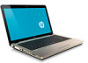
HP G62-300 HP G62 Notebook PC - Maintenance and Service Guide
HP G62-300 - Notebook PC Manual
 |
View all HP G62-300 manuals
Add to My Manuals
Save this manual to your list of manuals |
HP G62-300 manual content summary:
- HP G62-300 | HP G62 Notebook PC - Maintenance and Service Guide - Page 1
HP G62 Notebook PC Maintenance and Service Guide SUMMARY This guide is a troubleshooting reference used for maintaining and servicing the computer. It provides comprehensive information on identifying computer features, components, and spare parts; troubleshooting computer problems; and performing - HP G62-300 | HP G62 Notebook PC - Maintenance and Service Guide - Page 2
to change without notice. The only warranties for HP products and services are set forth in the express warranty statements accompanying such products and services. Nothing herein should be construed as constituting an additional warranty. HP shall not be liable for technical or editorial errors - HP G62-300 | HP G62 Notebook PC - Maintenance and Service Guide - Page 3
Safety warning notice WARNING! To reduce the possibility of heat-related injuries or of overheating the computer, do not place the computer directly on your lap or obstruct the computer air vents. Use the computer only on a hard, flat surface. Do not allow another hard surface, such as an adjoining - HP G62-300 | HP G62 Notebook PC - Maintenance and Service Guide - Page 4
iv Safety warning notice - HP G62-300 | HP G62 Notebook PC - Maintenance and Service Guide - Page 5
components on page 17, Mass storage devices on page 26, Sequential part number listing on page 29, Hard drive on page 42. ● Added newly supported memory modules to spare parts listings in the following locations: Computer major components on page 17, Mass storage devices on page 26, Sequential part - HP G62-300 | HP G62 Notebook PC - Maintenance and Service Guide - Page 6
vi MSG revision history - HP G62-300 | HP G62 Notebook PC - Maintenance and Service Guide - Page 7
Mass storage devices ...26 Miscellaneous parts ...28 Sequential part number listing ...29 4 Removal and replacement procedures ...34 Preliminary replacement requirements 34 Tools required ...34 Service considerations ...34 Plastic parts ...34 Cables and connectors 35 Drive handling 35 Grounding - HP G62-300 | HP G62 Notebook PC - Maintenance and Service Guide - Page 8
37 Workstation guidelines 37 Equipment guidelines 38 Component replacement procedures 39 Serial number ...39 Computer feet ...40 Battery ...41 Hard drive ...42 Optical drive ...45 WLAN module ...47 Memory module ...50 ...51 RTC battery ...51 Keyboard ...53 Top cover ...56 Speaker assembly ...59 - HP G62-300 | HP G62 Notebook PC - Maintenance and Service Guide - Page 9
Using Computer Setup ...88 Navigating and selecting in Computer Setup 88 Restoring factory settings in Computer Setup 89 Computer Setup menus ...90 File menu ...90 Security menu 91 Diagnostics menu 91 System Configuration menu 92 6 Specifications ...94 Computer specifications ...94 39.6-cm (15 - HP G62-300 | HP G62 Notebook PC - Maintenance and Service Guide - Page 10
10 Recycling ...114 Battery ...114 Display ...114 Index ...121 x - HP G62-300 | HP G62 Notebook PC - Maintenance and Service Guide - Page 11
Chipset Graphics Panel Memory Description Compaq Presario CQ62 Notebook PC HP G62 Notebook PC Chipset Intel HD Graphics Media Accelerator HP G62 UMA ATI Mobility Radeon™ HD5470 with 512 MB dedicated video memory ATI Mobility Radeon HD 545v with 512 MB for vision label mapping Support - HP G62-300 | HP G62 Notebook PC - Maintenance and Service Guide - Page 12
drive Customer accessible Supports the following drives: ● 750 GB, 5400 rpm ● 640 GB, 5400 rpm ● 500 GB, 5400 rpm ● 500 GB, 7200 rpm ● 320 GB, 5400 rpm ● 320 GB, 7200 antennas built into display assembly Support for no-WLAN option HP G62 UMA √ √ √ √ √ √ √ √ √ HP G62 Discrete √ √ √ √ - HP G62-300 | HP G62 Notebook PC - Maintenance and Service Guide - Page 13
, 55 Wh battery 6-cell, 2.8-Ah, 62 Wh battery 9-cell, 2.8-Ah, 93 Wh battery 65-W AC adapter with localized cable plug support 90-W AC adapter with localized cable plug support Kensington Security Lock Preinstalled: Windows 7® Home Premium (32 & 64 bit) Windows 7 Home Basic (32 & 64 bit) HP G62 UMA - HP G62-300 | HP G62 Notebook PC - Maintenance and Service Guide - Page 14
Category Serviceability Description Free DOS End-user replaceable parts: AC adapter Battery (system) Hard drive Memory module Optical drive Mini-card devices HP G62 UMA √ HP G62 Discrete √ √ √ √ √ √ √ √ √ √ √ √ √ 4 Chapter 1 Product description - HP G62-300 | HP G62 Notebook PC - Maintenance and Service Guide - Page 15
2 External component identification Identifying the hardware Components included with the computer might vary by region and model. The illustrations in this chapter identify the standard features on most computer models. To see a list of hardware installed in the computer: 1. Select Start > My - HP G62-300 | HP G62 Notebook PC - Maintenance and Service Guide - Page 16
Top components TouchPad Component (1) TouchPad light (2) TouchPad zone (3) Left TouchPad button (4) Right TouchPad button *This table describes factory settings. Description Off-Touchpad is on. Amber-Touchpad is off. Moves the pointer and selects or activates items on the screen. Press - HP G62-300 | HP G62 Notebook PC - Maintenance and Service Guide - Page 17
Lights Component (1) TouchPad light (2) Caps lock light (3) Power light (4) Wireless light Description ● Off-TouchPad is enabled. ● Amber-TouchPad is disabled. On-Caps lock is on ● On-The computer is on. ● Flashing-The computer is in Sleep. ● Off-The computer is off or in Hibernation. ● - HP G62-300 | HP G62 Notebook PC - Maintenance and Service Guide - Page 18
and Security > Power Options. (2) Speakers grill Two integrated speakers produce sound. *This table describes factory settings. For information about changing factory settings, see the user guides located in Help and Support. 8 Chapter 2 External component identification - HP G62-300 | HP G62 Notebook PC - Maintenance and Service Guide - Page 19
Keys Component (1) esc key (2) Send e-mail key (3) Media application key (4) Web browser key (5) Print key (6) Calculator key (7) fn key (8) Windows logo key (9) Windows applications key (10) Action keys Description Displays system information when pressed in combination with - HP G62-300 | HP G62 Notebook PC - Maintenance and Service Guide - Page 20
Display Component (1) Wireless antenna (2) (2) Internal microphone (3) Integrated webcam (select models only) (4) Webcam light (select models only) Description Sends and receives signals from one or more wireless devices. Records sound. Records audio and video and captures still - HP G62-300 | HP G62 Notebook PC - Maintenance and Service Guide - Page 21
Right-side components Component (1) Optical drive (2) USB port (3) RJ-11 (modem) jack (select models only) (4) AC adapter light (5) Power connector (6) Security cable slot Description Reads and writes to optical discs. Connects an optional USB device. Connects a modem cable. ● Flashing - HP G62-300 | HP G62 Notebook PC - Maintenance and Service Guide - Page 22
microphone, or monaural microphone. Produces sound when connected to optional powered stereo speakers, headphones, earbuds, a headset, or television audio. Supports the following optional digital card formats: ● Memory Stick (MS) ● Memory Stick Pro (MSP) ● MultiMediaCard (MMC) ● Secure Digital (SD - HP G62-300 | HP G62 Notebook PC - Maintenance and Service Guide - Page 23
bay Description Holds the battery. Enable airflow to battery from the battery bay. Contains two memory module slots and, on select models, the wireless LAN (WLAN) device. CAUTION: To prevent an unresponsive system, replace your country or region. If you replace the module and then receive a warning - HP G62-300 | HP G62 Notebook PC - Maintenance and Service Guide - Page 24
visible from the outside of the computer. NOTE: For optimal transmission, keep the areas immediately around the antennas free from obstructions. To review the wireless regulatory notices, see to the section of the Regulatory, Safety and Environmental Notices that applies to your country or region - HP G62-300 | HP G62 Notebook PC - Maintenance and Service Guide - Page 25
Additional hardware components Component (1) Power cord* (2) AC adapter (3) Battery* *Power cords vary in appearance by country or region. Description Connects an AC adapter to an AC outlet. Converts AC power to DC power. Powers - HP G62-300 | HP G62 Notebook PC - Maintenance and Service Guide - Page 26
provide the computer serial number and model number located in the battery bay of the computer. Component (1) Product name (2) Serial information about the product's hardware components. The part number helps a service technician to determine what components and parts are needed. The duration - HP G62-300 | HP G62 Notebook PC - Maintenance and Service Guide - Page 27
Computer major components Computer major components 17 - HP G62-300 | HP G62 Notebook PC - Maintenance and Service Guide - Page 28
models 605906-001 605907-001 ● HP G62 white computer models 605908-001 ● HP G62 matte black computer models 608444-001 ● HP G62 red computer models ● HP G62 blue computer models 615423-001 615424-001 Power button board 606008-001 Keyboard (includes keyboard cable) for use in: ● Adriatics - HP G62-300 | HP G62 Notebook PC - Maintenance and Service Guide - Page 29
only) (for model 1.0 only) RTC battery (includes mounting adhesive) System board (includes replacement thermal material) for use in: ● ● 500 GB, 5400 rpm (for model 1.1 only) ● 500 GB, 7200 rpm ● 320 GB, 5400 rpm (for model 1.1 only) ● 320 GB, 7200 rpm ● 250 GB, 5400 rpm (for model 1.1 only) ● 250 GB - HP G62-300 | HP G62 Notebook PC - Maintenance and Service Guide - Page 30
Item (14) Description Spare part number ● Intel Arrandale i5-540M Processor (2.53 GHz, 3 MB total L3 cache, 1066 MHz)- Dual core 35 W 594188-001 ● Intel Arrandale i3-330 Processor (2.13 GHz, 3 MB L3 cache, 1066 MHz)-Dual Core 35 W (for model 1.0 only) 597622-001 ● Intel Arrandale i3-350 - HP G62-300 | HP G62 Notebook PC - Maintenance and Service Guide - Page 31
Item (15) Description Spare part number ● Intel WiFi Link 5100 802.11/b/g/n WLAN module for use in Afghanistan, Albania, 593530-001 Algeria, Andorra, Angola, Antigua and Barbuda, Argentina, Armenia, Aruba, Australia, Austria, Azerbaijan, the Bahamas, Bahrain, Bangladesh, Barbados, Belarus, - HP G62-300 | HP G62 Notebook PC - Maintenance and Service Guide - Page 32
Item (16) (17) (18) (19) (20) (21) (21) (23) Description ● White computer models ● Red computer models ● Blue computer models Battery ● 6-cell Li-lon, 2.20 Ah, 47 Wh ● 6-cell Li-lon, 2.55 Ah, 55 Wh Power connector (includes cable) USB board RJ-11 connector included in - HP G62-300 | HP G62 Notebook PC - Maintenance and Service Guide - Page 33
Display assembly components Item (1) (2) (3) (4) (5) Description Display bezel Display bracket (with hinges) 39.6-cm (15.6-in) high definition, Brightview, display panel (includes display panel cable) Microphone(includes calbe) Webcam module Webcam module cable Spare part number 605913-001 605915 - HP G62-300 | HP G62 Notebook PC - Maintenance and Service Guide - Page 34
Item (6) (7) (8) Description Spare part number Wireless antenna (includes wireless antenna transceivers and cable) 606016-001 Display back cover (includes logo) for use with: ● Matte black computer models 608445-001 ● Biscotti computer models ● Silver computer models ● White computer models - HP G62-300 | HP G62 Notebook PC - Maintenance and Service Guide - Page 35
Plastics Kit Item Description Plastics kit (1) Hard drive bay cover (includes captive screws) (2) Wireless/memory module mini-card compartment cover (includes captive screw) Spare part number 606006-001 Plastics Kit 25 - HP G62-300 | HP G62 Notebook PC - Maintenance and Service Guide - Page 36
Mass storage devices Item (1) (2) Description Spare part number Optical drive (12.7 mm, SATA, fixed, includes bezel and bracket) DVD±RW and CD-RW SuperMulti Double-Layer Combo Drive with LightScribe for use with: ● Matte black computer models 605920-001 ● Biscotti computer models 610558-001 - HP G62-300 | HP G62 Notebook PC - Maintenance and Service Guide - Page 37
Item Description ● 640 GB, 5400 rpm ● 500 GB, 5400 rpm (for model 1.1 only) ● 500 GB, 7200 rpm ● 320 GB, 5400 rpm (for model 1.1 only) ● 320 GB, 7200 rpm ● 250 GB, 5400 rpm (for model 1.1 only) ● 250 GB, 7200 rpm ● 160 GB, 7200 rpm Hard drive hardware kit (not illustrated, includes - HP G62-300 | HP G62 Notebook PC - Maintenance and Service Guide - Page 38
number AC adapters ● 65-W AC adapter 609939-001 ● 90-W AC adapter 609940-001 Power cord, AC, 3 wire, black, 1.83-m (for use with both HP G62 and Presario CQ 62 computer models) for use in: ● Denmark 490371-081 ● Europe 490371-021 ● Israel 490371-BB1 ● Italy 490371-061 ● North America - HP G62-300 | HP G62 Notebook PC - Maintenance and Service Guide - Page 39
HP G62 computer models Power cord for use in Italy with HP G62 computer models Power cord for use in Denmark with HP G62 computer models Power cord for use in Switzerland with HP G62 Realtek RTL8191SE 802.11b/g/n 1x1 WiFi Adapter Battery, 6-cell, 2.20 Ah, 47 Wh Battery, 6-cell, 2.55 Ah, 55 Wh - HP G62-300 | HP G62 Notebook PC - Maintenance and Service Guide - Page 40
.6-in) HD, light-emitting diode display assembly for HP G62 white computer models Display back cover for use with HP G62 biscotti computer models Display back cover for use with HP G62 silver computer models Display back cover for use with HP G62 white computer models Display bezel Display hinge kit - HP G62-300 | HP G62 Notebook PC - Maintenance and Service Guide - Page 41
thermal material) for use with UMA systems Fan/heat sink assembly (includes replacement thermal material) for use with discrete systems RTC battery Wireless antenna kit (includes wireless antenna transceivers and cable) Display hinge covers Base enclosure with HDMI card reader for matte black - HP G62-300 | HP G62 Notebook PC - Maintenance and Service Guide - Page 42
HD 5470/1 G discrete system board with card reader 39.6-cm (15.6-in) HD, light-emitting diode display assembly for HP G62 matte black computer models Display back cover for use with HP G62 matte black computer models Power connector (includes cable) 65-W AC adapter 90-W AC adapter DVD±RW and CD-RW - HP G62-300 | HP G62 Notebook PC - Maintenance and Service Guide - Page 43
SuperMulti Double-Layer Drive for use with blue computer models 750 GB, 5400 rpm hard drive 250 GB, 5400 rpm hard drive (for model 1.1 only) 320 GB, 5400 rpm hard drive (for model 1.1 only) Intel Arrandale i3-380 Processor (2.53 GHz, 3 MB L3 cache, 1066 MHz)-Dual Core 35 W (for model - HP G62-300 | HP G62 Notebook PC - Maintenance and Service Guide - Page 44
replacement procedures: ● Flat-bladed screwdriver ● Magnetic screwdriver ● Phillips P0 and P1 screwdrivers Service considerations Before disassembly or assembly procedures, review and adhere to all service designated in the maintenance instructions. 34 Chapter 4 Removal and replacement procedures - HP G62-300 | HP G62 Notebook PC - Maintenance and Service Guide - Page 45
Cables and connectors CAUTION: When servicing the computer, be sure that cables are placed in are routed in such a way that they cannot be caught or snagged by parts being removed or replaced. Handle flex cables with extreme care; these cables tear easily. Drive handling CAUTION: Drives are fragile - HP G62-300 | HP G62 Notebook PC - Maintenance and Service Guide - Page 46
V 4,000 V 14,500 V 5,000 V 26,500 V 20,000 V 21,000 V 11,000 V 55% 7,500 V 3,000 V 400 V 400 V 2,000 V 3,500 V 7,000 V 5,000 V 36 Chapter 4 Removal and replacement procedures - HP G62-300 | HP G62 Notebook PC - Maintenance and Service Guide - Page 47
grounded work surface and use properly grounded tools and equipment. ● Use conductive field service tools, such as cutters, screwdrivers, and vacuums. ● When fixtures must directly contact signals before inserting or removing connectors or test equipment. Preliminary replacement requirements 37 - HP G62-300 | HP G62 Notebook PC - Maintenance and Service Guide - Page 48
resistance ● Static-dissipative tables or floor mats with hard ties to the ground ● Field service kits ● Static awareness labels ● Material-handling packages ● Nonconductive plastic bags, tubes, or Voltage protection level 1,500 V 7,500 V 5,000 V 38 Chapter 4 Removal and replacement procedures - HP G62-300 | HP G62 Notebook PC - Maintenance and Service Guide - Page 49
, replaced, or loosened when servicing the computer. Make special note of each screw size and location during removal and replacement. Serial number The serial number label, located in the battery bay of the computer, provides important information that you may need when contacting technical support - HP G62-300 | HP G62 Notebook PC - Maintenance and Service Guide - Page 50
Computer feet Description Rubber Feet Kit Spare part number 606012-001 The computer feet are adhesive-backed rubber pads. The feet attach to the base enclosure in the locations illustrated below. 40 Chapter 4 Removal and replacement procedures - HP G62-300 | HP G62 Notebook PC - Maintenance and Service Guide - Page 51
the battery (2) upward and lift it out of the computer (3). To insert the battery, insert the rear edge of the battery into the battery bay and pivot the front edge downward until the battery is seated. The battery release latch automatically locks the battery into place. Component replacement - HP G62-300 | HP G62 Notebook PC - Maintenance and Service Guide - Page 52
(for models 1.1 only) 500 GB, 7200 rpm 0 GB, 5400 rpm (for models 1.1 only) 320 GB, 7200 rpm 0 GB, 5400 rpm (for models 1.1 only) 250 GB, 7200 rpm 160 then disconnecting the AC adapter from the computer. 4. Remove the battery (see Battery on page 41). Remove the hard drive: 1. Position the computer - HP G62-300 | HP G62 Notebook PC - Maintenance and Service Guide - Page 53
the hard drive bracket to move the hard drive to the right (2) bracket to lift the hard drive out (3) of the hard drive bay. 6. To replace the hard drive bracket, remove the four Phillips PM3.0×4.0 screws (1) that secure the hard drive bracket to the hard drive Component - HP G62-300 | HP G62 Notebook PC - Maintenance and Service Guide - Page 54
7. Grasp the two attached Mylar tabs and pull the bracket straight up to remove it from the hard drive (2). Reverse this procedure to install the hard drive. 44 Chapter 4 Removal and replacement procedures - HP G62-300 | HP G62 Notebook PC - Maintenance and Service Guide - Page 55
(see Battery on page 41). 5. Remove the hard drive (see Hard drive on page 42). Remove the optical drive: 1. Position the computer upside down with the front toward you. 2. Insert a thin tool, such as a screw driver (1), into the release access slot in the hard drive bay. Component replacement - HP G62-300 | HP G62 Notebook PC - Maintenance and Service Guide - Page 56
3. Grasp the bezel and slide the optical drive out of the computer (2). 4. To replace the optical drive bracket, position the optical drive with the optical drive bracket toward you. the above procedure to reassemble and install the optical drive. 46 Chapter 4 Removal and replacement procedures - HP G62-300 | HP G62 Notebook PC - Maintenance and Service Guide - Page 57
(see Battery on page 41). Remove the WLAN module: 1. Turn the computer upside down with the front toward you. 2. Loosen the two Phillips PM2.5×6.0 captive screws (1) that secure the mini-card compartment cover. 3. Lift the back side of the memory module cover (2) . Component replacement procedures - HP G62-300 | HP G62 Notebook PC - Maintenance and Service Guide - Page 58
(3) that secures the WLAN module to the computer. (The edge of the module opposite the slot rises away from the computer.) 48 Chapter 4 Removal and replacement procedures - HP G62-300 | HP G62 Notebook PC - Maintenance and Service Guide - Page 59
regulates wireless devices in your country or region. If you replace the module and then receive a warning message, remove the module to restore computer functionality, and then contact technical support through Help and Support. NOTE: WLAN modules are designed with a notch (5) to prevent incorrect - HP G62-300 | HP G62 Notebook PC - Maintenance and Service Guide - Page 60
cord from the AC outlet and then disconnecting the AC adapter from the computer. 4. Remove the battery (see Battery on page 41). Remove the memory module: 1. Turn the computer upside down with the front toward the slot rises away from the computer.) 50 Chapter 4 Removal and replacement procedures - HP G62-300 | HP G62 Notebook PC - Maintenance and Service Guide - Page 61
Remove the battery (see Battery on page 41). Remove the RTC battery: 1. Unplug the RTC battery from the system board (1). 2. Use a sharp, non-conductive, tool to release the RTC battery from the adhesive material that secures the RTC battery to the system board.. Component replacement procedures 51 - HP G62-300 | HP G62 Notebook PC - Maintenance and Service Guide - Page 62
3. Lift the battery (2) out of the computer. Reverse this procedure to install the RTC battery. 52 Chapter 4 Removal and replacement procedures - HP G62-300 | HP G62 Notebook PC - Maintenance and Service Guide - Page 63
4. Remove the battery (see Battery on page 41). 5. Remove the hard drive (see Hard drive on page 42). 6. Remove the WLAN/Memory Module compartment cover (see WLAN module on page 47). Remove the keyboard: 1. Turn the computer upside down with the front toward you. Component replacement procedures 53 - HP G62-300 | HP G62 Notebook PC - Maintenance and Service Guide - Page 64
you. 4. Open the computer as far as possible. 5. Release the tabs along the left (1) and right (2) edges of the keyboard using a thin flat-bladed screwdriver. 6. Lift the rear edge of the keyboard (3), and set the keyboard back towards the display (4). 54 Chapter 4 Removal and replacement procedures - HP G62-300 | HP G62 Notebook PC - Maintenance and Service Guide - Page 65
7. Release the zero insertion force (ZIF) connector (1) to which the keyboard cable is attached and disconnect the keyboard cable (2) from the system board. 8. Remove the keyboard. Reverse this procedure to install the keyboard. Component replacement procedures 55 - HP G62-300 | HP G62 Notebook PC - Maintenance and Service Guide - Page 66
AC adapter from the computer. 4. Remove the following components: a. Battery (see Battery on page 41). b. Hard drive (See Hard drive on page Keyboard (see Keyboard on page 53). Remove the switch cover: 1. Turn the computer upside down with the front toward you. 56 Chapter 4 Removal and replacement - HP G62-300 | HP G62 Notebook PC - Maintenance and Service Guide - Page 67
2. Remove four Phillips PM2.5x3 screws in the battery bay, and remove nine Phillips PM2.5x6.5 screws on the base enclosure. The top cover screws are identified far as possible. 5. Remove the three Phillips PM2.5×6.0 screw that secures the top cover to the computer. Component replacement procedures 57 - HP G62-300 | HP G62 Notebook PC - Maintenance and Service Guide - Page 68
to the top cover and is included with the top cover spare part. Reverse this procedure to install the switch cover. 58 Chapter 4 Removal and replacement procedures - HP G62-300 | HP G62 Notebook PC - Maintenance and Service Guide - Page 69
Keyboard on page 53) d. Top cover (see Top cover on page 56) Remove the speaker assembly: 1. Turn the top cover upside down. 2. Remove the three Phillips PM2.5×3.0 screws (1) that secure the speaker assembly to the top cover. 3. Lift up and remove the speakers (2). Component replacement procedures - HP G62-300 | HP G62 Notebook PC - Maintenance and Service Guide - Page 70
Reverse this procedure to install the speaker assembly. 60 Chapter 4 Removal and replacement procedures - HP G62-300 | HP G62 Notebook PC - Maintenance and Service Guide - Page 71
(see Battery on page 41). 5. Remove the following components: a. Hard drive (see Hard drive on page 42) b. Optical drive (see Optical drive on page 45) c. Keyboard (see Keyboard on page 53) d. Top cover (see this procedure to install the power button board. Component replacement procedures 61 - HP G62-300 | HP G62 Notebook PC - Maintenance and Service Guide - Page 72
(see Battery on page 41). 5. Remove the following components: a. Hard drive (see Hard drive on page 42) b. Optical drive (see Optical drive on page 45) c. Keyboard (see Keyboard on page 53) d. Top cover (see Top install the TouchPad button board. 62 Chapter 4 Removal and replacement procedures - HP G62-300 | HP G62 Notebook PC - Maintenance and Service Guide - Page 73
(see Battery on page 41). 5. Remove the following components: a. Hard drive (see Hard drive on page 42) b. Optical drive (see Optical drive on page 45) c. Keyboard (see Keyboard on page 53) d. Top cover (see Top module (2) to disconnect it from the system board. Component replacement procedures 63 - HP G62-300 | HP G62 Notebook PC - Maintenance and Service Guide - Page 74
Reverse the above procedure to install the modem module, and be sure that the connector on the bottom of the modem module connects firmly into the system board. 64 Chapter 4 Removal and replacement procedures - HP G62-300 | HP G62 Notebook PC - Maintenance and Service Guide - Page 75
(see Battery on page 41). 5. Remove the following components: a. Hard drive (see Hard drive on page 42) b. Optical drive (see Optical drive on page 45) c. Keyboard (see Keyboard on page 53) d. Top cover (see Top the cable kit using spare part number 606009-001 Component replacement procedures 65 - HP G62-300 | HP G62 Notebook PC - Maintenance and Service Guide - Page 76
Reverse this procedure to install the USB board. 66 Chapter 4 Removal and replacement procedures - HP G62-300 | HP G62 Notebook PC - Maintenance and Service Guide - Page 77
(see Battery on page 41). 5. Remove the following components: a. Hard drive (see Hard drive on page 42) b. Optical drive (see Optical drive on page 45) c. Keyboard (see Keyboard on page 53) d. Top enclosure. Reverse this procedure to install the power connector. Component replacement procedures 67 - HP G62-300 | HP G62 Notebook PC - Maintenance and Service Guide - Page 78
Battery on page 41). 5. Disconnect the wireless antenna cables from the WLAN module (see WLAN module on page 47). 6. Remove the following components: a. Optical drive (see Optical drive on page 45) b. Keyboard (see Keyboard to the display hinge (4). 68 Chapter 4 Removal and replacement procedures - HP G62-300 | HP G62 Notebook PC - Maintenance and Service Guide - Page 79
that attach it to the system board. CAUTION: Support the display assembly when removing the display screws in the following steps. Failure to support the display assembly can result in damage to the it. Reverse this procedure to install the display assembly. Component replacement procedures 69 - HP G62-300 | HP G62 Notebook PC - Maintenance and Service Guide - Page 80
until the bezel disengages from the display back cover. 10. Remove the display bezel (4). Reverse this procedure to install the display bezel. 11. To replace the webcam module (select models only), lift the webcam module as far from the display enclosure as the webcam module cable allows. 70 Chapter - HP G62-300 | HP G62 Notebook PC - Maintenance and Service Guide - Page 81
the webcam module (2). The webcam module is available using spare part number 606001-001. Reverse this procedure to install the webcam module. 13. To replace the display hinge covers, remove the two Phillips PM2.5×6.0 screws (1) that secure each hinge to the display enclosure. 14. Remove the display - HP G62-300 | HP G62 Notebook PC - Maintenance and Service Guide - Page 82
enclosure. The display panel is available using the spare part number 606003-001. Reverse this procedure to install the display panel. 17. To replace the display panel brackets, remove the two Phillips PM2.0×3.0 screws (1) that secure each bracket to the display panel. 18. Remove the display panel - HP G62-300 | HP G62 Notebook PC - Maintenance and Service Guide - Page 83
20. Lift up to remove the antenna transceivers (3). The wireless antenna transceivers with cable is available using spare part number 606016-001.. Reverse this procedure to install the display wireless antenna transceivers. Component replacement procedures 73 - HP G62-300 | HP G62 Notebook PC - Maintenance and Service Guide - Page 84
from the computer. 4. Remove the battery (see Battery on page 41). 5. Remove the Keyboard (see Keyboard on page 53) f. Top cover (see Top cover on page 56) g. Modem module (see Modem module on page 63) h. Display assembly (see Display assembly on page 68) 74 Chapter 4 Removal and replacement - HP G62-300 | HP G62 Notebook PC - Maintenance and Service Guide - Page 85
board. 4. Lift the system board (3), and pull it away from the base enclosure at an angle. Reverse this procedure to install the system board. Component replacement procedures 75 - HP G62-300 | HP G62 Notebook PC - Maintenance and Service Guide - Page 86
the system board, be sure that the following components are removed from the defective system board and installed on the replacement system board: ● Fan/heat sink assembly (see Fan/heat sink assembly on page 77) ● Processor (see Processor on page 81) Reverse the preceding procedure to - HP G62-300 | HP G62 Notebook PC - Maintenance and Service Guide - Page 87
graphics subsystem memory Fan/heat sink assembly (includes replacement thermal material) for use only with computer models Battery on page 41). 5. Remove the following components: a. Hard drive (see Hard drive on page 42) b. Optical drive (see Optical drive on page 45) c. Keyboard (see Keyboard - HP G62-300 | HP G62 Notebook PC - Maintenance and Service Guide - Page 88
computer models equipped with graphics subsystems having discrete memory. 1. Turn the system board right-side up, with the front toward you. 78 Chapter 4 Removal and replacement procedures - HP G62-300 | HP G62 Notebook PC - Maintenance and Service Guide - Page 89
/heat sink assembly is removed. Thermal pads and thermal paste must be installed on all surfaces before the fan/heat sink assembly is reinstalled. Component replacement procedures 79 - HP G62-300 | HP G62 Notebook PC - Maintenance and Service Guide - Page 90
fan/heat sink assembly is reinstalled. The following illustration shows the locations for thermal material on systems with discrete graphics subsystems. 80 Chapter 4 Removal and replacement procedures - HP G62-300 | HP G62 Notebook PC - Maintenance and Service Guide - Page 91
computer. 4. Remove the battery (see Battery on page 41). 5. Remove the following components: a. Hard drive (see Hard drive on page 42) b. Optical drive (see Optical drive on page 45) c. Keyboard (see Keyboard on page 53) d. Top cover (see Top cover on page 56) Component replacement procedures 81 - HP G62-300 | HP G62 Notebook PC - Maintenance and Service Guide - Page 92
with the triangle icon (4) embossed on the processor socket when you install the processor. Reverse this procedure to install the processor. 82 Chapter 4 Removal and replacement procedures - HP G62-300 | HP G62 Notebook PC - Maintenance and Service Guide - Page 93
5 Setup Utility Computer Setup in Windows 7 To view the drives installed on the computer, select Start > Computer. On models with a secondary hard drive (drive D), the optical drive becomes drive E. The next drive added to the system, such as a new USB drive, is assigned the next available drive - HP G62-300 | HP G62 Notebook PC - Maintenance and Service Guide - Page 94
the enter key. Changes goes into effect immediately. Navigating and selecting in Setup Utility Because Setup Utility is not Windows based, it does not support the TouchPad. Navigation and selection are by keystroke. ● To choose a menu or a menu item, use the arrow keys. ● To choose an item in a list - HP G62-300 | HP G62 Notebook PC - Maintenance and Service Guide - Page 95
Restoring default settings in Setup Utility The following procedure explains how to restore Setup Utility default settings. If Setup Utility is not already running, begin at step 1. If Setup Utility is already running, begin at step 2. 1. Open Setup Utility by turning on or restarting the computer. - HP G62-300 | HP G62 Notebook PC - Maintenance and Service Guide - Page 96
computer restarts in Windows. Setup Utility menus The menu tables in this section provide an overview of Setup Utility options. NOTE: Some of the Setup Utility menu items listed in this chapter might not be supported by the computer. Main menu Select System information To do this ● View and change - HP G62-300 | HP G62 Notebook PC - Maintenance and Service Guide - Page 97
System Configuration menu Select Language Support Button Sound (select models only) Virtualization Technology ( ―Enable/disable boot from the internal network adapter. ● Boot Order―Set the boot order for: ◦ Notebook Hard Drive ◦ Internal CD/DVD ROM Drive ◦ USB Diskette on Key/USB Hard Disk ◦ USB - HP G62-300 | HP G62 Notebook PC - Maintenance and Service Guide - Page 98
guide might not be supported by the computer. NOTE: Pointing devices are not supported in Computer Setup. Use the keyboard to navigate and make selections. NOTE: An external keyboard select File > Ignore Changes And Exit. Then follow the instructions on the screen. ● To save your preferences and exit - HP G62-300 | HP G62 Notebook PC - Maintenance and Service Guide - Page 99
f10 key. 4. To save your preferences and exit Computer Setup, use the arrow keys to select File > Save Changes And Exit. Then follow the instructions on the screen. Your preferences go into effect when the computer restarts. NOTE: Your password settings and security settings are not changed when you - HP G62-300 | HP G62 Notebook PC - Maintenance and Service Guide - Page 100
Computer Setup menus The menu tables in this section provide an overview of Computer Setup options. NOTE: Some of the Computer Setup menu items listed in this chapter might not be supported by the computer. File menu Select System information Restore Defaults Ignore Changes And Exit Save Changes - HP G62-300 | HP G62 Notebook PC - Maintenance and Service Guide - Page 101
Security menu NOTE: Some of the menu items listed in this section might not be supported by the computer. Select Setup Password Power-On Password Password Options DriveLock Passwords System IDs Disk Sanitizer To do this Enter, change, or delete a setup - HP G62-300 | HP G62 Notebook PC - Maintenance and Service Guide - Page 102
2nd boot device-USB floppy ◦ 3rd boot device-USB SuperDisk ◦ 4th boot device-Notebook hard drive ◦ 5th boot device-USB hard disk ◦ 6th boot device-Network controller Enable/disable USB legacy support. When enabled, USB legacy support allows the following: ◦ Use of a USB keyboard in Computer Setup - HP G62-300 | HP G62 Notebook PC - Maintenance and Service Guide - Page 103
Select Built-in device options Port options To do this ● Enable/disable embedded WLAN Device Radio. ● Enable/disable embedded Bluetooth Device Radio. ● Enable/disable Network Interface Controller (NIC) ● Enable/disable LAN/WLAN Switching. ● Enable/disable Wake on LAN. ● Enable/disable the - HP G62-300 | HP G62 Notebook PC - Maintenance and Service Guide - Page 104
6 Specifications Computer specifications Dimensions Depth Width Height (front to rear) Weight (lowest weight configuration) Input power Operating voltage Operating current Temperature Operating (not writing to optical disc) 24.7 cm (9.7 in) 37.4 cm (14.7 in) 3.2 to 3.7 cm (1.3 to 1.4 in) < 2.25 - HP G62-300 | HP G62 Notebook PC - Maintenance and Service Guide - Page 105
Backlight Character display Total power consumption Viewing angle 21.0 cm (8.27 in) 35.9 cm (14.1 in) 39.6 cm (15.6) Up to 16.8 million 300:1 (typical) 200 nits (typical) 0.259 × 0.259 mm 1280 × 800; HD: 1366 × 768 RGB vertical stripe LED 80 × 25 4.0 W ±40° horizontal, +120/-40° vertical - HP G62-300 | HP G62 Notebook PC - Maintenance and Service Guide - Page 106
Hard drive specifications 640 GB* 500 GB* 320 GB* 250 GB* 160 GB* Dimensions Height 9.5 mm 9.5 mm 9.5 mm 9.5 mm 9.5 mm Width drive specifications may differ slightly. NOTE: Certain restrictions and exclusions apply. Contact technical support for details. 96 Chapter 6 Specifications - HP G62-300 | HP G62 Notebook PC - Maintenance and Service Guide - Page 107
DVD±RW and CD-RW SuperMulti Double-Layer Combo Drive with LightScribe specifications Applicable disc Read Write Random access time DVD CD Cache buffer Data transfer rate 24X CD-ROM 8X DVD-ROM 24X CD-R 16X CD-RW 8X DVD+R 4X DVD+RW 8X DVD-R 4X DVD-RW 2.4X DVD+R(9) 5X DVD-RAM Transfer mode CD-DA, CD - HP G62-300 | HP G62 Notebook PC - Maintenance and Service Guide - Page 108
Blu-ray ROM with LightScribe DVD±R/RW SuperMulti Double-Layer Drive specifications Applicable disc Read Write Random access time BD DVD CD Cache buffer Data transfer rate 24X CD-ROM 8X DVD-ROM 4X BD 24X CD-R 16X CD-RW 8X DVD+R 4X DVD+RW 8X DVD-R 4X DVD-RW 2.4X DVD+R(9) 5X DVD-RAM 1X BD-ROM 1X BD-R - HP G62-300 | HP G62 Notebook PC - Maintenance and Service Guide - Page 109
input/output (I/O) ports, interrupt request (IRQ) lines, and memory addresses. If two devices require the same resource and create a device conflict, manually change the resource settings in Device Manager to be sure each setting is unique. CAUTION: Improperly changing resource settings can disable - HP G62-300 | HP G62 Notebook PC - Maintenance and Service Guide - Page 110
maintain a reasonably current backup. Tools provided by the operating system and HP Recovery Manager software are designed to help you with the following tasks a program or driver (Recovery Manager software feature). This feature helps you reinstall a program or driver without performing a - HP G62-300 | HP G62 Notebook PC - Maintenance and Service Guide - Page 111
● Roxio BackOnTrack ● HP Recovery Manager NOTE: For detailed information, perform a search for these topics in Help and Support. Creating recovery discs HP recommends creating recovery discs to Programs > Recovery Manager > Recovery Disk Creation. 2. Follow the on-screen instructions. Windows 7 101 - HP G62-300 | HP G62 Notebook PC - Maintenance and Service Guide - Page 112
Backing up your information As you add new software and data files, back up the system on a regular basis to maintain a reasonably current backup. Back up your system at the following times: ● At regularly scheduled times NOTE: Set reminders to back up your information periodically. ● Before the - HP G62-300 | HP G62 Notebook PC - Maintenance and Service Guide - Page 113
. 1. Select Start > All Programs > Maintenance > Backup and Restore. 2. Follow the on-screen instructions to set up and create a backup. NOTE: Windows includes the User Account Control feature to improve , or changing Windows settings. See Help and Support for more information. Windows 7 103 - HP G62-300 | HP G62 Notebook PC - Maintenance and Service Guide - Page 114
System protection. 3. Click the System Protection tab. 4. Click System Restore. 5. Follow the on-screen instructions. Performing a recovery NOTE: You can recover only files that you have previously backed up. HP recommends using Recovery Manager to create an entire drive backup as soon as you set up - HP G62-300 | HP G62 Notebook PC - Maintenance and Service Guide - Page 115
own built-in repair features, such as System Restore and driver roll-back capabilities. Try these features before using Recovery Manager. the optical drive and restart the computer. 3. Follow the on-screen instructions. Recovering from the dedicated recovery partition (select models only) NOTE: If - HP G62-300 | HP G62 Notebook PC - Maintenance and Service Guide - Page 116
and HP programs and drivers that were installed at the factory. Software, drivers, and updates not installed by HP must be manually reinstalled for recovery" message appears on the screen. 3. Follow the on-screen instructions. NOTE: If you are unable to boot (start up) the computer from the - HP G62-300 | HP G62 Notebook PC - Maintenance and Service Guide - Page 117
8 Connector pin assignments Audio-out (headphone) Pin Signal 1 Audio out, left channel 2 Audio out, right channel 3 Ground Audio-in (microphone) Pin Signal 1 Audio signal in 2 Audio signal in 3 Ground Audio-out (headphone) 107 - HP G62-300 | HP G62 Notebook PC - Maintenance and Service Guide - Page 118
External monitor Pin Signal 1 Red analog 2 Green analog 3 Blue analog 4 Not connected 5 Ground 6 Ground analog 7 Ground analog 8 Ground analog 9 +5 VDC 10 Ground 11 Monitor detect 12 DDC 2B data 13 Horizontal sync 14 Vertical sync 15 DDC 2B clock 108 Chapter 8 - HP G62-300 | HP G62 Notebook PC - Maintenance and Service Guide - Page 119
RJ-11 (modem) Pin 1 2 3 4 5 6 RJ-45 (network) Signal Unused Tip Ring Unused Unused Unused Pin Signal 1 Transmit + 2 Transmit - 3 Receive + 4 Unused 5 Unused 6 Receive - 7 Unused 8 Unused RJ-11 (modem) 109 - HP G62-300 | HP G62 Notebook PC - Maintenance and Service Guide - Page 120
HDMI Pin 1 2 3 4 5 6 7 8 9 10 11 12 13 14 15 16 17 18 19 20 Signal TMDS data 2+ TMDS data 2 shield TMDS data 2- TMDS data 1+ TMDS data 1shield TMDS data 1- TMDS data 0+ TMDS data 0 shield TMDS data 0- TMDS clock+ TMDS clock shield TMDS clock- CEC No connect DDC clock DDC data Ground +5V power Hot - HP G62-300 | HP G62 Notebook PC - Maintenance and Service Guide - Page 121
Universal Serial Bus Pin Signal 1 +5 VDC 2 Data - 3 Data + 4 Ground Universal Serial Bus 111 - HP G62-300 | HP G62 Notebook PC - Maintenance and Service Guide - Page 122
125 or 250 V AC, as required by each country or region's power system. ● The appliance coupler must meet the mechanical configuration of an EN 60 320/IEC 320 Standard Sheet C13 connector for mating with the appliance inlet on the back of the computer. 112 Chapter 9 Power cord set requirements - HP G62-300 | HP G62 Notebook PC - Maintenance and Service Guide - Page 123
Requirements for specific countries or regions Country/region Accredited agency Applicable note number Australia EANSW 1 Austria OVE 1 Belgium CEBC 1 Canada CSA 2 Denmark DEMKO 1 Finland FIMKO 1 France UTE 1 Germany VDE 1 Italy IMQ 1 Japan METI 3 The Netherlands - HP G62-300 | HP G62 Notebook PC - Maintenance and Service Guide - Page 124
battery in general household waste. Follow the local laws and regulations in your area for computer battery them carefully. NOTE: Materials Disposal. This HP product contains mercury in the backlight in the .eiae.org. This section provides disassembly instructions for the display assembly. The display - HP G62-300 | HP G62 Notebook PC - Maintenance and Service Guide - Page 125
Perform the following steps to disassemble the display assembly: 1. Remove all screw covers (1) and screws (2) that secure the display bezel to the display assembly. 2. Lift up and out on the left and right inside edges (1) and the top and bottom inside edges (2) of the display bezel until the - HP G62-300 | HP G62 Notebook PC - Maintenance and Service Guide - Page 126
4. Remove the two screws (1) that secure each hinge to the display enclosure and lift up to remove the display hinge covers (2). 5. Remove all screws (1) that secure the display panel assembly to the display enclosure. 6. Remove the display panel assembly (2) from the display enclosure. 116 Chapter - HP G62-300 | HP G62 Notebook PC - Maintenance and Service Guide - Page 127
7. Turn the display panel assembly upside down and remove all screws that secure the display panel frame to the display panel. 8. Use a sharp-edged tool to cut the tape (1) that secures the sides of the display panel to the display panel frame. 9. Remove the display panel frame (2) from the display - HP G62-300 | HP G62 Notebook PC - Maintenance and Service Guide - Page 128
14. Remove the backlight cables (1) from the clip (2) in the display panel. 15. Turn the display panel upside down. 16. Remove the backlight frame from the display panel. WARNING! The backlight contains mercury. Exercise caution when removing and handling the backlight to avoid damaging this - HP G62-300 | HP G62 Notebook PC - Maintenance and Service Guide - Page 129
17. Remove the backlight from the backlight frame. 18. Disconnect the display cable (1) from the LCD panel. 19. Remove the screws (2) that secure the LCD panel to the display rear panel. 20. Release the LCD panel (3) from the display rear panel. 21. Release the tape (4) that secures the LCD panel to - HP G62-300 | HP G62 Notebook PC - Maintenance and Service Guide - Page 130
22. Remove the LCD panel. 23. Recycle the LCD panel and backlight. 120 Chapter 10 Recycling - HP G62-300 | HP G62 Notebook PC - Maintenance and Service Guide - Page 131
battery removal 41 spare part numbers 22, 41 battery bay, identifying 13 battery release latch, identifying 13 battery, identifying 15 bays battery TouchPad right/left 6 C cables, service considerations 35 camera module removal 71 spare of Setup Utility 83 chipset, product description 1 compartments - HP G62-300 | HP G62 Notebook PC - Maintenance and Service Guide - Page 132
23 J jacks RJ-11 (modem) 11 RJ-45 (network 12 K keyboard product description 3 removal 53 spare part numbers 18, 53 keys Calculator 9 applications 9 Windows logo 9 L LAN Power Saving 87 language support 87 latch, battery release 13 legacy support, USB 88, 92 light power 7 lights caps lock 7 - HP G62-300 | HP G62 Notebook PC - Maintenance and Service Guide - Page 133
cards 3 graphics 1 hard drives 2 keyboard 3 memory module 1 microphone 2 modem module 2 operating system 3 optical drives 2 pointing devices 3 ports 3 power requirements 3 processors 1 product name 1 security 3 serviceability 4 product name 1 R recovering a program or driver 100 recovering from the - HP G62-300 | HP G62 Notebook PC - Maintenance and Service Guide - Page 134
99 starting Setup Utility 83 static-shielding materials 38 stringent security 91 supported discs 101 system board removal 74 spare part numbers 19, 74 105 system resources 99 system restore points 100, 104 T thermal paste, replacement 79, 80 tools required 34 top cover removal 56 spare part number 18 - HP G62-300 | HP G62 Notebook PC - Maintenance and Service Guide - Page 135
-
 1
1 -
 2
2 -
 3
3 -
 4
4 -
 5
5 -
 6
6 -
 7
7 -
8
-
9
-
10
-
11
-
12
-
13
-
14
-
15
-
16
-
17
-
18
-
19
-
20
-
21
-
22
-
23
-
24
-
25
-
26
-
27
-
28
-
29
-
30
-
31
-
32
-
33
-
34
-
35
-
36
-
37
-
38
-
39
-
40
-
41
-
42
-
43
-
44
-
45
-
46
-
47
-
48
-
49
-
50
-
51
-
52
-
53
-
54
-
55
-
56
-
57
-
58
-
59
-
60
-
61
-
62
-
63
-
64
-
65
-
66
-
67
-
68
-
69
-
70
-
71
-
72
-
73
-
74
-
75
-
76
-
77
-
78
-
79
-
80
-
81
-
82
-
83
-
84
-
85
-
86
-
87
-
88
-
89
-
90
-
91
-
92
-
93
-
94
-
95
-
96
-
97
-
98
-
99
-
100
-
101
-
102
-
103
-
104
-
105
-
106
-
107
-
108
-
109
-
110
-
111
-
112
-
113
-
114
-
115
-
116
-
117
-
118
-
119
-
120
-
121
-
122
-
123
-
124
-
125
-
126
-
127
-
128
-
129
-
130
-
131
-
132
-
133
-
134
-
135
 |
 |

HP G62 Notebook PC
Maintenance and Service Guide
SUMMARY
This guide is a troubleshooting reference used for maintaining and servicing the computer. It provides
comprehensive information on identifying computer features, components, and spare parts;
troubleshooting computer problems; and performing computer disassembly procedures.